Snowmobile Arctic Cat (2004 year). Manual - part 110


  Index      Snowmobiles / ATV     Snowmobile Arctic Cat - service manual 2004 year


Search            


Content   ..  108  109  110  111   ..


Snowmobile Arctic Cat (2004 year). Manual - part 110


8-40

AF433

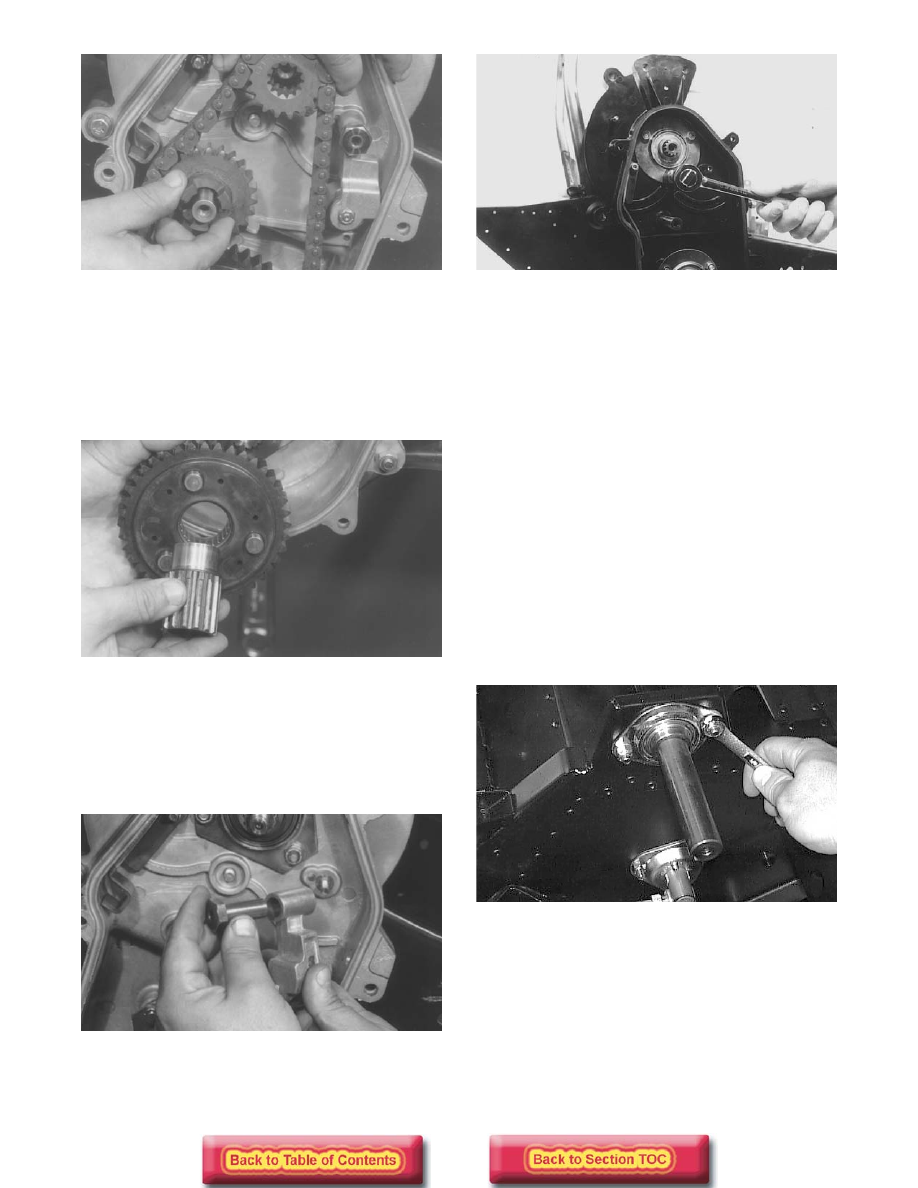
„ NOTE: If the chain is too tight and wont allow the
top sprocket to be removed, remove the PTO-side
driven shaft bearing. This will allow the driven
shaft to be lifted at the PTO-side and will loosen
the chain.

18. Remove the driveshaft extension, bottom sprocket,

and spacer washer.

AF427

19. Check the idler gear shaft. If the shaft surface is

rough, remove the shaft using a pair of vise-grip
pliers. Rotate the shaft counterclockwise.

20. Remove the shoulder nut securing the chain

tightener arm; then remove the arm from the chain
case.

AF447

21. Remove the three lock nuts securing the top

bearing flange plate. Remove the flange plate,
seal, and bearing.

AI018

22. Remove the three lock nuts securing the bottom

bearing flange plate. Remove the flange plate,
seal, and bearing.

„ NOTE: Steps 23-27 are for standard models.

23. Remove the screw securing the air-intake silencer

to the steering support; then pull the silencer
forward and place it on the carburetor/throttle
body assembly.

„ NOTE: Using a hold-down strap, secure the air-
intake silencer to the engine.

24. Loosen the set screw on the PTO-side driven shaft

collar. Drive the collar clockwise (opposite shaft
rotation) until it is free.

„ NOTE: A fine file should be used to remove any
burrs left by the collar set screw.

25. Remove the lock nuts and carriage bolts securing

the PTO-side driven shaft flange plates.

AF002D

26. Force the driven shaft toward the PTO-side

(rotating the shaft to prevent the brake disc from
binding on the shaft) until brake disc is free.
Account for the key.

27. Continue to slide the driven shaft until it is out of

the PTO-side. Account for a bearing, two flange
plates, and the PTO-side driven shaft collar.

„ NOTE: Steps 28-31 are for AWS VI models.

8-41

8

28. Remove the three bearing retainer nuts from the

PTO-side plate brace; then remove the machine
screws securing the PTO-side plate brace and
remove the brace.

FC140

29. Remove the two large-head rivets below the left-

side air-out vent on the left-side belly pan.

FC141

30. Using a rubber mallet (or suitable substitute), tap

the driven shaft from the chain case side until free.

FC142

31. Pull down on the side pan by the left-side hood

latch; then slide the driven shaft out the PTO-side
of the chassis.

FC143

32. Remove the skid frame from the tunnel (see

Section 9).

33. Remove the three PTO-side lock nuts securing the

driveshaft flange bearing assembly and cable
adapter. Remove the adapter and speedometer
cable.

AF053

34. Tap the driveshaft toward the chain case to unseat

the MAG-side bearing. Remove the bearing.

35. Slide the driveshaft toward the MAG-side until the

PTO-side of the driveshaft is out of its mounting
hole. Tilt the end of the driveshaft away from the
tunnel and slide the driveshaft free of the tunnel.
Remove the track.

AF055

8-42

36. Scribe a line on the driveshaft along the edge of

each sprocket to aid in assembly. Loosen the set
screw on the collar and drive the collar clockwise
until free; then remove the bearing and flange
plates from the driveshaft.

37. Press the sprockets off the driveshaft.

38. If applicable, remove the six socket-head cap

screws and lock nuts securing the brake disc to the
hub; then separate disc and hub.

AF446

CLEANING AND INSPECTING

„ NOTE: Whenever a part is worn excessively,
cracked, or damaged in any way, replacement is
necessary.

1. Thoroughly wash all metallic components in parts-

cleaning solvent. Dry using compressed air.

2. Wash all non-metallic components with soap and

water.

3. Inspect the driveshaft and driven shaft for

damaged splines or stripped threads.

4. Inspect the bearings for any roughness or damage.

5. Inspect the seals for any breaks or damage.

6. Inspect the track for cuts, gouges, or wear.

7. Inspect the keyways in the driven shaft and the

brake hub (if applicable) for wear or damage.

8. Inspect the brake disc for wear or cracks.

9. Inspect the track drive sprockets for wear or

damage.

10. Inspect the top sprocket for any chipped or worn

teeth.

11. Inspect the bottom sprocket teeth for wear. Turn

the inner sprocket bearing by hand and inspect for
any signs of being rough.

12. Inspect the three bottom sprocket drive pins.

Check the pin edges for chipping and wear.

13. Inspect the drive pin springs for tension by

pushing each pin into the sprocket and releasing it.
It must snap back out without any signs of
binding. If any of these items (pins, bearing,
sprocket, teeth) appear worn, replace the sprocket
as an assembly.

AI019

14. Inspect the idler gear sprocket teeth and bearings.

Rotate the inner bearings by hand. Check each
sprocket tooth for any signs of chipping and wear.

15. Closely inspect the drive chain for broken links.

16. Inspect the reverse gear. Inspect the teeth for wear

and chipping. Inspect the edges of drive pin holes
for any signs of chipping and wear.

17. Remove the snap ring from the reverse gear.

Remove the outer thrust washer, thrust bearing,
and inner thrust washer. Inspect the thrust bearing
by placing it between the two thrust washers and
rotating the thrust washer. Rotation must feel
smooth. If any roughness is noted, replace the
thrust washers and bearing as a set.

18. Inspect the chain tightener bearing. Rotate the

tightener roller and check for smooth rotation. If
rotation feels rough, replace roller and bearing
assembly.

ASSEMBLING

1. If applicable, secure the hub to the brake disc with

six socket-head cap screws (coated with red
Loctite #271) and lock nuts. Tighten lock nuts to
0.4 kg-m (36 in.-lb).

AF445

8-43

8

2. Press the sprockets on the driveshaft noting the

scribed marks on the shaft and the timing mark
found on one tooth of each sprocket. The timing
mark is the letter T molded into the outer surface
of one drive tooth. All the T markings must be in
alignment.

„ NOTE: Sprocket style will vary from model to
model.

739-057A

„ NOTE: Make sure all sprockets are installed cor-
rectly to ensure correct timing of the sprockets.
The bearing is positioned between the flange
plates.

3. Assemble the driveshaft components on the PTO-

side of the driveshaft. Install the bearing lock
collar; then install the flange bearing assembly
with the bolts facing towards the tunnel.

AF055

4. Position the front of the track up into the tunnel.

Install the driveshaft with the splined end through
its mounting hole in the chain case.

5. Place the PTO-side of the driveshaft into position

by sliding the bolts of the flange bearing assembly
through the holes in the tunnel.

6. Place the cable adapter into position on the flange

bearing assembly bolts. Secure with three lock
nuts. Tighten to 2.2-2.5 kg-m (16-18 ft-lb).

AF053

„ NOTE: Steps 7-11 are for standard models.

7. Slide the MAG-side bearing onto the driveshaft

(inner race flange must be positioned toward drive
chain); then install the O-ring and flange plate.
Secure with three carriage bolts and lock nuts.
Tighten to 2.2-2.5 kg-m (16-18 ft-lb).

„ NOTE: Prior to installation, lubricate the O-ring
with Low-Temp Snowmobile Grease (p/n 0636-
593).

8. Install the brake hub key into the driven shaft

keyway; then slide the brake disc into position on
the splined end of the driven shaft.

9. Install the PTO-side bearing with collar and flange

plates on the driven shaft; do not tighten the collar
at this time. Place the driven shaft into position
making sure the brake disc and flange plates are
properly positioned. Secure the PTO-side bearing
and flange plates with two carriage bolts and lock
nuts. Tighten to 2.2-2.5 kg-m (16-18 ft-lb).

10. On the MAG-side driven shaft, install the bearing,

O-ring, and flange plate. Secure with three lock
nuts. Tighten to 2.2-2.5 kg-m (16-18 ft-lb).

„ NOTE: Prior to installation, lubricate the O-ring
with Low-Temp Snowmobile Grease (p/n 0636-
593).

„ NOTE: If washers were removed from behind the
upper sprocket, install them at this time.

11. Install the spacer washer on the driveshaft.

! CAUTION

Tighten the flange plate nuts evenly or the O-ring
seal may be damaged.


Content   ..  108  109  110  111   ..