Snowmobile Arctic Cat (2004 year). Manual - part 103
8-12
Drive Train and
Brake Systems
This section has been organized into sub-sections for
servicing drive train and brake systems; however,
some components may vary from model to model. The
technician should use discretion and sound judgment
when removing and installing components.
NOTE: Some illustrations and photographs used
in this section are used for clarity purposes only
and are not designed to depict actual conditions.
Drive Belt
The belt dimensions and construction are two factors
that influence the performance of the drive system.
The two belt dimensions that are important to the per-
formance of the snowmobile are the outside circumfer-
ence and the width. Both of these dimensions will
influence shifting characteristics.
If the drive belt is longer than specified, the drive
clutch and driven pulley will not have the full shift
ratio. Also, a too-long drive belt will cause poor accel-
eration and a decrease in top speed.
If the drive belt is shorter than specified, the drive
clutch and driven pulley will have a different shift pat-
tern because they are in different ratios from those for
which they were originally matched. A too-short drive
belt will cause a loss in performance and a bog on
engagement.
NOTE: A drive belt that is worn thin may produce
the same effect as one that is too long.
Drive belt construction has an influence on the way the
drive clutch and driven pulley will shift and on the
amount of power that will be transmitted through the
system. ONLY ARCTIC CAT DRIVE BELTS
SHOULD BE USED. Different brands of belts may
not have the same construction causing either more
friction or more slippage when the belt is wedged
between the sheaves and, thus, a loss of efficiency.
NOTE: A stiff belt causes a HP loss to the track.
As a belt warms up, it gets more flexible and trans-
mits power with less HP loss.
Drive Clutch
CHANGING CAM ARMS (9-Post Style)
The cam arms on the drive clutch can be changed
without disassembling the clutch. To change the cam
arms, use the following procedure.
1. Check to make sure the ignition switch is in the
OFF position.
2. Remove the drive belt.
3. Compress the movable sheave approximately 2.5
cm (1 in.) and while holding it in this position,
insert a flat bar firmly between the bottom side of
the spider and the inner surface of the movable
sheave. Slowly release the movable sheave.
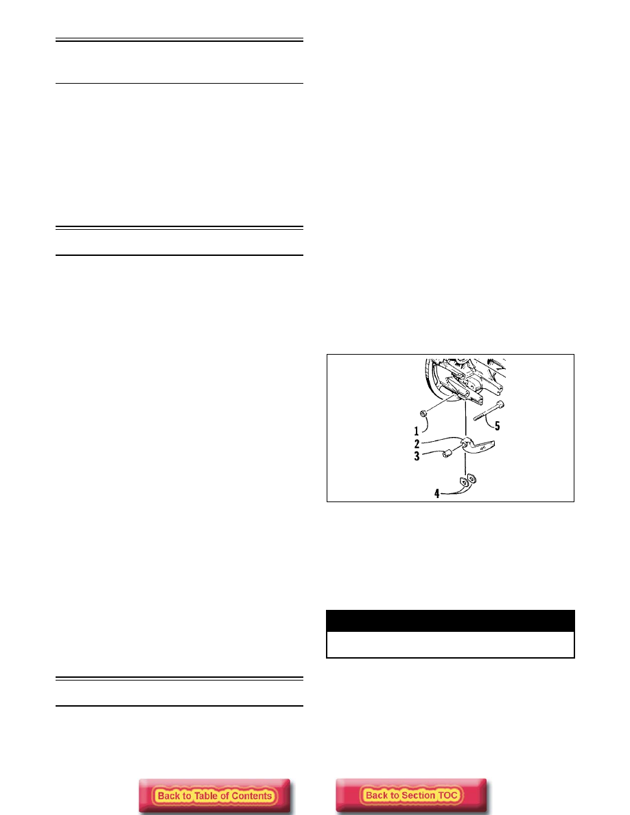
4. Remove the lock nuts from the three cam arm
pins.
5. Remove the cam arm pins one at a time; then
remove the cam arm with bushing and account for
the washers.
NOTE: When installing cam arms, always use
new lock nuts. Make sure the head of each cam
arm pin is positioned towards the direction of
drive clutch rotation. Tighten nuts until they con-
tact the shoulder of the cam arm pin; then tighten
an additional 1/8 turn.
733-452B
6. Change the cam arms and secure with new lock
nuts and existing pins making sure the head of
each pin is positioned toward the direction of drive
clutch rotation.
NOTE: The drive clutch rotates counterclock-
wise.
CHANGING CAM ARMS (6-Post Style)
The cam arms on the drive clutch can be changed
without disassembling the clutch. To change the cam
arms, use the following procedure.
! WARNING
Do not run the engine with the drive belt removed
or the bar in the clutch.
KEY
1. Lock Nut
2. Cam Arm
3. Bushing
4. Washer
5. Pin