Snowmobile Arctic Cat (2002 year). Manual - part 120


  Index      Snowmobiles / ATV     Snowmobile Arctic Cat - service manual 2002 year


Search            


Content   ..  118  119  120  121   ..


Snowmobile Arctic Cat (2002 year). Manual - part 120


8-38

7. Slide the MAG-side bearing onto the driveshaft

(inner race flange must be positioned toward drive

chain); then install the O-ring seal and flange

plate. Insert the cap screws from the inside of the

tunnel through the chain case, seal, and flange.

Secure with three lock nuts. Tighten to 2.2-

2.5 kg-m (16-18 ft-lb).

8. Place the bottom sprocket onto the splines. Finger-

tighten a lock nut (threads coated with blue Loctite

#242) and spring washer. DO NOT TIGHTEN AT

THIS TIME.

9. Install the brake hub key into the driven shaft

keyway.

10. Install the PTO-side bearing with collar and flange

plate on the driven shaft; do not tighten the collar

at this time. Place the driven shaft into position

making sure the brake disc and flange plate are

properly positioned. Secure the PTO-side bearing

and flange plate with two carriage bolts and lock

nuts. Tighten to 2.2-2.5 kg-m (16-18 ft-lb).

11. On the MAG-side of the driven shaft, apply

Scotch Bond Adhesive #4174 to the bearing

seating area adjacent to the shaft splines. Install

the bearing, seal, and flange plate. Secure with

three lock nuts. Tighten to 2.2-2.5 kg-m (16-

18 ft-lb).

„ NOTE: If washers were removed from behind the
top sprocket; install them at this time.

12. Loop the chain around the bottom sprocket and

slide the top sprocket with chain onto the driven

shaft. Secure the top sprocket with a lock nut

(threads coated with blue Loctite #242) and spring

washer. Tighten to 4.8-5.5 kg-m (35-40 ft-lb).

Tighten the bottom sprocket lock nut to 4.8-

5.5 kg-m (35-40 ft-lb).

AF344D

AF345D

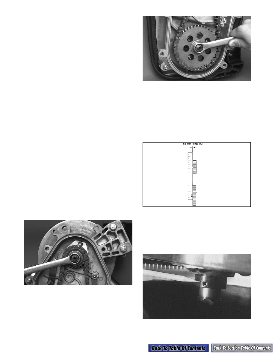
13. Check the alignment of the sprockets using the

following procedure.

A. Place a straightedge against the faces of the

sprockets.

B. Using a feeler gauge, check for clearance along

the faces of both sprockets. If clearance

exceeds 0.8 mm (0.030 in.), shimming is neces-

sary.

0725-171

„ NOTE: Sprockets can only be shimmed out.

14. On the PTO-side of the driven shaft and the track

driveshaft, slide the lock collar against the bearing,

drive the collar in the direction of rotation until

tight, and tighten the collar set screw to 0.4 kg-m

(36 in.-lb).

AF058

15. Install the skid frame (see Section 9).

8-39

8

16. Remove the hold-down strap securing the air-

intake silencer; then place the silencer into

position making sure the boot is properly

positioned on the carburetors/throttle body.

17. Secure the silencer to the steering support with the

two screws.

18. Apply a light coat of grease or Loctite Anti-Seize

Thread Compound (p/n 0678-146) to the driven

shaft; then install the driven shaft alignment

washers (as required) and key. Install the driven

pulley, stub shaft, alignment washers (as

required), washer, and cap screw. Tighten the cap

screw to 2.6-3.3 kg-m (19-24 ft-lb).

„ NOTE: Make sure keyways match when install-
ing the driven pulley. Arrange washers to allow the
least amount of float on the driven shaft. A maxi-
mum of 1.5 mm (0.060 in.) float is allowable.

AF057

19. Check the alignment of the drive clutch/driven

pulley (see Drive Clutch/Driven Pulley in this

section).

20. Tip the snowmobile onto the PTO-side using

cardboard to prevent scratching the belly pan; then

install the washers, rollers, and spring. Secure with

two washers and cotter pins.

AF113D

21. Tighten the mechanical chain tensioner finger-

tight; then lock the jam nut against the chain case.

AF347D

22. Place the front roller cage and roller into position

and secure with the flex lock nut.

23. Install the drain plug and tighten to 4.8 kg-m

(35 ft-lb); then pour 236 ml (8 fl oz) of Arctic Cat

Transmission Lube (p/n 0636-817) into the chain

case.

24. Check the position of the chain-case cover O-ring

seal; then place the chain-case cover into position

and secure with six cap screws and lock washers.

Tighten to 1.7-2.1 kg-m (12-15 ft-lb).

AF111D

25. Install the drive belt and check drive belt

deflection (see Drive Clutch/Driven Pulley in this

section). Secure the belt guard.

8-40

Chain Adjuster

REMOVING AND DISASSEMBLING

1. Remove the small plug from the adjuster housing

and install an 8-32 set screw into the threaded hole

of the adjuster housing.

AF416

2. Using a 3/4-in. wrench, remove the chain adjuster

from the chain case.

AF417

3. Remove the adjuster stem from the end of the

adjuster screw.

AF418

4. Using a small piece of wire, remove the small

spring from the end of the adjuster screw.

AF401

5. While holding the end cap in position, remove the

three cap screws securing the end cap to the

adjuster housing.

AF419

6. Slowly and carefully lift the end cap from the

adjuster housing until it is free of the hooked end

of the spring.

AF420

7. Remove the O-ring seal from the adjuster housing.

8. Carefully lift the spring from the housing and

secure the spring using a cable tie.

8-41

8

AF421

9. Remove the set screw from the adjuster housing;

then remove the adjuster socket from the housing

by pulling it free of the adjuster bolt.

AF422

10. Rotate the adjuster bolt counterclockwise until it is

free of the housing; then remove the adjuster bolt.

AF423

11. Wash all components in parts-cleaning solvent and

inspect all components for any signs of wear.

ASSEMBLING AND INSTALLING

1. Apply a light coat of oil to the threads of the

adjuster bolt; then turn the adjuster bolt clockwise

into the housing a few turns.

AF423

2. Slide the adjuster socket over the end of the

adjuster bolt and push the socket down firmly into

position. Rotate the adjuster socket clockwise until

its flange seats against the housing inner surface.

AF424

3. With the flat surface of the adjuster socket located

under the threaded hole in the housing, install an

8-32 set screw.

AF403


Content   ..  118  119  120  121   ..