Snowmobile Arctic Cat (2002 year). Manual - part 119


  Index      Snowmobiles / ATV     Snowmobile Arctic Cat - service manual 2002 year


Search            


Content   ..  117  118  119  120   ..


Snowmobile Arctic Cat (2002 year). Manual - part 119


8-34

SC013D

32. Check the alignment of the drive clutch/driven

pulley (see Drive Clutch/Driven Pulley in this

section).

33. Assure that the chain case drain plug is tightened

to 4.8 kg-m (35 ft-lb); then pour 354 ml (12 fl oz)

of Arctic Cat Transmission Lube (p/n 0636-817)

into the chain case.

34. Install the drive belt and check belt deflection.

Secure the belt guard.

35. Install and secure the battery tray and battery; then

connect the battery cables making sure to connect

the positive cable first.

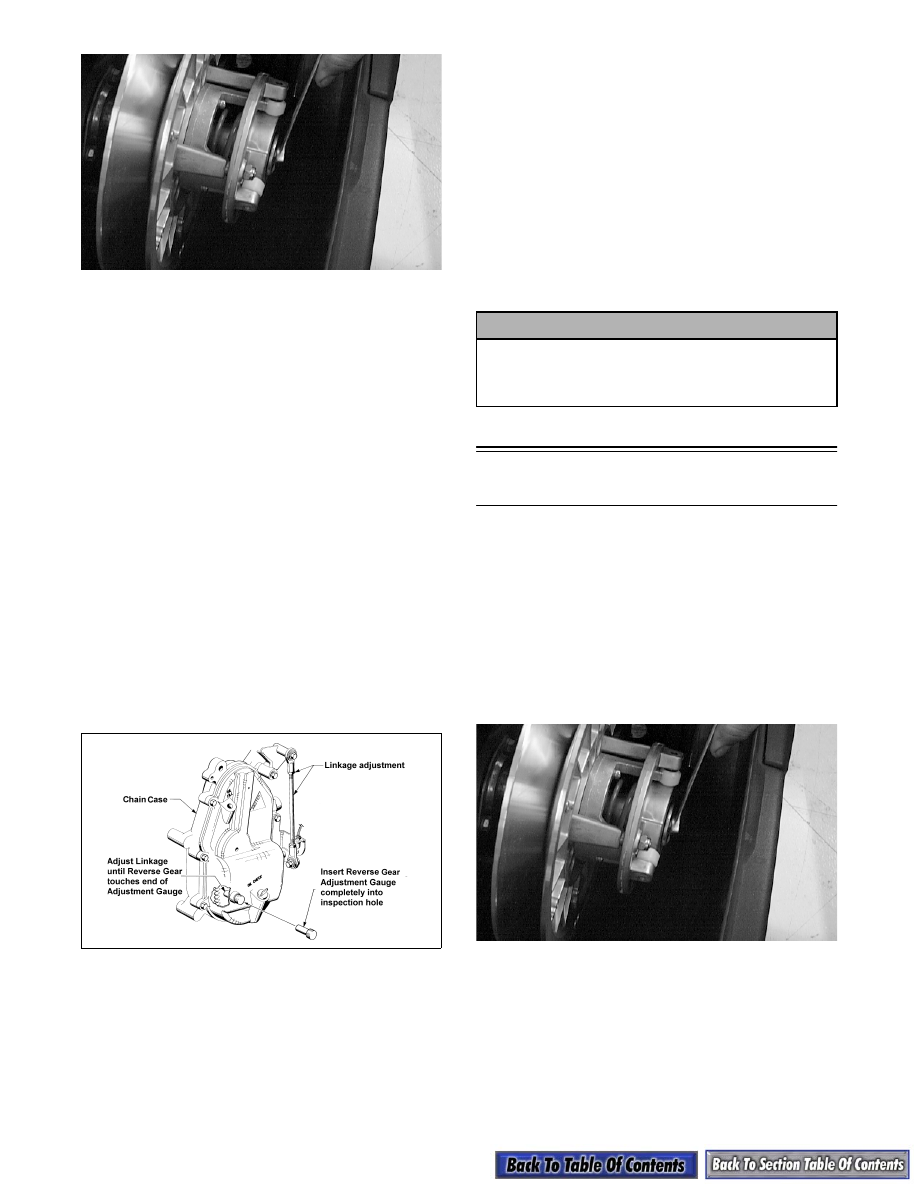
ADJUSTING REVERSE LINKAGE

1. Start the engine; then test the shifting

characteristics of the reverse transmission.

2. If adjustment of the reverse gear is necessary, stop

the engine and remove the chain case inspection

plug located behind the oil level stick; then insert

the Reverse Gear Adjustment Gauge (p/n 0644-

244) completely into the inspection hole.

0731-734

3. Pull the shift lever into the reverse position while

holding the adjustment gauge firmly against the

chain case cover. Slight outward pressure should

be felt on the gauge as the lever locks into reverse.

4. If no contact is noted, loosen the jam nuts securing

the lower shift linkage and adjust the linkage rod

until the gauge is pushed out of the chain case

0.254-0.381 mm (0.010-0.015 in.). Lock the

adjustment by tightening the jam nuts securely

against the tie rod ends.

„ NOTE: To adjust the linkage rod, the shift lever
must be moved to the forward position.

5. Install the inspection plug.

6. Start the engine; then test the shifting

characteristics of the reverse transmission. Adjust

as necessary.

Drive Train/Brake Disc 

(w/o Reverse)

DISASSEMBLING

1. Remove the chain-case drain plug (located on the

lower back side of the chain case inside the tunnel)

and drain the chain case lubricant.

2. Open the belt guard and remove the drive belt.

3. Remove the cap screw and washer securing the

driven pulley; then account for and note the

position of any alignment washers.

SC013D

4. Slide the driven pulley off the driven shaft; then

remove the driven pulley from the engine

compartment. Account for the stub shaft, key, and

alignment washers.

„ NOTE: If the driven pulley is tight on the driven
shaft, pull the driven pulley off using the Driven
Pulley Puller (p/n 0744-023).

! CAUTION

The linkage must be properly adjusted. If the
linkage is too short, damage to the shift fork may
occur. If the linkage is adjusted too long, the
gears will not shift totally into reverse.

8-35

8

AF120D

5. Remove the cap screws and lock washers securing

the chain-case cover; then remove the cover.

AF111D

6. Loosen the mechanical chain tensioner bolt; then

remove the cotter pins and washers securing the

tensioner spring to the link pins. Remove the

spring, rollers, and washers.

AF347D

7. Remove the flex nut securing the front roller cage

and roller. Remove the cage and roller.

8. Set the brake lever lock; then remove the lock nut

and spring washer securing the bottom sprocket

and the lock nut and spring washer securing the

top sprocket.

AF345D

AF344D

9. Slide both sprockets with chain off the shafts.

Account for washer(s) behind the top sprocket.

Release the brake lever lock.

„ NOTE: If a sprocket will not slide off the shaft,
thread the nut onto the shaft; then use a puller to
loosen the sprocket. The nut will prevent damage
to the threads.

10. Remove the six lock nuts securing the top and

bottom chain case flange plates. Remove the

flange plates, seals, and bearings.

AF116D

11. Remove the screws securing the air-intake silencer

to the steering support; then pull the silencer

forward and place it on the carburetors/throttle

body.

„ NOTE: Using a hold-down strap, secure the air-
intake silencer to the engine.

8-36

12. Loosen the set screw on the PTO-side driven shaft

collar. Drive the collar clockwise (opposite shaft

rotation) until it is free.

„ NOTE: A fine file should be used to remove any
burrs left by the collar set screw.

13. Remove the two lock nuts and carriage bolts

securing the PTO-side driven shaft flange plate.

14. Force the driven shaft toward the PTO-side

(rotating the shaft to prevent the brake disc from

binding on the shaft) until the brake disc is free.

Account for the key.

15. Continue to slide the driven shaft until it is out of

the PTO-side. Account for a bearing, flange plate,

and the PTO-side driven shaft collar.

16. Remove the skid frame from the tunnel (see

Section 9).

17. Remove the three PTO-side lock nuts securing the

driveshaft flange bearing assembly and the

speedometer cable adapter. Remove the cable

adapter and speedometer cable.

AF053

18. Tap the driveshaft toward the chain case to unseat

the MAG-side bearing. Remove the bearing.

19. Slide the driveshaft toward the MAG-side until the

PTO-end of the driveshaft is out of its mounting

hole. Tilt the end of the driveshaft away from the

tunnel and slide the driveshaft free of the tunnel.

Remove the track.

AF055

20. Scribe a line on the driveshaft along the edge of

each sprocket to aid in assembly. Loosen the set

screw on the collar and drive the collar clockwise

until free; then remove the bearing and flange

plates from the driveshaft.

21. Press the sprockets off the driveshaft.

22. Remove the six socket-head cap screws and lock

nuts securing the brake disc to the hub; then

separate disc and hub.

AF446

CLEANING AND INSPECTING

„ NOTE: Whenever a part is worn excessively,
cracked, or damaged in any way, replacement is
necessary.

1. Thoroughly wash all metallic components in parts-

cleaning solvent. Dry using compressed air.

2. Wash all non-metallic components with soap and

water.

3. Inspect the driveshaft and driven shaft for

damaged splines or stripped threads.

4. Inspect the bearings for any roughness or damage.

5. Inspect the seals for any breaks or damage.

6. Inspect the track for cuts, gouges, or wear.

7. Inspect the keyways in the driven shaft and the

brake hub for wear or damage.

8. Inspect the brake disc for wear or cracks.

9. Inspect the chain, sprockets, and chain tensioner

components for wear or damage.

10. Inspect the track drive sprockets for wear or

damage.

8-37

8

ASSEMBLING

1. Secure the hub to the brake disc with the six

socket-head cap screws and lock nuts. Tighten the

lock nuts to 0.4 kg-m (36 in.-lb).

AF445

2. Press the sprockets on the driveshaft noting the

scribed marks on the shaft and the timing mark

found on one tooth of each sprocket. The timing

mark is the letter T molded into the outer surface

of one drive tooth of the inside sprockets and on

the inside surface of the outside sprockets. All the

T markings must be in alignment.

„ NOTE: Sprocket style will vary from model to
model.

0728-351

0727-829

727-829A

„ NOTE: Make sure the sprockets are installed
correctly and the bearing is positioned between
the flange plates ensuring correct timing of the
sprockets.

3. Assemble the driveshaft components on the PTO-

end of the driveshaft. Install the bearing lock

collar; then install the flange bearing assembly

with the bolts facing towards the tunnel.

4. Position the front of the track into the tunnel.

Install the driveshaft with the splined end through

its mounting hole in the chain case.

AF055

5. Place the PTO-end of the driveshaft into position

by sliding the bolts of the flange bearing assembly

through the holes in the tunnel.

6. Place the cable adapter into position on the flange

bearing assembly bolts. Secure with three lock

nuts. Tighten to 2.2-2.5 kg-m (16-18 ft-lb).

AF053


Content   ..  117  118  119  120   ..