Snowmobile Arctic Cat (2002 year). Manual - part 81


  Index      Snowmobiles / ATV     Snowmobile Arctic Cat - service manual 2002 year


Search            


Content   ..  79  80  81  82   ..


Snowmobile Arctic Cat (2002 year). Manual - part 81


5-43

5

0725-653

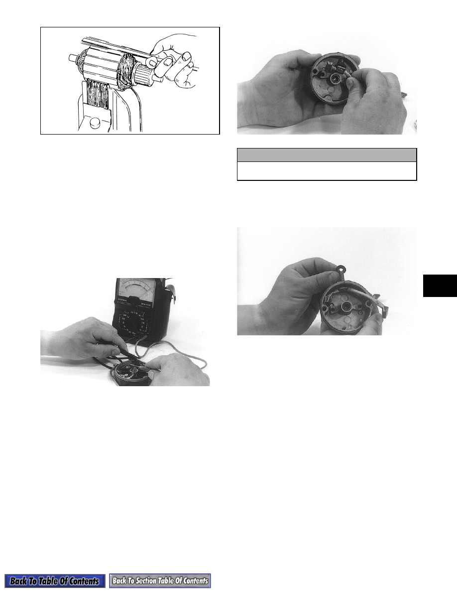
11. Inspect the ground brushes to make sure they are

properly grounded. Use the multitester and the

following procedure:
A. Set the selector on the X1K position; then touch

the leads and zero the meter.

B. Touch the black tester lead to a ground brush.

C. Touch the red tester lead to the commutator

cap. The meter needle should move to the right.

If the needle does not move to the right, check

that the ground connection is tight and clean.

Recheck for proper ground. If there still isn't

any meter needle movement, replace the

brushes as a set along with new brush springs.

AI035

ASSEMBLING

1. Install the stud with the positive brush set attached

in the commutator cap. Make sure the insulator is

in position over the stud and the longest brush lead

is positioned to the right of the stud hole.

AI038

2. In order from disassembling, place the washers on

the stud. Apply a small amount of red Loctite #271

to the stud threads and secure with the nut. Tighten

to 0.7 kg-m (5 ft-lb).

AI039

3. Place the brush holder into position in the

commutator cap.

„

NOTE: Position the longest positive brush lead

beneath the ground wire on right side.

4. Place a cap screw through the left ground brush

lead eyelet and position the eyelet flat against the

brush holder. Secure with a cap screw.

5. Place the right ground brush eyelet flat against the

brush holder and secure with a cap screw. The

eyelet stem must be positioned to the top of the

threaded hole boss in the commutator cap.

! CAUTION

Check the stud to make sure insulator is
between stud and cap on backside.

5-44

AI040

6. Place the four brush springs into the brush holder

and place each brush (flat side down) on top of the

springs.

„

NOTE: Apply a small amount of low-temperature

grease to the cap bushings.

7. Place a wave washer and a thrust washer on the

armature shaft; then slide the front cap into

position.

8. Apply a thin coat of grease to the armature shaft

and slide the drive gear and spring washer onto the

shaft. Secure with a snap ring.

9. Start the commutator end of the armature

assembly into the starter case at the end with the

fields nearest the end of the housing. Align the

marks on the front cap and case.

AI042

10. Compress the four brushes (flat side down) into

the brush holder. Hold the brushes in position

using the Starter Assembly Tool (p/n 0644-052).

AI043

11. Carefully place the starter case and armature

assembly into the commutator cap. Again, check

to make sure the scribed marks of these two

components are aligned. With the case flat on the

assembly tool, slowly pull the tool from the starter

motor. The case should then drop into place.

AI044

12. Apply red Loctite #271 to the threads of the two

through-bolts; then install and secure the bolts.

Tighten to 1-1.4 kg-m (7-10 ft-lb).

„

NOTE: The starter shouldn’t be picked up until

the two through-bolts have been secured. Spring
pressure from the brush springs will push the
commutator cap off the case.

DISASSEMBLING PINION

1. Remove the pinion assembly. Account for any

washers and spacers.

2. Remove the stopper, spring, and pinion gear from

the shaft.

CLEANING AND INSPECTING 

PINION

„

NOTE: Whenever a part is worn excessively,

cracked, or damaged in any way, replacement is
necessary.

1. Using parts-cleaning solvent, wash grease from

the pinion gear. Dry with compressed air.

2. Inspect the pinion gear for wear. If the gear is

worn or chipped, replace the pinion assembly.

5-45

5

3. Inspect the inner gear and housing. If the gear

shows any signs of wear, replace the pinion

assembly.

4. Inspect the inner housing for tightness and cracks.

If the housing shows any signs of being loose or

cracked, replace the pinion assembly.

5. Inspect the pinion return spring for wear. If the

spring shows any worn areas, replace the spring.

ASSEMBLING/INSTALLING PINION

1. Apply a thin coat of grease to the gear; then slide

the pinion onto the driveshaft along with the return

spring and stopper.

2. Slide the spacers and washers onto the shaft and

install the assembled pinion gear assembly. Slide

the remaining thrust washer onto the bracket side

of the shaft.

3. Install the pinion assembly.

TESTING STARTER MOTOR

„

NOTE: Before installing the starter motor, per-

form test to ensure proper operation using the fol-
lowing procedure.

1. Attach a black jumper cable to a good ground on

the starter.

2. Attach the opposite end of the black jumper cable

to the negative post of a good 12V battery.

3. Attach the red jumper cable to the positive post of

the battery.

4. Holding the starter firmly down on a work bench,

touch the red jumper cable to the positive cable

stud of the starter.

„

NOTE: Starter motor must instantly spin at a

high RPM. The pinion must snap out against the
stopper. If the motor does not spin, remove the red
cable immediately. Check the battery condition
and all connections. If everything checks out satis-
factorily and the starter does not spin, disassem-
ble the motor and check for pinched or broken
wires.

INSTALLING

1. Place the starter motor into the bracket; then

secure with existing hardware. Tighten to 1.7-2.1

kg-m (12-15 ft-lb).

2. Attach the red positive cable to the positive stud

terminal and secure with a nut and washers. While

tightening the nut, hold the cable in position so it

is parallel with the starter.

3. Secure the positive cable to the starter motor with

a long cable tie.

4. Connect the cable to the positive post of the

battery; then connect the negative cable to the

negative post.

5. Install the drive clutch.
6. Install the expansion chamber(s).

! WARNING

Be sure to keep clear of the pinion gear area as it
will spin at a high RPM when the red cable is
touched to the positive stud. Personal injury may
result if contact is made with a spinning pinion.

! CAUTION

Check the cable installation to make sure it isn’t
near any moving parts or against any sharp
edges.

5-46

Troubleshooting 

Electric Start

Problem: Hot or Smoking Wires

Condition

Remedy

1.

System wired incorrectly

1. Check wiring against wiring diagram

Problem: Starter Does Not Turn Over

Condition

Remedy

1.

Battery discharged

2.

Connection loose

3.

Grounding improper

4.

Fuse blown — not installed

1. Check/charge the battery

2. Check tightness of all connections

3. Check ground connections

4. Check — replace fuse


Content   ..  79  80  81  82   ..