Snowmobile Arctic Cat (2002 year). Manual - part 79
5-35
5
AO102D
2. Set the selector in the X10 position.
3. Connect the red tester lead to the green/white wire;
then connect the black tester lead to the brown
wire.
4. Ignition timing sensor resistance must be between
148-222 ohms (570 cc) or 152-228 ohms (1000
cc).
LIGHTING COIL
1. Disconnect the main wiring harness from the
engine.
2. Set the selector in the X1 position.
3. Connect the two meter leads to each of the yellow
leads in the connector from the engine.
AK015
4. Lighting coil resistance must be between 0.12-
0.18 ohm.
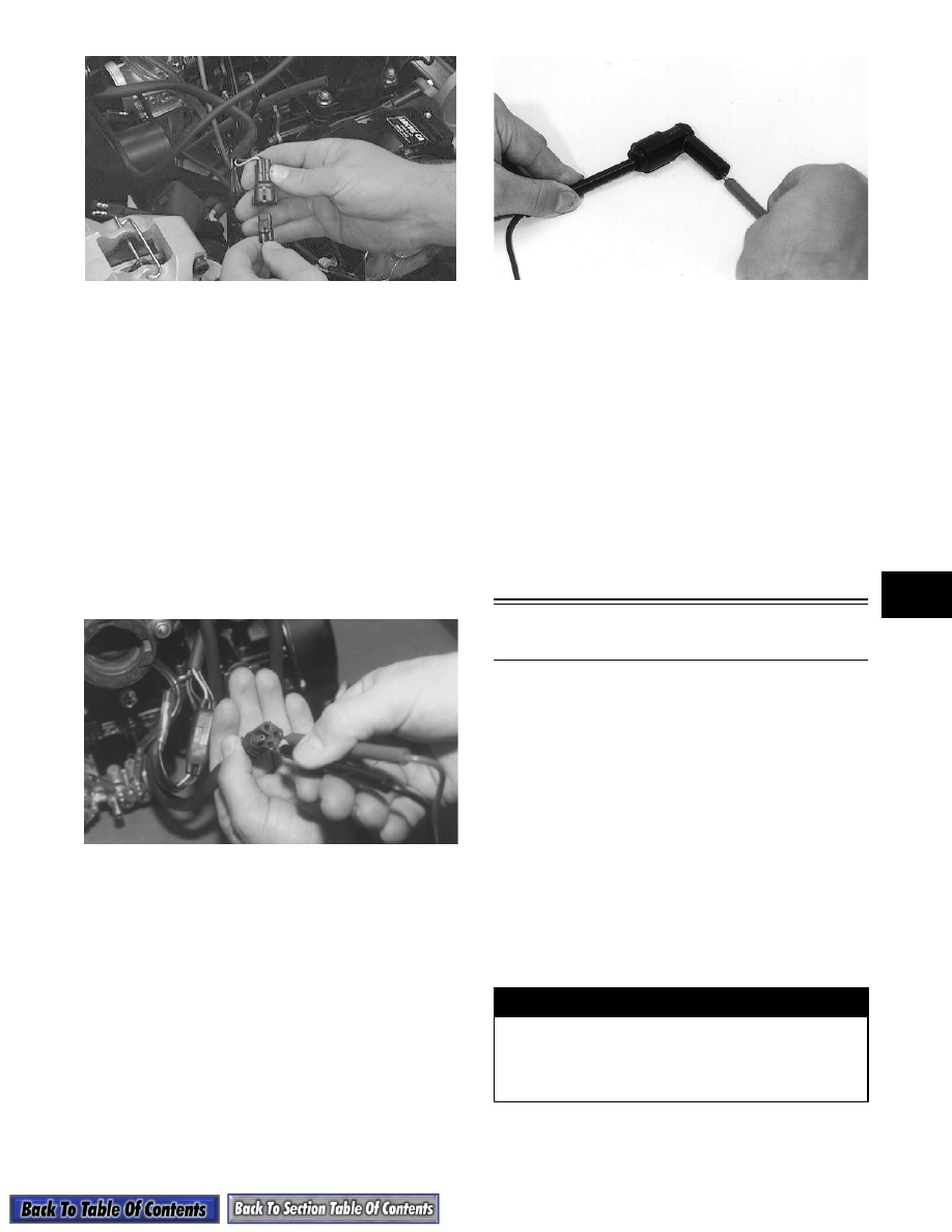
SPARK-PLUG CAP
1. Remove the spark-plug caps from the high tension
wires.
2. Set the selector in the X1K position.
3. In turn on each cap, touch a tester lead to each end
of the spark-plug cap.
B170
4. Spark-plug cap resistance must be between 4000-
6000 ohms.
IGNITION SWITCH
1. Remove the main wiring harness connectors from
the ignition switch.
2. Rotate the key to the OFF position.
3. The meter must read less than 1 ohm resistance
between the ignition switch terminals.
4. Rotate the key to the RUN position.
5. The meter must read OL (infinite resistance).
Peak Voltage Tests
(Fan Cooled Models)
NOTE: The following tests should be made using
the Fluke Model 73 Multimeter (p/n 0644-191) with
Peak Voltage Reading Adapter (p/n 0644-307).
NOTE: Peak voltage test specifications are on
the Electrical Specifications (Individual) pages in
this section.
The Fluke Multimeter w/Adapter can perform the fol-
lowing tests.
A. Stator/Charge Coil(s) Output
B. Lighting Coil Output
C. Primary/Secondary Coil Output
D. Voltage Regulator Output
!WARNING
Most voltages generated by the ignition system
are sufficient to interrupt pacemakers! All techni-
cians, especially those using pacemakers, must
avoid contact with all electrical connections
when making these tests.