Snowmobile Arctic Cat (2002 year). Manual - part 64


  Index      Snowmobiles / ATV     Snowmobile Arctic Cat - service manual 2002 year


Search            


Content   ..  62  63  64  65   ..


Snowmobile Arctic Cat (2002 year). Manual - part 64


4-49

4

AO145D

4. Remove the fuel injectors from the throttle body

assembly.

AO146D

Installing

1. Apply a light coat of oil to all O-rings; then install

the upper and lower O-rings onto each injector.

2. Install the injectors into the throttle body

assembly.

3. Place the injector hold-down plate into position on

top of the injectors and secure with two screws.

4. Connect the fuel delivery hose to the fuel rail and

secure with a clamp.

„

NOTE: When securing the fuel delivery hose,

position the clamp as shown.

0729-325

5. Connect the wiring harness to the injectors making

sure the number 1 harness is connected to the

MAG-side injector.

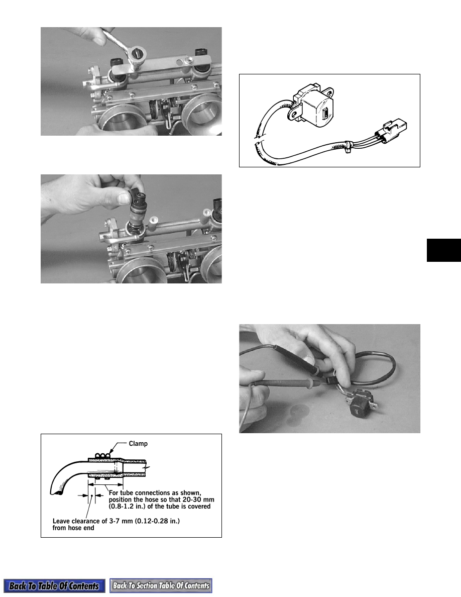
IGNITION TIMING SENSOR

0729-627

„

NOTE: This sensor is located on the top of the

magneto case on some models. On other models
the sensor is located inside the magneto case next
to the flywheel, and on these models, the recoil
starter and the flywheel must be removed to
access the sensor.

Testing Resistance

1. Disconnect the two leads from the sensor to the

main wiring harness.

2. Set the meter selector to the OHMS scale.

3. Test between the green/white and brown leads

from the sensor. Test specification is 152-228

ohms.

AO147D

Removing

1. Open the rubber boot that protects the main wiring

harness connections; then disconnect the ignition

timing sensor from the ECU wiring harness.

2. Remove the two screws securing the sensor to the

magneto housing.

3. Remove the sensor.

4-50

Installing

1. Using two screws coated with blue Loctite #242,

secure the sensor to the magneto housing (inner

mounting hole).

2. Connect the sensor to the ECU wiring harness;

then close the rubber boot.

3. Secure loose wires with cable ties.

ELECTRIC FUEL PUMP

1. Remove the hardware securing the console to the

gas tank and frame; then move the console out of

the way.

2. Disconnect the fuel pump (white two-wire

connector) from the main wiring harness.

3. Connect the positive lead of a 12-volt power

supply to  the red wire and the negative lead of the

12-volt power supply to the black wire.

4. The pump should operate (it would be heard

running).

„

NOTE: If the fuel pump fails to operate, the pump

is defective and must be replaced.

FUEL PRESSURE REGULATOR (600 cc)

Removing

1. Loosen the clamp securing the fuel return hose to

the fuel regulator; then remove the hose.

2. Remove the two screws securing the fuel pressure

regulator to the fuel rail; then slowly remove the

regulator. Account for the O-ring.

AO149D

Testing Fuel Pressure Regulator

1. Using the Fuel Pressure Tester (p/n 0644-203),

connect the tester to the regulator fuel inlet.

AO053

„

NOTE: A short piece of 3/8 in. I.D. hose will be

needed to make the above connections.

2. Pressurize the regulator to 2.0-2.2 kg/cm² (28-31.3

psi). Turn the pressure tester shut off valve to the

OFF position. Observe the gauge for several

minutes and note if there is any loss of pressure. If

pressure begins to drop, the cause may be a

ruptured diaphragm, worn spring, or leaking

valve. If the regulator fails to build or maintain

pressure, replace the regulator.

„

NOTE: If there is a drop in pressure, check the

hose connections to ensure there are no leaks.

Installing

1. Position the O-ring on the fuel pressure regulator;

then place the regulator into position on the fuel

rail. Secure with two screws.

2. Connect the fuel return hose to the regulator; then

secure with a clamp.

0729-325

! CAUTION

Since the regulator may be under pressure,
remove it slowly to release the pressure. Place
an absorbent towel around the connection to
absorb fuel.

4-51

4

WATER TEMPERATURE SENSOR

Testing Resistance

„

NOTE: The water temperature sensor is very

sensitive to temperature change. Before the resis-
tance test is conducted, it is important to know the
coolant temperature. If the engine has been oper-
ated recently and the coolant is warm, the resis-
tance will measure lower than if the coolant was at
room temperature or colder. For accurate test
results, check the coolant temperature in the filler
neck using a thermometer.

1. Disconnect the water temperature sensor wiring

harness from the main harness.

2. Set the meter selector to the OHMS position and

test the resistance between the two leads from the

sensor.

3. Compare the resistance reading to the EFI

Component Voltage/Resistance Chart - Water

Temperature in this sub-section. If resistance is

not within the specification, replace the sensor.

„

NOTE: A water temperature sensor voltage test

can be made using the EFI Analyzer. Please refer
to the analyzer test procedures provided on the
following pages.

Removing

1. Drain the cooling system.

2. Remove the throttle body assembly.

3. Disconnect the wiring harness from the water

temperature sensor.

4. Remove the sensor from the water temperature

case.

Installing

1. Apply teflon tape to the threads of the water

temperature sensor; then install the sensor.

2. Connect the wiring harness to the sensor.

3. Install the throttle body assembly.

4. Fill the cooling system.

INTAKE AIR TEMPERATURE SENSOR

Testing Resistance

„

NOTE: It is very important to know the compo-

nent temperature before conducting this test.
Allow the engine to reach room temperature.

1. Disconnect the wiring harness from the intake air

temperature sensor.

AO135D

2. Set the meter selector in the OHMS position and

test the two leads located in the sensor connector.

Compare with the EFI Component Voltage/

Resistance Chart - Air Temperature in this sub-

section.

„

NOTE: The intake air temperature sensor

employs a thermistor, which is very sensitive to
temperature changes. Resistance will change as
temperature varies.

Removing

1. Disconnect the wiring harness from the intake air

temperature sensor.

2. Using a standard screwdriver, pry the sensor end

to end to remove it from the air-intake silencer.

Account for two push pins.

Installing

1. Place the sensor into position in the air-intake

silencer and secure with push pins.

2. Connect the wiring harness to the intake air

temperature sensor. Secure the sensor leads with

cable ties so they do not rub on any other

components.

EFI Analyzer

„

NOTE: Troubleshooting EFI engines with the

APV system should be done with the Arctic Cat
EFI Analyzer (p/n 0644-342). To update your exist-
ing EFI Analyzer, order Kit (p/n 0644-341).

GENERAL INFORMATION

The EFI Analyzer (p/n 0644-302) makes it possible for

technicians to easily perform EFI system troubleshoot-

ing in a short period of time.

Before an EFI analyzer purchased prior to February 1,

1998, can be used on the batteryless EFI system, it

must be updated with the Harness and EPROM Update

Kit (p/n 0644-301) available from your Arctic Cat

Parts Department. All analyzers purchased after June

1, 1998, were updated at Arctic Cat.

4-52

To use the analyzer on the batteryless EFI system, a

12-volt battery to power the analyzer is necessary. Fol-

low the instructions under Analyzer Setup for testing

the batteryless EFI system.

Analyzer Nomenclature

730-222A

1. LCD - Liquid Crystal Display.

2. Power-Light illuminates when the analyzer is

properly connected to the snowmobile EFI

analysis test plug.

3. On/Off Switches.

4. Menu Select (up/down) - Enables selection of a

test function quickly.

5. Test - Once the test function is selected, push the

button to complete the test. The button also

cancels the current test so the next test function

can be selected.

Analyzer Test Function 

(Batteryless System)

If the EFI analyzer has been updated with the 1998

Harness and EPROM chip, it can be used to trouble-

shoot the 1997-2002 batteryless EFI system (without

the APV system). There is, however, special informa-

tion which can be retrieved from the 2000-2002 ECU

such as total running time on engine, running times by

temperature, maximum RPM by temperature, EPROM

chip change check, number of fuel changes by wire

disconnect, and last fuel type used. This information

can only be retrieved with an EFI analyzer which has

been updated with either the 1999 Harness and

EPROM Chip Update Kit (p/n 0644-301) or the 1999

EFI Analyzer EPROM chip (p/n 0643-068).

If the EFI analyzer has been updated with the new

EPROM chip (p/n 0643-068) when the MENU

SELECT buttons are pressed, there will be three

modes to select from. First mode, ARCTCO, is used to

troubleshoot the battery style EFI systems used in

1998 and prior year models. The second mode,

KOKUSAN, is used to troubleshoot the 1997-2002

batteryless EFI system. The third mode, KOKUSAN

SPECIAL, is used only to retrieve special information

(explained earlier) found only on the 2001-2002 bat-

teryless EFI system ECU.

At this point, select one of the modes by pushing the

TEST button, or the analyzer will not continue past

this point. If testing a batteryless EFI system, select

KOKUSAN on the display by pushing the TEST but-

ton. The entire system can now be tested by moving to

the next test using the MENU SELECT buttons.

If the analyzer is turned off during the test procedure,

the test function on the display will automatically start

over at the top of the list when turned back on. This

means the selection of the system being tested must be

repeated before continuing.

Once a test has been completed, press the TEST button

again to cancel the test, which allows the selection of a

different test using one of the MENU SELECT but-

tons.

„

NOTE: If the new updated EPROM chip has not

been installed, the EFI (Battery System) can be
tested; however, without the new Test Harness
and EPROM Update Kit (p/n 0644-301), the new
Arctic Cat Batteryless EFI System cannot be
tested. All EFI analyzers purchased after February
1, 1998, were updated at Arctic Cat.

Menu List Organization

(Kokusan Mode)

1. Engine RPM

2. Diagnosis memory clear

3. Memory problem diagnosis test

4. Existing problem diagnosis test

5. Barometric pressure

6. Water temperature

7. Intake air temperature

8. Throttle valve angle in degrees

9. Ignition timing

Kokusan Special Mode

The 2000-2002 batteryless EFI system has an updated

ECU. With the 2000-2002 ECU, the snowmobile can

be run with either regular gasoline or oxygenated gas-

oline. Special instructions located on top of the tool

box lid will instruct to disconnect two wires located in

front of the ECU if oxygenated gasoline is used. If reg-

ular gasoline is to be used, the two wires in front of the

ECU must remain connected or the mixture will be too

rich.


Content   ..  62  63  64  65   ..