Snowmobile Arctic Cat (2002 year). Manual - part 63


  Index      Snowmobiles / ATV     Snowmobile Arctic Cat - service manual 2002 year


Search            


Content   ..  61  62  63  64   ..


Snowmobile Arctic Cat (2002 year). Manual - part 63


4-45

4

AO138DA

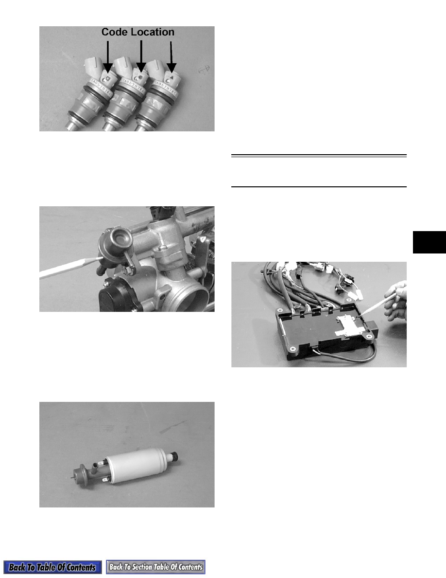
FUEL PRESSURE REGULATOR

The fuel pressure regulator is attached to the end of the

fuel rail (600 cc) and in the fuel pump (800 cc). The

fuel pressure regulator maintains the fuel pressure at a

constant level of 37.9 ± 2.2 psi (600 cc) or 48 ± 2.2 psi

(800 cc).

AO141D

On the 600 cc when fuel pressure exceeds the specifi-

cation, the spring-loaded diaphragm in the regulator

opens allowing fuel to flow through the return hose

back to the gas tank.

FUEL PUMP CIRCUIT

The fuel pump and its circuit are provided with current

from the fuel pump coil on the stator.

AO142D

For this circuit to function correctly, five components

must be in good working order.

Check the following components before considering

the fuel pump assembly to be defective.

A. Fuel pump coil - see coil test procedure.

B. Emergency stop switch and ignition switch

must be ON and in good working order.

C. Fuel pump - see fuel pump test procedure.

D. Wiring harness and connectors - clean the

connectors and test the harness.

E. ECU.

Self-Diagnostic

EFI System

INTRODUCTION

The Electronic Control Unit (ECU) contains a built-in,

self-diagnostic system which detects trouble within the

five-sensor signal network and then flashes a code on

the LED signal light, located under the left end of the

ECU.

AO153D

The fuel system and the ignition system remain two

separate systems. In a no-start situation, first deter-

mine if the problem is caused by lack of spark or by a

fuel delivery problem.

Using the EFI Ignition Analyzer, equipped with the

update EPROM (chip) and test harness, connect the

test harness to the ECU diagnostic connectors. Con-

nect the test harness red external lead to the positive

terminal of a 12-volt battery and connect the black

external test harness lead to the negative terminal.

If any of the circuits are faulty, a trouble code will now

be flashed by the LED.

If no code is flashed, turn on the analyzer. Press the

MENU SELECT buttons until the words KOKUSAN

appear on the display; then press the TEST button. The

analyzer is now programmed for testing the Arctic Cat

Batteryless EFI System.

4-46

Using the MENU SELECT buttons, press the button

repeatedly until Memory Problem Diagnosis Test

appears on the display; then press the TEST button. If

any sensors have intermittent problems, they will be

indicated on the display.

Proceed to individual components test procedures cov-

ered throughout this section.

The code flashed from the LED will first be a number

of flashes. Count the number of flashes and refer to

Trouble Codes in this sub-section. The code repeats

itself with approximately a 2-second delay between

each series of flashes.

„

NOTE: When reading the LED flash sequence,

have paper and pencil available to write down the
codes being flashed. More than one code may be
flashed.

Once the problem area has been determined, check the

components involved using the Fluke Model 73 Multi-

meter (p/n 0644-191) or the EFI Analyzer (p/n 0644-

302) depending on which test is being made.

„

NOTE: If the EFI analyzer has been updated with

the new EPROM chip, select the proper EFI system
being tested (ARCTCO for Battery System and
KOKUSAN for Batteryless System). Press the
TEST button on the analyzer and the analyzer will
remain on the system selected until it is turned off.
If the analyzer is turned off during the test proce-
dure, reselect the proper system being tested
before proceeding.

Trouble Codes

TROUBLESHOOTING INDIVIDUAL 

COMPONENTS

„

NOTE: With the Arctic Cat Batteryless EFI Sys-

tem ,  i t  is  e x tr em el y  i mpo rta nt  tha t  the   E CU
receives the proper current output from four coils
(two charge coils, an injector coil, and a fuel pump
coil) to function as designed. If a problem exists,
these coils should be checked using the following
procedures.

Charge Coil (1)/Charge Coil (2) 

Resistance Test

The charge coils power the CDI system and the ECU.

To test these coils, disconnect the 3-wire connector

from the ECU to the stator.

1. Set the meter selector to the OHMS scale and test

between the black/red and green/red wires.

2. The meter must show 17 ohms ± 20%. 

3. Test between the green/red and brown/white

wires. 

4. The meter must show 17 ohms ± 20%.

„

NOTE: If either test is not within specifications,

the stator must be replaced. Refer to the wiring
diagram in this sub-section.

Injector Coil Resistance Test

The injector coil located on the stator powers the two

injectors.

1. Disconnect the double-wire plug with two blue/

white leads from the stator to the ECU.

2. Set the meter selector to the OHMS scale.

3. Connect a meter lead to each of the blue/white

leads. The meter must show 19 ohms ± 20%.

„

NOTE: If reading is not within the specification,

recheck to confirm test results. If still out of toler-
ance, replace the stator.

„

NOTE: If the resistance test is good, a peak read-

ing voltage test should also be made. Refer to
Peak Voltage Tests and Specifications in this sub-
section.

Fuel Pump Coil Resistance Test

The fuel pump coil powers the fuel pump through the

ECU.

„

NOTE: With the engine running, there should

12.3-12.9 DC volts supplied to the fuel pump for
operation. To test fuel pump coil resistance, use
the following procedure.

1. Disconnect the double-plug with the two orange

wires from the ECU.

2. Set the meter selector to the OHMS scale. Connect

a meter lead to each of the two orange leads.

3. The meter must show 1.9 ohms ± 20%.

„

NOTE: If reading is out of tolerance, recheck to

confirm reading. If still out of tolerance, replace
the stator.

Number of 

Flashes

Trouble

1

Open or short circuit in throttle position 

sensor.

2

Open or short circuit in water 

temperature sensor.

3

Open or short circuit in intake air 

temperature sensor.

4

Open or short circuit in barometric 

pressure sensor.

5

Failure in injector(s).

4-47

4

„

NOTE: If the resistance test is good, a peak read-

ing voltage test should also be made. Refer to
Peak Voltage Tests and Specifications in this sub-
section.

Lighting Coil Resistance Test

The lighting coil located on the stator provides AC

power to the lighting system and accessories through a

charging system. To test the lighting coil resistance,

follow this procedure.

1. Disconnect the 3-wire connector at the engine.

2. Set the meter selector to the OHMS scale.

3. Test between the two yellow leads.

4. The meter must show 0.10 ohm ± 20%.

„

NOTE: If reading is out of tolerance, recheck to

confirm reading. If still out of tolerance, replace
the stator.

ECU

ACTIVATING ECU MEMORY

„

NOTE: The ECU memory on the 1997- 2002 Arc-

tic Cat Batteryless EFI system (without the APV
system) can be activated only by using the EFI
Analyzer (p/n 0644-212) which has had the updated
EFI Analyzer Test Harness and EPROM Update Kit
(p/n 0644-256) installed.

„

NOTE: Testing EFI engines with the APV system

should be done with the Arctic Cat EFI Analyzer (p/
n 0644-342). To update your existing EFI Analyzer,
order Kit (p/n 0644-341).

The ECU has a self-diagnostic mode built into the unit.

It is a very valuable tool in troubleshooting. Once the

problem area code has been flashed by the light emit-

ting diode (LED) located at the end of the ECU, follow

the troubleshooting procedure in this sub-section.

The ECU also has a memory mode for determining if

any of the five sensors have intermittently failed. To

activate the memory system, follow these steps.

1. Connect the analyzer test harness to the ECU

diagnostic connector.

2. Connect the analyzer test harness red and black

leads to a 12-volt battery.

3. Turn the analyzer switch ON.

4. Press the analyzer MENU SELECT buttons

repeatedly until KOKUSAN appears on the

display. Once the word KOKUSAN appears on

the display, press the TEST button. The analyzer is

now set up to test the batteryless EFI system.

5. Press the analyzer MENU SELECT buttons

repeatedly until the words Memory Problem

Diagnosis Test appears on the display.

6. Press the analyzer TEST button. If all sensors are

good, SENSORS ALL O.K. will appear on the

display. If any of the sensors have intermittently

failed or are faulty, they will appear on the display.

Proceed then to checking the faulty sensor

individually as covered in this section.

„

NOTE: Once problem areas have been deter-

mined, always check the component(s) for clean
and tight connections.

7. To erase the memory of the ECU, press the TEST

button once again; then push the MENU SELECT

buttons until Diagnosis Memory Clear appears on

the display. Turn the analyzer OFF and then back

ON again. Reselect KOKUSAN mode; then

proceed to the Memory Problem Diagnosis Test

and push the TEST button. The display should

indicate SENSORS ALL O.K. which indicates the

memory has been cleared.

REMOVING

„

NOTE: There isn’t a test for the ECU. If a problem

is suspected in this unit, try another ECU. When
using another ECU, it must be a 1997, 1998, 1999,
2000, 2001, and/or 2002 model with a batteryless
system. The ECU may be sent to the Arctic Cat
Service Department for testing. Please contact the
Service Department before sending any units.

1. Disconnect the two wiring harness leads from the

front of the ECU.

2. Remove the four screws securing the ECU to the

air-intake silencer.

3. Remove the ECU.

„

NOTE: If there are any questions concerning

lead or harness connections, there is an battery-
less EFI system wiring diagram in the back of this
section.

INSTALLING

1. Secure the ECU to the air-intake silencer with the

screws.

„

NOTE: Make sure the diagnostic connector plug

faces the oil reservoir.

2. Connect the wiring harness leads to the ECU.

„

NOTE: Make sure all connectors are clean and

tight. Apply dielectric grease to all connectors.

Memory Problem Diagnosis Test

4-48

Testing Individual 

Components

„

NOTE: For the following tests, use the Fluke

Model 73 Multimeter (p/n 0644-191) or a multimeter
of the same quality.

THROTTLE POSITION SENSOR 

(All Models)    

1. Disconnect the TPS wiring harness connector.

  2. Using TPS Adjustment Tool (p/n 0644-299), con-

nect its wiring harness to the TPS. Connect the

two Fluke meter leads (red and black) using the

two pin jack adapters provided with the adjust-

ment tool to the red and black jacks of the TPS

adjustment tool.

„

 NOTE: Before using the TPS adjustment tool,

verify its battery condition. The battery used in the
tool is a 9-volt battery. To check battery condition,
use a digital volt/ohmmeter set on DC volt scale.
Test between the adjustment tool black and red
jacks. Insert the red lead of the digital voltmeter
into the red jack of the adjustment tool and the
black lead of the digital voltmeter into the black
jack of the adjustment tool. If voltage is found
below 4.9 volts, replace the battery.

3. Set the multimeter selector to the DC scale; then

SLOWLY depress the throttle lever. The meter

reading should show a smooth rise all the way to

wide-open throttle. Repeat this step until it is

assured that there are no open areas or “peaks” in

the reading.

„

 NOTE: If a reading contains open areas or

peaks, the throttle position sensor may be faulty.
Refer to the proper Checking/Adjusting TPS proce-
dure in Section 5 - Digital 3-D Ignition in this man-
ual.

  4. Disconnect the adjustment tool harness from the

TPS. Connect the snowmobile TPS harness to the

TPS.

„

 NOTE: Before installing the TPS harness con-

nector, apply dielectric grease to the connector
pins.    

FUEL INJECTORS

AO139D

Testing Resistance/Voltage

1. Disconnect the fuel injector wiring harness.

2. Set the meter selector to the OHMS scale.

3. Test between the two injector terminals. Test

specification is 2.4-3.3 ohms.

AO144D

4. If not within specifications, replace the injector.

Removing

1. Loosen the clamp securing the fuel supply hose to

the fuel rail; then remove the hose from the fuel

rail.

2. Disconnect the wiring harness from each injector.

3. Remove the two screws securing the injector hold-

down plate to the throttle body assembly; then

remove the plate from the injectors.

! CAUTION

The fuel supply hose may be under pressure.
Place an absorbent towel around the connection
to absorb fuel; then remove the hose slowly to
release the pressure.


Content   ..  61  62  63  64   ..