Snowmobile Arctic Cat (2002 year). Manual - part 22


  Index      Snowmobiles / ATV     Snowmobile Arctic Cat - service manual 2002 year


Search            


Content   ..  20  21  22  23   ..


Snowmobile Arctic Cat (2002 year). Manual - part 22


2-71

2

GF316D

A001

25. Secure the air cleaner housing to the carburetor

and engine with the cap screw and flanged nuts.

GF314D

A002

26. Secure the air cleaner end cap to the air cleaner

housing with the wing nut.

Assembling Engine

(370/440 cc Models)

„

NOTE: The use of new gaskets and seals is rec-

ommended when assembling the engine.

„

NOTE: When the use of a lubricant is indicated,

use Arctic Cat 50:1 Injection Oil.

1. Install the C-ring and the five bearing retaining

pins into the lower crankcase half.

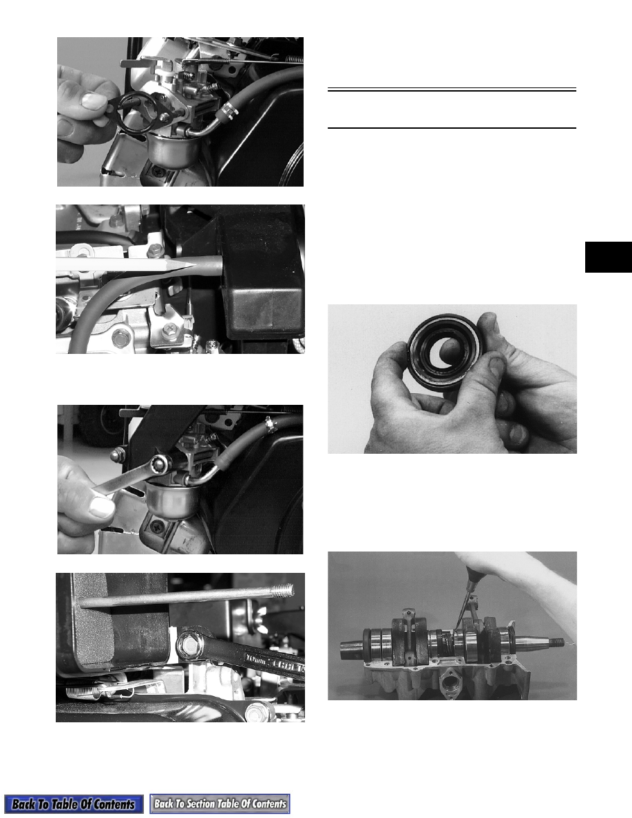
2. Lubricate the inner lips of the crankshaft oil seals

with grease; then slide the seals onto the

crankshaft making sure the spring side of each seal

faces the center of the crankshaft.

AC087

3. Apply oil to the crankshaft bearings; then install

the dowel pins, C-ring, and crankshaft into the

lower crankcase half. Be sure the alignment hole

in each bearing is positioned over its respective

bearing retaining pin in the crankcase; then seat

the crankshaft.

AB091

„

NOTE: Make sure the crankshaft center seal is

properly positioned in the groove of the lower
crankcase half.

2-72

„

NOTE: To check the bearing for proper position,

place the point of a sharp tool into the dimple
found in the bearing race. Strike the tool with the
palm of the hand in either direction. If the bearing
moves, it isn't positioned correctly and must be
rotated until it drops onto the dowel pin.

4. Apply a thin coat of Three Bond Sealant (p/n

0636-070) to the crankcase sealing surfaces.

5. Assemble the crankcase halves making sure the

crankcase dowel pins are properly positioned and

the end seal tab will not block the oil transfer port

in the upper crankcase half.

AB092

6. Install the crankcase cap screws making sure the

cap screws are in the corresponding-sized holes.

Tighten in three steps the 8 mm cap screws to 1.8-

2.8 kg-m (13-20 ft-lb) and the 6 mm cap screws to

0.8-1.2 kg-m (6-9 ft-lb) using the pattern shown.

0726-412

„

NOTE: Secure the connecting rods with rubber

bands on the cylinder studs.

B160

7. Install the piston rings on each piston so the letter

on the top (inclined surface) of each ring faces the

dome of the piston.

726-306A

AC088

8. Apply oil to the connecting-rod small-end

bearings; then install the small-end bearings into

the connecting rods.

„

NOTE: Apply oil to the piston pin before install-

ing.

9. Place each piston over the connecting rod so the

arrow on the piston dome points toward the

exhaust port; then secure with a piston pin.

! CAUTION

If the bearings are not properly seated during
assembly, the crankcase halves will not seal
tightly and engine damage will result.

! CAUTION

Incorrect installation of the piston rings will
result in engine damage.

2-73

2

„

NOTE: The arrow is found either up inside the

piston or on the dome top.

10. Install the new circlips so the open end is directed

either down or up.

B324D

11. Install the cylinder base gaskets onto the crankcase

making sure each gasket aligns with crankcase

transfer passages.

12. Rotate each piston ring until the ring ends are

properly positioned on each side of the ring

keeper; then apply oil to the piston assemblies and

cylinder bores. Remove the rubber bands from the

connecting rods.

726-306B

„

NOTE: Apply a generous amount of oil to the

surfaces of the pistons, rings, and cylinder bores.

„

NOTE: Inspect the cylinder-base gasket to

ensure proper positioning.

13. For each piston, place a piston holder (or suitable

substitute) beneath the piston skirt and square the

piston in respect to the crankcase; then using a ring

compressor or the fingers, compress the rings and

slide the cylinder over the piston. Remove the

piston holder and seat the cylinder firmly onto the

crankcase.

A828

14. Place each cylinder head with dowel pins and

gasket into position and install the eight nuts. DO

NOT TIGHTEN AT THIS TIME.

15. Temporarily install the exhaust manifold and

secure with four nuts and lock washers to square

the cylinders. Tighten the manifold nuts to 1.8-

2.2 kg-m (13-16 ft-lb).

16. With the exhaust manifold in place, tighten the

cylinder head nuts in three steps to 1.8-2.8 kg-m

(13-20 ft-lb) using the pattern shown.

0725-318

17. In order, install the gear, shim, gasket, retainer,

gasket, and oil-injection pump. Secure with two

screws, lock washers, and washers. Tighten to

0.7 kg-m (5 ft-lb).

! CAUTION

Make sure circlips are firmly seated and the open
end is directed either down or up before
continuing with assembly.

2-74

AB078

„

NOTE: If removed, secure the ignition coil to the

fan case.

18. Align the reference marks made during

disassembly; then secure the stator plate with two

Allen-head cap screws (coated with red Loctite

#271), lock washers, and washers.

„

NOTE: Before installing the flywheel, wipe the

crankshaft and flywheel taper clean using a clean
cloth.

19. Install the key in the crankshaft and slide the

flywheel onto the crankshaft making sure the

keyways match.

20. Place the fan case into position and secure with

four nuts. Tighten the nuts to 1.8-2.2 kg-m (13-

16 ft-lb).

A814

21. On the 370 cc, apply a thin coat of High-Temp

Sealant (p/n 0636-069) to both sides of the intake

gaskets; then in order, install a gasket (one on each

port), shroud, gasket (one on each port), insulator

(one on each port), gasket (one on each port), and

intake manifold with flange. Secure with nuts

(threads coated with red Loctite #271). Tighten

nuts in three steps to 0.8-1.2 kg-m (6-9 ft-lb).

22. On the 440 cc, apply a thin coat of High-Temp

Sealant (p/n 0636-069) to both sides of the intake

gaskets and the front side of each adapter plate;

then in order, install a gasket (one on each port),

shroud, gasket (one on each port), and adapter

plate (one on each port). Secure with screws

coated with red Loctite #271. 

23. Place the intake flanges into position and secure

with nuts (threads coated with red Loctite #271),

lock washers, and washers. Tighten to 1.8-2.2 kg-

m (13-16 ft-lb).

24. Remove the exhaust manifold.

25. Install spark plugs and tighten to 2.5-2.8 kg-m

(18-20 ft-lb).

26. Attach the oil-injection hoses to their fittings.

Secure with clamps.

27. Test the engine for air leaks (see Section 3).

28. Temporarily secure the starter pulley on the

flywheel with three cap screws. Install the

flywheel washer, lock washer, and nut. Apply red

Loctite #271 to the crankshaft threads before

installing the flywheel nut. Using a spanner

wrench to secure the crankshaft, tighten the

flywheel nut to 7-9 kg-m (50.5-65 ft-lb).

AB024

29. Remove the starter pulley. Position the fan belt

drive pulley into the belt. Align the starter pulley

holes with those in the belt pulley. Start one of the

cap screws into the flywheel; then rotate the belt

pulley and starter pulley in a counterclockwise

direction.

30. When the pulley pivots on the cap screw, rock the

pulleys backward or forward until the remaining

cap screw holes align. Install the remaining two

cap screws and tighten evenly to 0.8-1.2 kg-m (6-

9 ft-lb).

„

NOTE: Apply red Loctite #271 to the threads of

the cap screws before installing.

! CAUTION

Be sure the gear is properly aligned with the slot
of the oil-injection pump shaft. The injection
pump will be damaged if these two components
are not aligned.


Content   ..  20  21  22  23   ..