Snowmobile Arctic Cat (2002 year). Manual - part 19


  Index      Snowmobiles / ATV     Snowmobile Arctic Cat - service manual 2002 year


Search            


Content   ..  17  18  19  20   ..


Snowmobile Arctic Cat (2002 year). Manual - part 19


2-59

2

AN053

„

NOTE: To produce the proper 60° crosshatch

pattern, use a low RPM drill (600 RPM) at the rate
of 30 strokes per minute. If honing oil is not avail-
able, use a lightweight, petroleum-based oil. Thor-
oughly clean the cylinders after honing using
detergent soap and hot water and dry with com-
pressed air; then immediately apply oil to the cyl-
inder bores. If a bore is severely damaged or
gouged, the cylinder will have to be replaced.

4. Place the head surface of each cylinder on the

surface plate covered with #400 grit wet-or-dry

sandpaper. Using light pressure, move each

cylinder in a figure eight motion. Inspect the

surface for any indication of high spots. A high

spot can be noted by a bright metallic finish.

Correct any high spots before assembly by

continuing to move the cylinder in a figure eight

motion until a uniform bright metallic finish is

attained.

PISTON ASSEMBLY

1. Using a non-metallic carbon removal tool, remove

the carbon buildup from the dome of each piston.

2. Take an old piston ring and snap it into two pieces;

then grind the end of the old ring to a 45° angle

and to a sharp edge. Using the sharpened ring as a

tool, clean carbon from the ring-grooves. Be sure

to position the ring with its tapered side up.

3. Inspect each piston for cracks in the piston pin and

skirt areas.

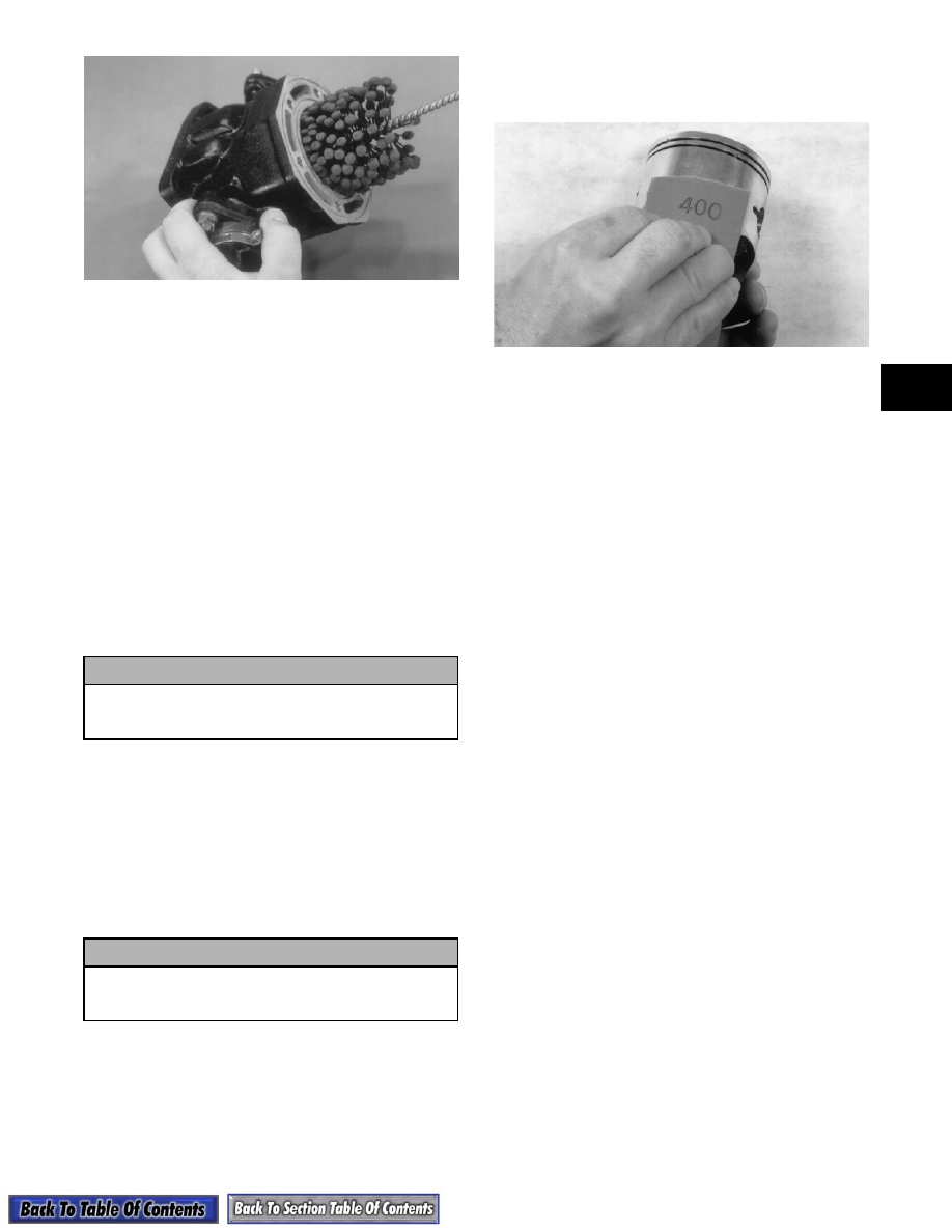
4. Inspect each piston for seizure marks or scuffing.

Repair with #400 grit wet-or-dry sandpaper and

water or honing oil.

AN135

„

NOTE: If scuffing or seizure marks are too deep

to correct with the sandpaper, it will be necessary
to replace the piston.

5. Inspect the perimeter of each piston for signs of

excessive “blowby.” Excessive “blowby” indicates

worn piston rings or an out-of-round cylinder.

CRANKCASE

1. Wash the crankcase halves in parts-cleaning

solvent.

„

NOTE: Before washing the crankcase halves,

make sure the four bearing dowel pins have been
removed and accounted for.

2. Inspect the crankcase halves for scoring, pitting,

scuffing, or any imperfections in the casting.

3. Inspect all threaded areas for damaged or stripped

threads.

4. Inspect the bearing areas for cracks or excessive

bearing movement. If evidence of excessive

bearing movement is noted, repair by peening the

bearing area in a pinking (sawtooth) pattern.

5. Inspect the bearing dowel pins for wear.

6. Inspect the sealing surfaces of the crankcase

halves for trueness by placing each crankcase half

on the surface plate covered with #400 grit wet-or-

dry sandpaper. Using light pressure, move each

half in a figure eight motion. Inspect the sealing

surfaces for any indication of high spots. A high

spot can be noted by a bright metallic finish.

Correct any high spots by continuing to move the

half in a figure eight motion until a uniform bright

metallic finish is attained.

„

NOTE: Care must be taken not to remove an

excessive amount of aluminum, or the crankcase
will have to be replaced. If excessive aluminum is
removed, too much pre-load will be exerted on the
crankshaft bearings when assembled.

! CAUTION

Water or parts-cleaning solvent must be used in
conjunction with the wet-or-dry sandpaper or
damage to the sealing surface may result.

! CAUTION

Improper cleaning of the ring-grooves by the use
of the wrong type of ring-groove cleaner will
result in severe damage to the piston.

2-60

AN060

INTAKE MANIFOLD

INSULATORS (Single Carburetor)/

ADAPTER PLATES (Twin Carburetors)

„

NOTE: For fan cooled models only.

1. Inspect for cracks, scoring, pitting, imperfections,

or warping.

2. Inspect the sealing surfaces for trueness by placing

each on the surface plate covered with #400 grit

wet-or-dry sandpaper. Using light pressure, move

both sides in a figure eight motion. Inspect the

sealing surface for any indication of high spots or

warping. Correct high spots by continuing to move

each side in a figure eight motion. Warped

components must be replaced.

„

NOTE: On the twin carburetor model in order to

inspect adapter plate trueness, it will be necessary
to remove the studs.

A932

CRANKSHAFT

1. Wash the crankshaft with bearings in parts-

cleaning solvent.

2. Inspect the bearings for wear, scoring, scuffing,

damage, or discoloration. Rotate the bearings.

Bearings must rotate freely and must not bind or

feel rough. If any abnormal condition is noted,

replace the bearing.

AN218

3. Inspect the connecting-rod bearings by rotating

them. The bearings must rotate freely and must not

bind or feel rough. If a connecting-rod bearing

must be replaced, the connecting rod and crank pin

must also be replaced.

AN217

4. Inspect the oil-injection pump drive gear for any

signs of worn or chipped teeth. If either condition

exists, replace the gear.

AQ043

! CAUTION

Water or parts-cleaning solvent must be used in
conjunction with the wet-or-dry sandpaper or
damage to the sealing surface may result.

! CAUTION

Water or parts-cleaning solvent must be used in
conjunction with the wet-or-dry sandpaper or
damage to the sealing surfaces may result.

2-61

2

„

NOTE: Lubricate bearings thoroughly prior to

assembly.

REMOVING OUTER 

CRANKSHAFT BEARINGS

„

NOTE: Steps 1-3 are for removing the MAG-side

bearing.

1. Place a bearing support (block of wood, etc.)

beneath the MAG-side bearing.

2. Drive a chisel or bearing splitter between the

bearing race and crankshaft counterweight until

the bearing is spread far enough to install the jaws

of the crankshaft bearing remover.

3. Place the protective cap on the crankshaft end;

then using the Crankshaft Bearing Remover (p/n

0144-302), remove the bearing from the end of the

crankshaft. Account for any shim(s). Note the

position of the dowel pin hole.

AQ045

4. The PTO-side bearing may be removed simply by

sliding the bearing off the PTO end.

AN151A

5. Inspect the crankshaft bearing area for wear. If any

wear is noted on either end, replace the crankshaft

end.

INSTALLING OUTER

CRANKSHAFT BEARINGS

„

NOTE: Steps 1-3 are for installing the MAG-side

bearing.

1. Wrap a thick towel around the crankshaft; then

secure the crankshaft vertically in a vise.

2. Heat the bearing either by placing the entire

bearing in a pan of oil on a hot plate or by

squirting oil into the bearing and using a propane

torch to heat the inner race of the bearing until a

slight smoke is noted coming from the bearing.

3. Place any shims removed during disassembly onto

the crankshaft; then slide the bearing onto the

crankshaft making sure the dowel-pin hole in the

outer race is properly positioned and will align

with its hole and pin in the crankcase.

4. Slide the PTO-side bearing onto the PTO end

making sure the dowel-pin hole will align with the

hole and pin in the crankcase.

AN151A

BALANCER SHAFT 

(1000 cc)

1. Inspect the balancer shaft bearings by rotating

them by hand. The bearings must rotate freely

without binding or feeling rough. If either

condition exists, replace the bearing. 

2. Inspect the balancer gear very closely for any

chipped teeth or signs of wear. If either condition

exists, replace the gear.

! WARNING

Safety glasses must be worn when spreading bear-
ings.

! CAUTION

A bearing support must be positioned beneath
the bearing that is being removed to prevent
crankshaft damage.

! CAUTION

DO NOT overheat the bearing.

2-62

AQ044

REED ASSEMBLY

1. Inspect the reed valves, stoppers, and valve blocks

for cracks or any deterioration.

AQ046

2. Wash the reed valves, stopper, and cage assembly

in parts-cleaning solvent and blow dry.

3. Inspect the reed stopper height. Using a caliper,

measure the distance from the seat to the bottom

outer tip edge of the stopper. Measurement must

not exceed specifications. If measurement is not

within specifications, either bend or replace the

reed stopper.

AJ156

4. Inspect the reed-to-seat clearance. Using a feeler

gauge, measure the clearance. Clearance must be

less than 0.20 mm (0.008 in.). If clearance is not

within specifications, replace the reed valve.

5. To assemble, place the reed valves on the cage

with its clipped corner positioned to the lower

right hand corner of the cage. Place the reed

stopper assembly into position and secure with the

three screws coated with red Loctite #271.

AQ047

Measuring Critical 

Components

„

NOTE: Critical engine component specifications

are on page 66 of this sub-section.

CYLINDER TRUENESS

1. Measure each cylinder in the three locations from

front to back and side to side for a total of six

readings.

AN302

2. The trueness (out-of-roundness) is the difference

between the highest and lowest reading.

Maximum trueness (out-of-roundness) must not

exceed specifications.


Content   ..  17  18  19  20   ..