Snowmobile Arctic Cat (2000 year). Manual - part 34
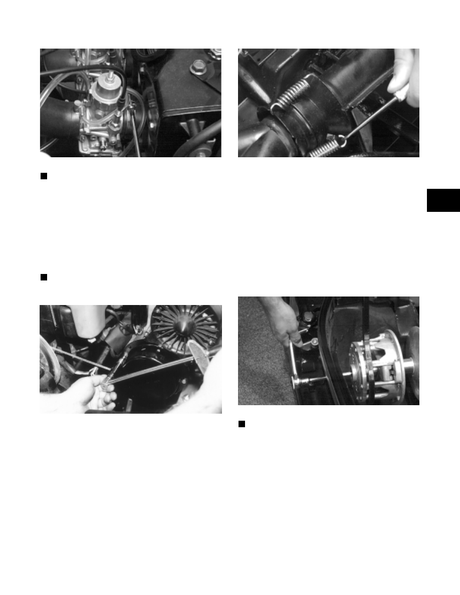
Fig. 2-440
AH283D
NOTE: At this point, check oil-injection system
synchronization (see Section 4).
8. Connect the impulse hose to the crankcase, the main
wiring harness, the CDI unit wiring harness, and the
spark plug caps.
9. Place the recoil starter into position and secure with
four cap screws and lock washers. Tighten to 0.7
kg-m (5 ft-lb) on the Bearcat models or to 1.1 kg-m
(8 ft-lb) on the Panther/Z models.
NOTE: If equipped with electric start, secure the
battery ground cable with the rear cap screw.
Fig. 2-441
AB073
10. Place the expansion chamber and grafoil gasket into
position and secure with springs.
Fig. 2-442
AB105D
11. On the Panther/Z models, place the engine mount
shims into position between the torque bumper and
engine mounting bracket; then tighten the torque
bumper jam nut.
12. On the Bearcat models, install and adjust the torque
bumper to allow a clearance between the engine and
the torque bumper of 1.5 mm (0.060 in.); then secure
the adjustment by tightening the jam nuts.
13. Place the drive clutch into position on the
crankshaft; then install the lock washer and bolt.
Tighten the clutch bolt to 6.9-7.6 kg-m (50-55 ft-lb).
Fig. 2-443
AF477D
NOTE: Apply
a
coat
of
Anti-Seize
Thread
Compound (p/n 0678-146) to the keyway end of the
driven shaft.
14. Install the driven pulley and alignment washers.
Secure with a cap screw and washer tightened to
2.6-3.3 kg-m (19-24 ft-lb).
2
2-121