Snowmobile Yamaha Phazer PZ50W, PZ50GTW, PZ50FXW, PZ50MW, PZ50VTW, PZ50MPW. Manual - part 78
8-24
–
+
ELEC
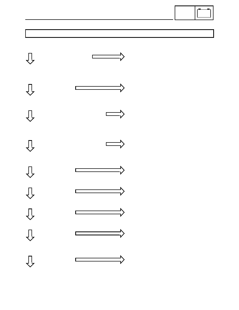
TROUBLESHOOTING
Check the headlight bulb(s).
Check the main fuse, ignition fuse, and headlight
fuse.
Refer to “FUSE INSPECTION” in CHAPTER 2.
Check the battery.
Refer to “BATTERY INSPECTION” in CHAPTER 2.
Check the stator coil.
Refer to “CHARGING SYSTEM”.
Check the engine stop switch and main switch.
Refer to “IGNITION SYSTEM”.
Check the headlight beam switch.
Check the headlight relay.
Check the load control relay.
Check the lighting system’s wiring.
Refer to “CIRCUIT DIAGRAM”.
Correct the connection and/or replace the
speedometer unit, rectifier/regulator, and/or ECU.
HEADLIGHT AND/OR HIGH BEAM INDICATOR LIGHT AND/OR METER LIGHT DO NOT COME ON.
OK
NO CONTINUITY
Replace the bulb(s).
OK
FAULTY
Replace the main fuse, ignition fuse, and/or head-
light fuse.
OK
OUT OF SPECIFICATION
Replace and/or charge the battery.
Refer to “BATTERY INSPECTION” in CHAPTER
2.
OK
OUT OF SPECIFICATION
Replace the stator coil assembly.
OK
FAULTY
Replace the right handlebar switch and/or main
switch.
OK
FAULTY
Replace the left handlebar switch.
OK
FAULTY
Replace the headlight relay.
OK
FAULTY
Replace the load control relay.
OK
FAULTY
Properly connect or repair the lighting system’s
wiring.