Snowmobile Yamaha Phazer PZ50W, PZ50GTW, PZ50FXW, PZ50MW, PZ50VTW, PZ50MPW. Manual - part 20


  Index      Snowmobiles / ATV     Snowmobile Yamaha Phazer PZ50W, PZ50GTW, PZ50FXW, PZ50MW, PZ50VTW, PZ50MPW - service manual 2007 year


Search            


Content   ..  18  19  20  21   ..


Snowmobile Yamaha Phazer PZ50W, PZ50GTW, PZ50FXW, PZ50MW, PZ50VTW, PZ50MPW. Manual - part 20


2-68

INSP

ADJ

REAR SUSPENSION

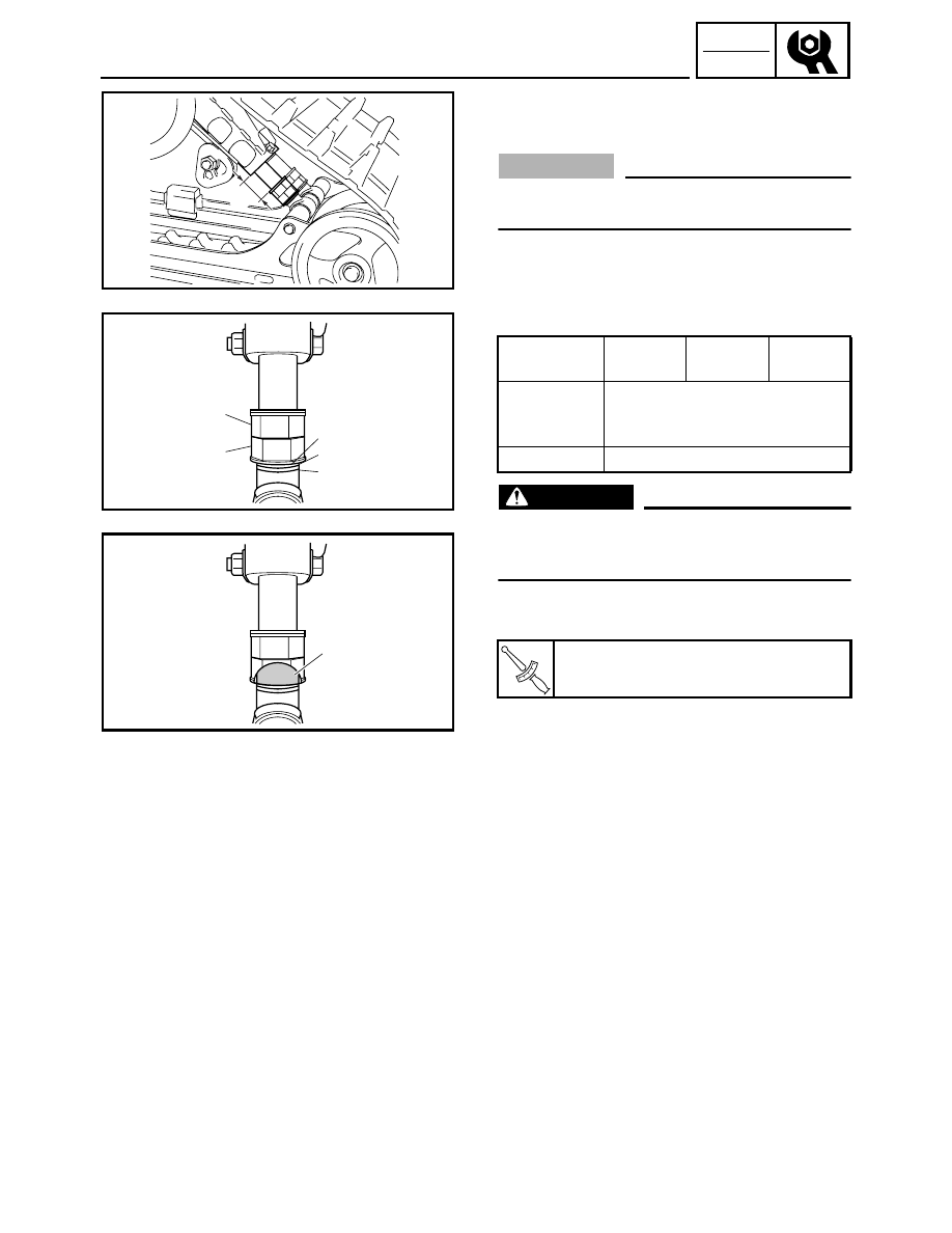
Control rod (PZ50VT/PZ50MP)

1. Adjust:

• Control rod stroke 

CAUTION:

Make sure the adjusting bolt ends are set at the
same position on each side.

Adjustment steps:

• Loosen the locknut 1.
• Turn the adjusting nut 2 in or out to adjust the

control rod stroke.

WARNING

Never adjust the control rods beyond the maxi-
mum range indicated on the rods with red paint
3.

• While holding the adjusting bolt securely,

tighten the locknut 1.

Adjusting 
position

1

2

3

Effect

Increase 
weight 
transfer

Decrease

weight

transfer

Standard

2

T


R

.

.

Locknut:

25 Nm (2.5 m · kg, 18 ft · lb)

a

3

1

2

3

1

2

2-69

INSP

ADJ

REAR SUSPENSION

2-up adjusting block (PZ50VT/PZ50MP)

1. Position:

• 2-up adjusting blocks

NOTE:

Be sure to change the position of the 2-up adjusting
blocks when there is no load (rider or cargo) on the
snowmobile.

Positioning steps:

• Pull the lock lever 1 and turn the 2-up adjusting

block until it is in the desired position.

• Release the lock lever.

NOTE:

• Make sure that the lock lever has returned to its

original position and that the 2-up adjusting block
is locked in place.

• Do not ride the snowmobile with the lock lever

pulled out.

CAUTION:

Make sure that the 2-up adjusting blocks are in
the same position on both sides of the machine.

Solo 

(rider only)

2-up 

(rider and 

passenger)

Position

A

B

Spring force

Soft

Hard

A

B

1

3-1

CHAS

CHASSIS

COWLINGS

PZ50/PZ50GT/PZ50FX/PZ50M

Order

Job name/Part name

Q’ty

Remarks

Cowling removal

Remove the parts in the order listed below.

1

Windshield

1

PZ50GT

2

Front panel

1

3

Air filter case cover

1

4

Headlight cover

1

5

Left side panel

1

6

Right side panel

1

7

Left side cover

1

8

Right side cover

1

9

Left lower cover

1

10

Right lower cover

1

11

Headlight coupler

2

12

Headlight assembly

1

13

Cylinder-#2 intake air pressure sensor cou-
pler

1

Disconnect.

7

5

4

12

6

18

3

10

2

8

17

16

11

15

13

14

8 Nm (0.8 m 

 kg, 5.8 ft 

 lb)

È:   

È

È

È

È

9

1

PZ50FX 

19

COWLINGS

3-2

CHAS

COWLINGS

Order

Job name/Part name

Q’ty

Remarks

14

Cylinder-#1 intake air pressure sensor cou-
pler

1

Disconnect.

15

Intake air temperature sensor coupler

1

Disconnect.

16

Cylinder head breather hose

1

Disconnect.

17

Oil tank breather hose

1

Disconnect.

18

Air filter case assembly

1

19

Intake air pressure sensor hose

2

For installation, reverse the removal proce-
dure.

7

5

4

12

6

18

3

10

2

8

17

16

11

15

13

14

8 Nm (0.8 m 

 kg, 5.8 ft 

 lb)

È:   

È

È

È

È

9

1

PZ50FX 

19

3


Content   ..  18  19  20  21   ..