Snowmobile Yamaha Phazer PZ50W, PZ50GTW, PZ50FXW, PZ50MW, PZ50VTW, PZ50MPW. Manual - part 5
2-8
INSP
ADJ
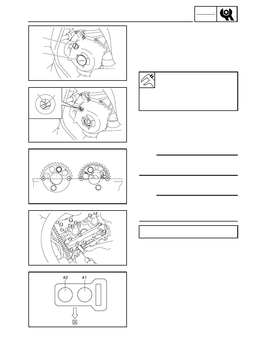
3. Remove:
• Cylinder head cover
Refer to “CAMSHAFTS” in CHAPTER 5.
• Timing mark accessing screw 1
• Crankshaft end accessing screw 2
4. Measure:
• Valve clearance
Out of specification
→ Adjust.
Checking steps:
• Turn the crankshaft counterclockwise.
• When piston #1 is at TDC on the compression
stroke, align the TDC mark
a on the A.C. mag-
neto rotor with the mark
b on the A.C. magneto
cover.
NOTE:
TDC on the compression stroke can be found when
the camshaft lobes are turned away from each
other.
• Measure the valve clearance with a thickness
gauge 1.
NOTE:
• If the valve clearance is incorrect, record the
measured reading.
• Measure the valve clearance in the following
sequence.
• Turn the crankshaft 180° counterclockwise and
check the valve clearance of piston #2.
È Front
Valve clearance (cold):
Intake valve:
0.11 ~ 0.20 mm
(0.0043 ~ 0.0079 in)
Exhaust valve:
0.21 ~ 0.25 mm
(0.0083 ~ 0.0098 in)
Valve clearance measuring sequence
Cylinder #1
→ #2
1
2
a
b
1