Snowmobile Yamaha FX10X, FX10RTX, FX10RTRX, FX10RTRAX, FX10MTX, FX10MTRX, FX10MTRAX. Manual - part 73
7-22
FI
Fault code No.
43
Symptom
Power supply to the fuel injectors and fuel pump is not normal.
Diagnostic code No. 09 (fuel system voltage)
Order
Item/components and probable cause
Check or maintenance job
Reinstatement
method
1
Connections
Fuel injection system relay coupler
Wire harness ECU coupler
Check the couplers for any pins that may have
pulled out.
Check the locking condition of the couplers.
If there is a malfunction, repair it and connect the
coupler securely.
Starting the
engine and
operating it at
idle.
2
Open or short circuit in wire harness.
Repair or replace if there is an open or short cir-
cuit.
Between the fuel injection system relay coupler
and ECU coupler.
Blue/Red – Blue/Red
Between the fuel injection system relay coupler
and engine stop switch coupler.
Red/White – Red/White
Between the engine stop switch coupler and main
switch coupler.
Brown – Brown
3
Malfunction or open circuit in fuel injec-
tion system relay.
Execute the diagnostic mode (code No. 09).
Replace if defective.
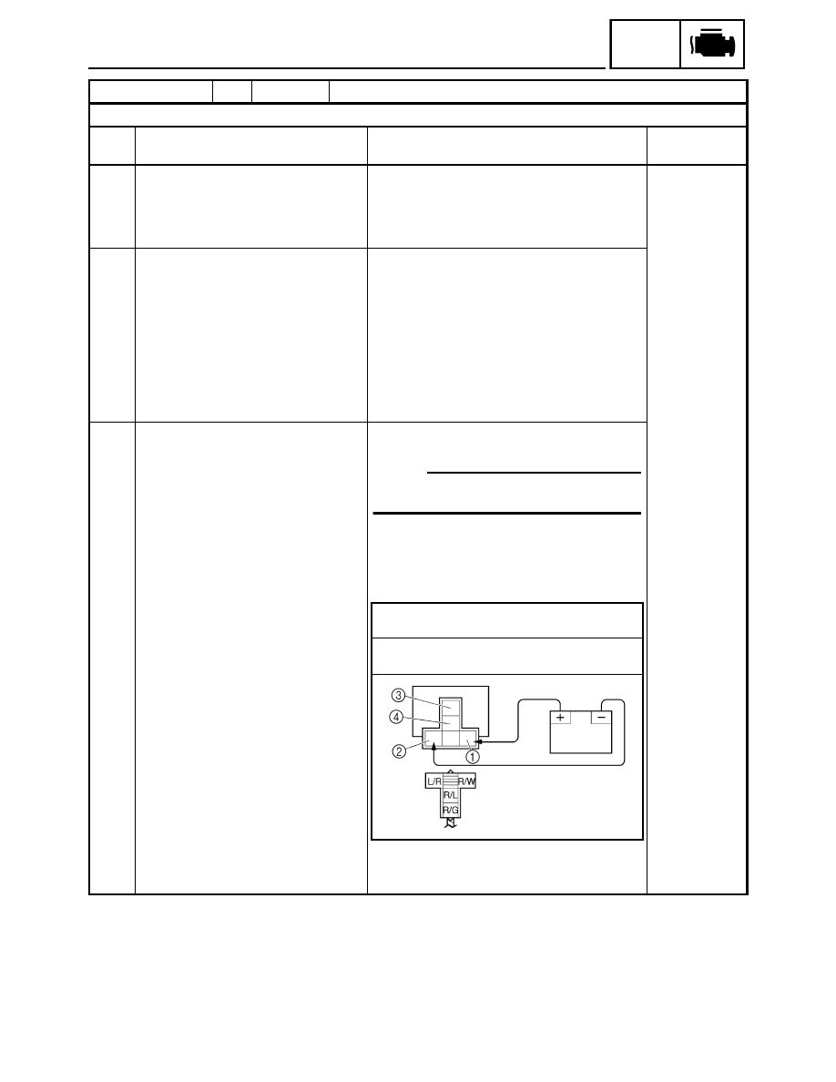
NOTE:
When the leads are disconnected, the voltage
check by the code No. 09 is impossible.
1. Disconnect the fuel injection system relay from
the wire harness and remove it.
2. Connect the pocket tester (
Ω × 1) and battery
(12 V) to the fuel injection system relay termi-
nals as shown.
3. Does the fuel injection system relay have con-
tinuity between the red/green and red/blue ter-
minals?
Positive battery terminal
→ Red/White 1
Negative battery terminal
→ Blue/Red 2
Positive tester probe
→ Red/Green 3
Negative tester probe
→ Red/Blue 4