Snowmobile Polaris 600 RUSH (2010 year). Manual - part 20


  Index      Snowmobiles / ATV     Snowmobile Polaris 600 RUSH - service manual 2010 year


Search            


Content   ..  18  19  20  21   ..


Snowmobile Polaris 600 RUSH (2010 year). Manual - part 20


3.30

Engine/Cooling/Exhaust

9923311 - 2010-2012 PRO-RIDE RUSH/Switchback/RMK Service Manual

© 2011 Polaris Sales Inc.

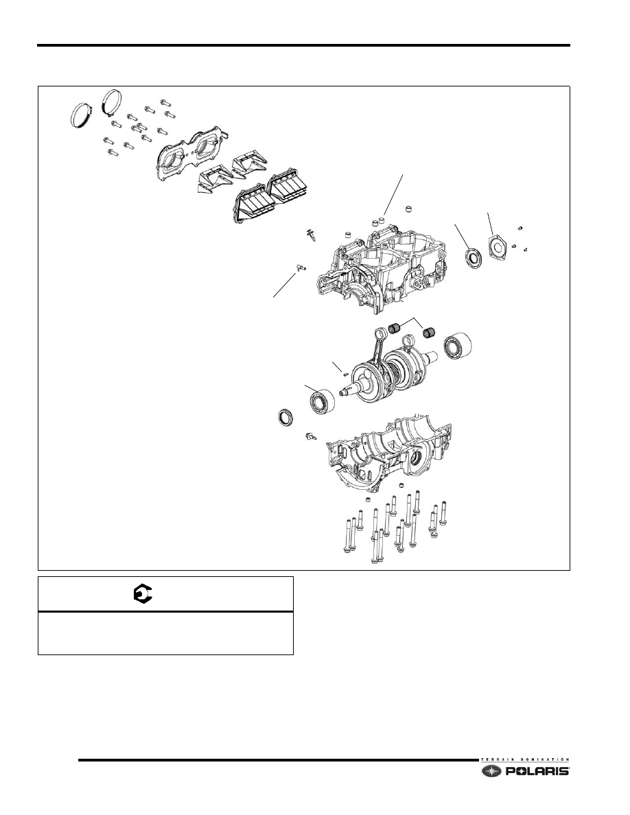
800 DC-CFI-2 Crankcase/Crankshaft

GEAR CLAMPS

ADAPTER PLATE

REED STUFFERS

REED BLOCKS

SEAL GUARD

PTO SEAL

ALIGNMENT DOWELS

MAG SEAL

MAG BEARING

FLYWHEEL KEY

PTO BEARING

WRIST PIN BEARINGS

OIL INJECTION CHECK VALVE QTY. 5

ALIGNMENT DOWELS

A

B

C

STATOR WIRE RETAINER

STATOR WIRE RETAINER

T 

A: 9 ft-lb (12 Nm)

B: 22 ft-lb (30 Nm) - Apply Loctite® 242™

C: 10 ft-lb (13 Nm) - Apply Pipe Sealant

3.31

Engine/Cooling/Exhaust

3

9923311 - 2010-2012 PRO-RIDE RUSH/Switchback/RMK Service Manual

© 2011 Polaris Sales Inc.

Disassembly and Assembly Process - Crankcase/
Crankshaft

1.

Remove the engine from the engine compartment. 

2.

Follow the process for removing the cylinder head, 
cylinders, pistons, flywheel/recoil housing, and the 
water/oil pump.

NOTE:  The crankcase ring land damage shown in the 
corresponding photo is caused by improper 
crankcase separation or crankshaft removal.

3.

Remove all crankcase fasteners except ones marked 
5-6-7-8 indicated below. Loosen these 4 bolts to 
reveal about a 1/6"-1/8" bolt gap.

4.

Once loosened, carefully and lightly tap on the bolts 
to separate the crankcase halves.

5.

Discard the PTO and MAG crankshaft seals.

6.

Remove the crankshaft by pulling it straight up and 
out. Inspect as required.

7.

Thoroughly clean the two crankcase mating surfaces 
with carburetor cleaner and a gasket remover. Flush 
out the crankcase galleries.

8.

Reinstall the crankshaft back into the lower crankcase 
using two new crankcase seals.

9.

Apply a thin bead of Three Bond 1217H to the lower 
crankcase mating surface. Install the upper 
crankcase.

NOTE:  Do not over-apply sealant in oil injector area. 
Doing so may block the oil passage.

10. Loosely install the crankcase fasteners, then torque to 

the specifications at the beginning of the chapter. Use 
the correct torque sequence when tightening the 
screws.

11. Liberally coat the crankshaft bearings and 

components with Polaris two-stroke engine oil.

800 DC-CFI-2 Crankshaft Identification

Two different crankshaft assemblies (Type 1 and Type 2) 
are used for production and service parts. Use the codes 
etched into the nose of the PTO end to determine 
crankshaft type when ordering service parts.

Type 1 will have the number 3753. Type 2 will have the 
number 0262.

DO NOT FILL MAG 

BEARING OIL 

GALLERY WITH 

CASE SEALANT

DOWELS

3.32

Engine/Cooling/Exhaust

9923311 - 2010-2012 PRO-RIDE RUSH/Switchback/RMK Service Manual

© 2011 Polaris Sales Inc.

600/800 DC-CFI Water and Oil Pump 

Assembly

OIL PUMP

BEARING

CROSS SHAFT

WASHER

WASHER

O-RING

SEAL

MECHANICAL SEAL

WASHER

IMPELLER

NUT

WASTER PUMP COVER GASKET

WASTER PUMP COVER

B

A

C

A

T 

A: 10 ft-lb (13 Nm)

B: 9 ft-lb (12 Nm)

C: 18 ft-lb (Nm) Apply pipe sealant.

3.33

Engine/Cooling/Exhaust

3

9923311 - 2010-2012 PRO-RIDE RUSH/Switchback/RMK Service Manual

© 2011 Polaris Sales Inc.

Disassembly / Assembly Process

IMPORTANT: Use the mechanical seal installation 
tool to install the water pump seal, PN: 2872010.

1.

Remove the coolant from the engine using a siphon, 
wet/dry vac. or a drain pan.

2.

Remove the oil tank/clutch cover assembly, airbox, 
exhaust pipe and resonator. Remove the hoses 
connected to the water pump cover.

3.

To access the impeller and mechanical seal, remove 
the water pump cover. Discard the water pump cover 
gasket.

4.

Remove the impeller nut, impeller and washers from 
the cross shaft.

5.

Carefully pry the mechanical seal and seal out of the 
crankcase.

6.

Water pump assembly is the reverse of disassembly. 
Always use new seals and gaskets during assembly.

7.

To remove the oil pump, the engine must be removed 
from the engine compartment. Remove the two 
fasteners then pull the pump out of the crankcase 
bore. Discard the o-ring.

8.

The cross shaft can be extracted from the water pump 
side of the crankcase.

9.

Assembly is the reverse of disassembly. Always use 
new o-rings, seals and gaskets during assembly.

10. Install a new seal onto the shaft from the water pump 

side.

11. To install a new water pump seal, use the seal 

installation tool, PN 2872010. Verify the seal lips are 
facing the cross shaft gear.


Content   ..  18  19  20  21   ..