Snowmobile Polaris Two Stroke (2007 year). Manual - part 58


  Index      Snowmobiles / ATV     Snowmobile Polaris Two Stroke - service manual 2007 year


Search            


Content   ..  56  57  58  59   ..


Snowmobile Polaris Two Stroke (2007 year). Manual - part 58


9.15

REAR SUSPENSION

9

IMPORTANT: The M-10 rear suspension has been

designed to be very sensitive to rider weight. Changes

in rider weight of 25 lbs. or more may require

appropriate changes in FRA settings.

M-10 Terminology

• Couple Blocks: Plastic blocks located at the rear of 

each rail. Blocks facilitate the couple function.

• Full Range Adjuster (FRA): FRA refers to the 

adjustable lower rear shock attachments. Changing the 
FRA location has two effects on tuning. First, moving 
the shock forward increases shock speed, resulting in 
firmer damping on compression and rebound. Second, 
it also increases the effect of the rear spring by 
displacing it further.

• Sag Settings: The difference in rear bumper height 

from the sleds fully extended position to its lower 
height with the rider seated on the sled.

M-10 Adjustments

The primary adjustment on the M-10 suspension is the Full
Range Adjustment (FRA). Adjusting the FRA will have to
MOST effect on rear suspension performance.

Polaris recommends that you allow between 25 to 200 miles for
the suspension to break in before performing any adjustments to
the suspension.

This chart is a guideline to be used for initial suspension setups.
Your setup may vary based on your desired riding style.

*=You may prefer an optional rear track middle spring retainer.
See “Optional Retainers” on page 9.16.

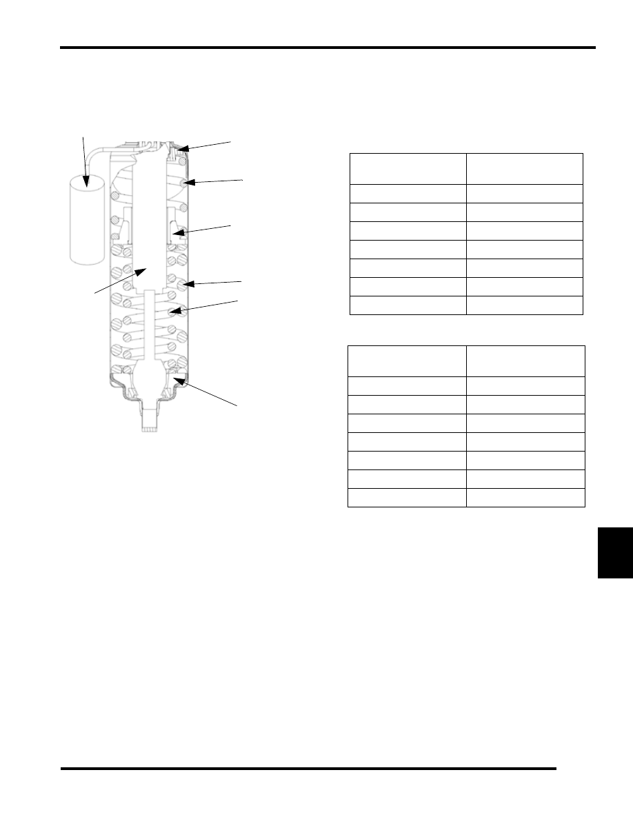
Lower Spring Retainer

Upper Spring Retainer

Center Retainer

Reservoir

Shock

Outer Spring

Inner Spring

Upper Spring

M-10 128

Rider weight with gear 
(lbs.)

Suggested FRA Range 
(Lower number is softer)

Under 100

1 to 1 1/2

100-150

1 1/2 to 2

150-200

2 to 2 1/2

200-250

2 1/2 to 3

250-300

3 to 3 1/2

300-350*

3 1/2 to 4

Over 350*

4 to 5

M-10 136

Rider weight with gear 
(lbs.)

Suggested FRA Range 
(Lower number is softer)

Under 100*

1 to 1 1/2

100-150*

1 1/2 to 2

150-200*

2 to 2 1/2

200-250

2 1/2 to 3

250-300

3 to 3 1/2

300-350

3 1/2 to 4

Over 350

4 to 5

9.16

REAR SUSPENSION

M-10 FRA Initial Set Up Reference

The FRA setting is the primary rear suspension adjustment. It
will have the MOST effect on the rear suspension performance.
To adjust the FRA:.

1.

Refer to the initial set-up reference chart to determine the
desired FRA position.

2.

To adjust, loosen the hex bolts attaching the rear lower
shock cross shaft to the rail beam.

3.

Using a 9/16" wrench, loosen the jam nuts on the preload
bolts.

4.

Adjust the preload bolts to the desired FRA position.

5.

Tighten the jam nuts.

NOTE:  Make sure the preload bolt contacts the slide
block before tightening the jam nut.

6.

Tighten the hex bolts and torque to 35 ft. lbs. (47 N-m)

NOTE:  When the M-10 suspension is new, it will take
from 25 to 200 miles (40-300 km) to properly break in
the springs and shocks, at which time the
suspension will be softer and may require FRA re-
adjustment.

M-10 Rear Spring Preload

If FRA position alone does not allow the setup of the proper
amount of sag, the center retainer of the rear track shock can be
replaced with optional retainers to adjust the preload and change
the sag. 

NOTE:  Whenever ordering any of the retainers listed
in the chart, always order the retainer insert as well.
The insert is not removable once installed, so a new
insert is needed when installing a new retainer.

M-10 Ski Pressure

Ski pressure is set at the factory to deliver the optimum balance
between ride and handling. If a rider prefers more ski pressure
for improved steering performance, adjustments can be made to
the front limiter strap and front arm mount.

1.

Determine if the rider prefers comfort or control. Lean
toward the #4 setting for comfort and toward the #3 setting
for aggressive riding.

2.

For full hole adjustments, remove the 5/16" nut and flat
washers from the lower attachments of the limiter straps
and relocate the straps to the desired position (i.e. move
from position 4 to 3). Replace the nut and washer. Tighten
securely.

3.

For half-hole increments (such as hole 3 or 4), the limiter
straps have slots at the upper pinch bolt. These slots allow
the bolts to be loosened (rather than removed) for half-step
adjustments. Re-tighten the pinch bolts.

4.

There are also two front arm mounting holes in the slide rail
that can adjust ski pressure. The lower hole (A) increases

Optional Retainers

Retainer insert 

Part Number

Retainer part 

Number

Preload

Sag

5436109

5135077 (std. on 

M10/128)

Least

Most

5134923

Middle

Middle

5135080 (std. on 

M10/136)

Most Least

1

4

2

3

2

3

4

9.17

REAR SUSPENSION

9

ski pressure while the upper hole (B) decreases ski pressure.

NOTE: By design, the BIASED COUPLE design of
the M-10 suspension displaces the rear arm as the
front arm is compressed. This means that when you
raise the front limiter strap, at some point you will
collapse the rear suspension arm, which will affect
SAG height and reduce rear suspension travel.

RAIL SLIDER

Rail Slide Wear Limit

Hi-Fax replacement on all Polaris models is similar. When any
area of the Hi-Fax is worn to the wear indicator (A), it should be
replaced. This will save wear on other vital components on the
suspension.

The slide rail is designed to operate in conditions with adequate
snow cover to provide sufficient lubrication. Excessive wear
may be due to improper alignment, improper track adjustment
or machine operation on surfaces without snow.

Rail Slide Removal

1.

Remove the rear suspension.

NOTE:  Some models may allow the rail sliders to be
removed by sliding it through track windows with
the suspension mounted in the machine.

2.

Remove front rail slider retaining bolt, located at the rail tip.

3.

Use a block of wood or a drift punch and hammer to drive
the Hi-Fax rearward off the slide rail.

4.

With the rail slider at room temperature, install a new rail
slider by reversing steps 1 - 3.

NOTE: Lightly coat rail slider track clip area with a
lubricant such as LPS2 or WD-40 to ease installation.

Rail Slider Break In

After installing new rail sliders they must be “broke in” for
longer life and better wear patterns. When performing the
breaking in procedure ride the sled on a surface that has
adequate snow conditions with deeper snow nearby. Run the
sled on the adequate snow surface and dip into the deeper snow
every so often.

A

B

A

9.18

REAR SUSPENSION

REAR SUSPENSION REMOVAL / 
INSTALLATION

Rear Suspension Removal

1

1

2

3

2

3

2

3

1

2

3

4

5

1

2

3

6

1

2

3

7

8

9

10

11


Content   ..  56  57  58  59   ..