Snowmobile Polaris (2006 year). Manual - part 18


  Index      Snowmobiles / ATV     Snowmobile Polaris - service manual 2006 year


Search            


Content   ..  16  17  18  19   ..


Snowmobile Polaris (2006 year). Manual - part 18


3.8

MAINTENANCE

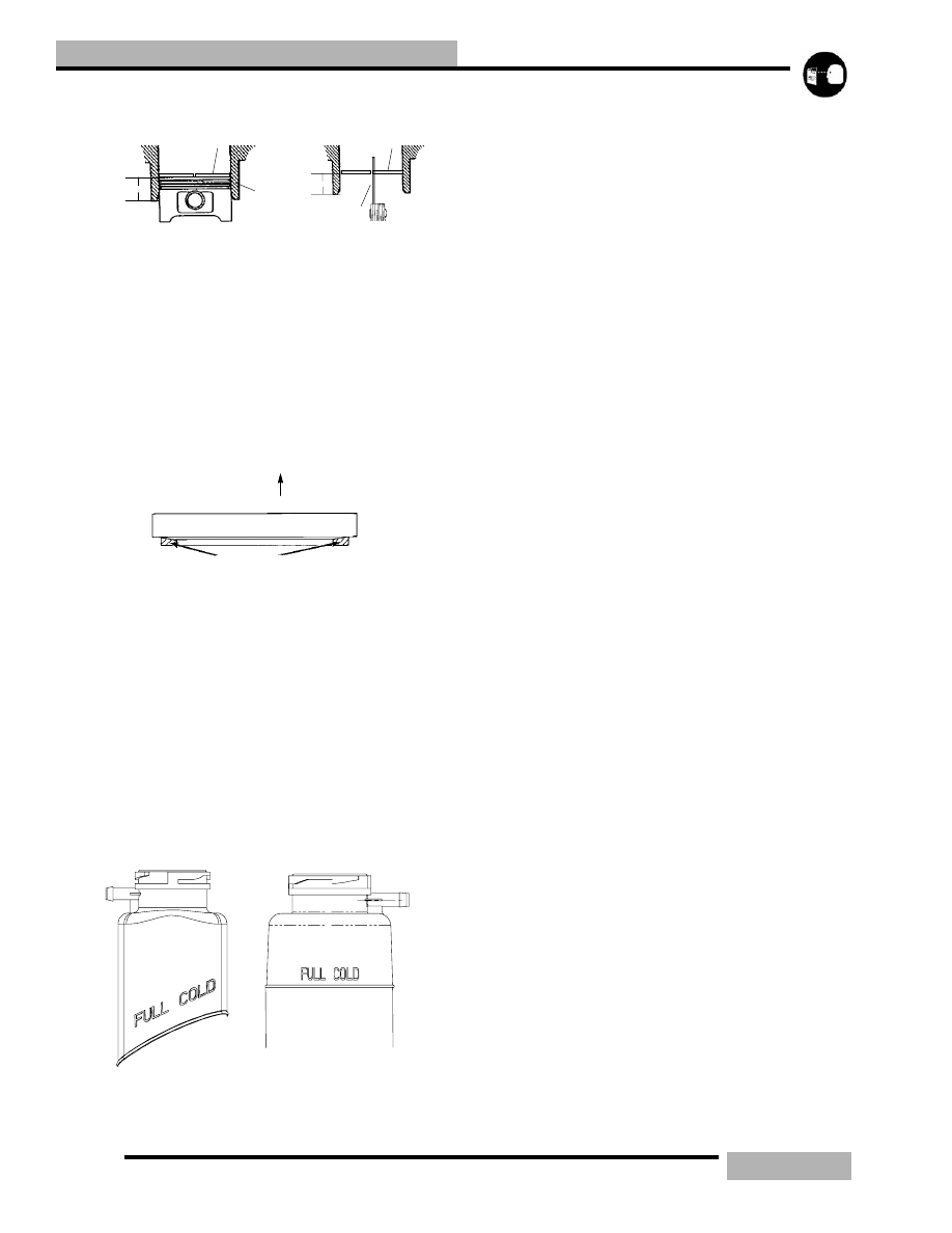
PISTON RING INSTALLED GAP

Position the ring 1/2" (1.3 cm) from the top of the cylinder 
using the piston to push it squarely into place. Measure 
installed gap with a feeler gauge at both the top and bottom of 
the cylinder.

NOTE:  A difference in end gap indicates cylinder 
taper. The cylinder should be measured for 
excessive taper and out of round. Replace rings if 
the installed end gap exceeds the service limit. 
Always check piston ring installed gap after re-
boring a cylinder or when installing new rings.

Piston rings are installed with marking or beveled side up see 
diagram above.

COOLANT LEVEL

Coolant level in the coolant bottle must be maintained to 
prevent overheating and serious engine damage. Check the 
coolant with the engine temperature cold. The coolant level 
should be at the FULL COLD level mark. If it is not add 
coolant to the FULL COLD mark on the bottle. If you have 
coolant over the FULL COLD level you may have air in the 
system and need to “bleed” the air out of the system.

RECOMMENDED COOLANT

Polaris snowmobiles use a premium 60/40 pre-mix antifreeze. 
This premium antifreeze is mixed with deionized water for 
better protection for aluminum cooling. This pre-mix is good 
for temperatures down to -62_F (-52_C). Replace coolant 
every 2 years or if contaminated.

• 60/40 Pre-mix Quart PN 2871534

• 60/40 Pre-mix Gallon PN 2871323

• 60/40 Pre-mix 2.5 Gallon PN 2872278

COOLING SYSTEM BLEEDING

1.

Allow the cooling system to cool completely.

2.

Check the coolant reservoir and make sure it is at the
FULL COLD mark.

3.

Place the snowmobile in its normal riding position and
apply the parking brake and run the engine at the specified
idle RPM until the thermostat opens up.

4.

Open the bleed screw (A) at the top of the water outlet

Piston Ring

Feeler Gauge

1/2

s (1.3cm.)

1/2

s (1.3cm.)

Cylinder

Piston Ring

Straight Edge

Keystone Piston Ring Cutaway

Up

3.9

MAINTENANCE

manifold.Only open slightly, do not remove the screw.

5.

Cycle the RPM from idle to 3000-4000 so that the coolant
can move around the system and push out the air from the
system.

6.

Tighten the bleed screw when coolant starts to come out of
the screw area.

7.

Turn off the machine and release the parking brake.

8.

Allow the system to cool completely and recheck the
coolant level.

NOTE:  It is important that the thermostat stays 
open! When the thermostat opens it will draw in cold 
coolant from the heat exchangers and the cold 
coolant may close the thermostat again. Make sure 
the thermostat opens and stays open! Cycle the 
RPM from idle to enough RPM (4000) to get coolant 
to flow but not enough RPM to engage the clutch. 
This allows air to bleed from the rear crossover tube. 
It is important to get enough coolant flow to purge 
the air from the front close-off cooler and observe 
this air reaching the bottle.

NOTE:  ON EDGE MODELS: Once the thermostat is 
open tip the snowmobile slightly on its right side 
and cycle the RPM from idle to enough RPM (4000) 
to get coolant to flow but not enough RPM to engage 
the clutch. Then tilt the machine slightly on its left 
side so that the coolant bottle is the highest point in 
the cooling system and cycle the RPM from idle to 
enough RPM (4000) to get coolant to flow but not 
enough RPM to engage the clutch.

BEARING FIT

Any time crankshaft bearing failure occurs and the case is to 
be reused, Polaris recommends checking the bearing fit into 
the case halves using the following procedure.

With case halves cleaned, press a replacement bearing into 
each of the main bearing journals to determine a basic amount 
of press fit.

Do a comparison check of all journals by manually forcing the 
bearing into the bearing seats noting if any are noticeably 
loose or tight. Normal hand installation will be an indication of 
the recommended interference fit. If the bearing falls out of the 
case when the case is inverted, or if the crankcase bearing 
surface is severely galled or damaged, the case should be 
replaced.

NOTE:  Crankcase bearing interference fit is .001-
.002
" (.026-.051mm).

500 Fuji

700/900 Libertyt

500/600 Libertyt

WARNING

When performing the following checks and adjust-

ments, stay clear of all moving parts to avoid

serious personal injury. Never remove the pressure 

cap when the engine is warm or hot. If the pressure 

cap is to be removed, the engine must be cool. Se-

vere personal injury could result from stream or hot 

liquid.

3.10

MAINTENANCE

MAIN BEARING

Clean crankshaft thoroughly and oil main and connecting rod 
bearings with Polaris engine oil. Carefully check each main 
bearing on the shaft.

Due to extremely close tolerances, the bearings must be 
inspected visually, and by feel. Look for signs of 
discoloration, scoring or galling. Turn the outer race of each 
bearing. The bearings should turn smoothly and quietly. The 
inner race of each bearing should fit tightly on the crankshaft. 
The outer race should be firm with minimal side to side 
movement and no detectable up and down movement. Replace 
any loose or rough bearings.

CONNECTING ROD (BIG END) BEARING

Specialized equipment and a sound knowledge of crankshaft 
repair and straightening is required to perform crankshaft 
work safely and correctly. Crankshaft repair should be 
performed by trained Polaris service technicians in a properly 
equipped shop.

Measure connecting rod big end side clearance with a feeler 
gauge. 500/600 Libertyt engines should have a clearance of 
.011 - .030" (.28 -.75mm) and 700/800/900 Libertyt 
engines should have .011 - .028" (.28 - .70mm) and be equal 
on all rods within .002" (.05mm).

Rotate the connecting rod on the crankshaft and feel for any 
rough spots. Check radial end play in rod by supporting rod 
against one thrust washer and alternately applying up and 
down pressure. Replace bearing, pin, and thrust washers if 

side clearance is excessive or if there is any up and down 
movement detectable in the big end bearing.

WRIST PIN BEARING

1.

Clean the end of the connecting rod and inspect inner bore
with a magnifying glass. Look for any surface
irregularities including pitting, wear, or dents.

2.

Run you fingernail around the inside of the rod and check
for rough spots, galling, or wear.

3.

Oil and install needle bearing and pin in connecting rod.

4.

Rotate pin slowly and check for rough spots or any
resistance to movement.

5.

Slide pin back and forth through bearing while rotating
and check for rough spots.

6.

With pin and bearing centered in rod, twist ends back and
forth in all directions to check for excessive axial play.

7.

Pull up and down evenly on both ends of pin to check for
radial play.

8.

Replace pin and bearing if there is any resistance to
rotation or excessive axial or radial movement. If play or
roughness is evident with a new pin and bearing, replace
the connecting rod.

Within .002” (.05mm)

NEEDLE BEARING

3.11

MAINTENANCE

CRANKSHAFT INDEXING

Polaris uses crankshafts that are pressed together. The 
connecting rod journal center lines are indexed 180_(twins).

It is sometimes necessary to check multi-cylinder crankshafts 
to verify that one cylinder has not been forced out of position 
relative to the other cylinder. Some causes for a “out of index” 
crankshaft include but ar not limited to the following:

• Hydraulock from water or fuel

• Impact to drive clutch from object or accident

• Abrupt piston or other mechanical failure

• Engine lock-up due to drive belt failure

CHECKING CRANKSHAFT INDEX

1.

Remove the drive belt, see DRIVE BELT in Chapter 7.

2.

Remove the drive clutch, see “DRIVE CLUTCH
REMOVAL” on page 7.10.

3.

Securely fasten a large degree wheel on the flywheel or
PTO end of the crankshaft. Make sure that it is mounted
concentrically with the crankshaft center line. 

4.

With a section of wire (wire coat hanger), anchor it to a
convenient spot. Bend one end at the outer perimeter of the
degree wheel as shown above.

5.

Install a dial indicator into the magneto end cylinder spark
plug hole. The ignition timing is referenced by the
magneto end.

6.

Locate TDC as accurately as possible by finding the center
of the point where there is no piston movement note the
”Zero” the dial indicator at this point.

7.

Continue to rotate the crankshaft in the normal direction of
rotation until the dial indicator reads .100" (2.54mm) after
top dead center (ATDC).

8.

Bend the pointer or move the degree wheel until the
pointer aligns with a 180_ mark on the degree wheel.

9.

With the pointer aligned, make sure the degree wheel and
pointer are secured and will not move out of position. Re-
check accuracy of this location a few times. The pointer
should align with the 180_ mark when the dial indicator
reads .100” (2.54mm) ATDC.

NOTE:  Do not move the crankshaft, degree wheel or 
pointer after the initial setting on the MAG end 
cylinder - simply read the wheel and dial indicator.

10. Remove the dial indicator and install in PTO cylinder.

Repeat finding TDC. Note the degree wheel indication
when the dial indicator reads .100" ATDC. It should be
180_ (+/-2_) from the MAG cylinder mark.

Symptoms of an out of index crankshaft can include but are 
not limited to the following:

• Difficulty calibrating carburetor (repetitive plug fouling 

on one cylinder with no other cause)

• Unexplained piston failure on one cylinder (i.e. severe 

detonation, broken ring lands, piston holing)

• Excessive vibration of engine, back firing, etc.

• Rough idle, poor top speed.

CRANKSHAFT TRUING

Lubricate the bearings and clamp the crankshaft securely in 
the holding fixture.If truing the crankshaft requires striking 
with a hammer, always be sure to re-check previously 
straightened areas to verify truing. Refer to the illustrations 
below. Use Crankshaft alignment kit PN 2870569.

CAUTION

Disconnect the battery ground cable and ALL spark

plug high tension leads. Ground high tension leads to

the engine. Disconnect lanyard (if equipped) and/or

press the engine stop switch before proceeding with

the following procedure.

Dial Indicator

Degree
Wheel

.100 ATDC

Crankshaft center line

Dial Indicator

Degree
Wheel

.100 ATDC

MAG

PTO


Content   ..  16  17  18  19   ..