Snowmobile Polaris (2006 year). Manual - part 17
3.4
MAINTENANCE
Brake Disc
I
I
I
I
Parking Brakes
I
I
I
I
I
Brake System
I
Brake Fluid
R
FUEL MANAGEMENT
Pilot Air Screws
I
I
I
Carburetor
(synchronize)
I
I
I
Idle RPM
I
I
I
Throttle Lever
I
I
I
I
I
Oil Pump Lever
(synchronize)
I
I
I
Throttle Cable
L
L
L
Choke Cable
L
L
L
Choke
I
I
I
Vent Lines
I
I
I
I
Throttle Position
Sensor
I
I
I
Fuel Lines
I
I
I
I
I
Fuel Filter
R
R
Oil Filter
R
R
Oil Lines
I
I
I
Air Box
I
I
I
I
I
Drain and Water Traps
I
I
I
ELECTRICAL
Auxiliary Shut-Off Switch
I
I
I
I
I
I
Throttle Safety Switch
I
I
I
I
I
I
Ignition Switch
I
I
I
I
I
I
Taillight
I
I
I
I
I
I
Brakelight
I
I
I
I
I
I
Headlight
I
I
I
I
I
I
Tether Switch and Strap
I
I
I
I
I
I
CHASSIS
Ski Toe Alignment
I
I
I
Suspension Mounting Bolts
I
I
I
I
I
I
Steering Fasteners
I
I
I
I
C
Rear Suspension Fasteners
I
I
I
I
I
Suspension Shock Oil
I
I
I
I
Cooling Fins and Shroud
I
I
I
I
Drive Shaft Bearing
L
L
L
I
Jackshaft Bearings
L
L
L
I
Skags (Wear Bars)
I
I
I
I
I
I
Ski Saddle/Spindle Bolts
I
I
I
I
I
I
Drive Chain Tension
I
I
I
I
I
Hood Straps
I
I
I
I
I
I
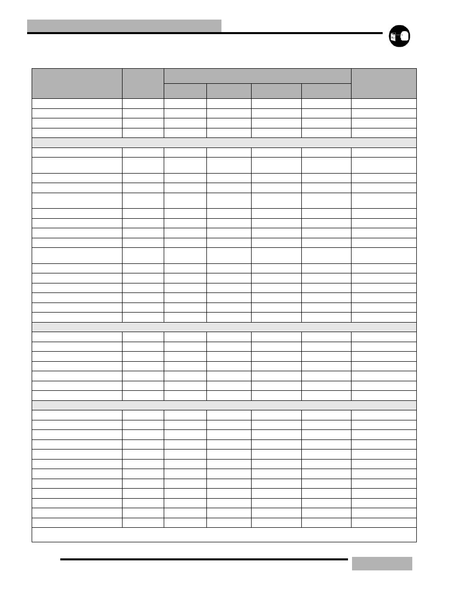
Table 3-1: Maintenance Intervals
Item
Pre-Ride
Frequency Miles (km)
Pre-
Season
150 (240)
500 (240)
1000 (1600)
2000 (3200)
I:Inspect (clean, adjust, tighten, lubricate, replace if necessary) C:Clean R:Replace L:Lubricate