Kincaid 8xp. Manual - part 14
 

  Index      Combines     Kincaid 8xp Combine Harvester - service manual 2012 year


Search            


Content   ..  12  13  14  15   ..


Kincaid 8xp. Manual - part 14


- 59 -

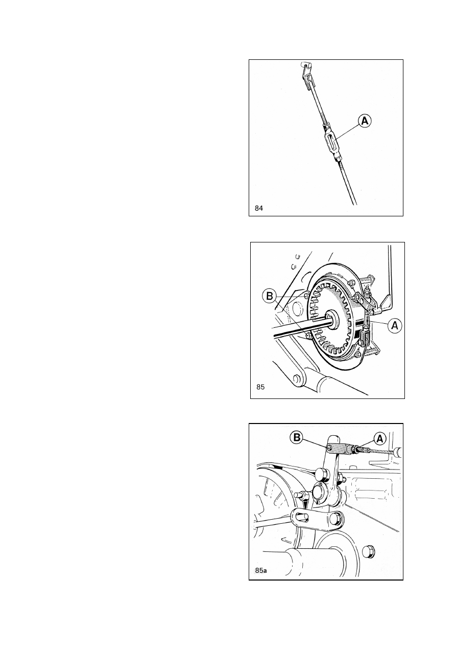
Adjustment of Driving Brakes

(Fig. 84 and 85)

The brakes must be adjusted occasionally 

due to wear of the brake bands. The free 

travel of the pedals has to be 20 to 40 

mm. To adjust screw turnbuckles A, Fig. 

84, on both sides of the machine. It is very 

important that the free travel of the pedals is 

equal so that the brakes latched together do 

not veer.

Do the basic adjustment of the brakes by

screw A, Fig. 85. Centre the brake shoes 

relative to the brake drums by eccentric 

screws B, for instance after changing the 

brake bands.

Adjustment of Hand Brake

The free travel of the hand lever on the

toothed arch must not exeed 5…6 teeth. It

is adjuted at lower edge of the wire.

To adjust, slacken lock nut A, Fig 85a,

loosen pin B of the fork and by rotating the

fork adjust the direction as required. After

adjusting lock the joints.

Heating, Ventilation and Air

Conditioning of the Cabin

Filters have to be cleaned daily. The best 

way is to use air blast for cleaning. The 

outer filter element can be also washed 

when needed. The paper element must be 

replaced before every harvesting season.

The condenser core of the air conditioning

located to right side of the engine 

compartment may be necessary to clean 

daily, especially in dust conditions. Blow with 

air blast from inside. 

Remove chaff from the bottom

door of screen chamber. Be careful, do not

damage the radiator core.

At least ones a year and more often in dusty

conditions it is necessary to clean heating

and cooling cores, air channels and ventilator

fan. This is best to do through access door 

at top of the cabin by air blast or a vacuum 

cleaner.

87a

- 60 -

Checking of Substitute of Air

Conditioning (Fig. 86)

Checking have to be done before every 

harvesting season. New environment friendly 

R134a substitute is more sense to leak as 

previous one. This may happen especially 

when combine stands unused for longer 

period. Some leakage through the shaft 

sealing is normal.

Checking will be done by engaging cooling

to operate with full effect. Observe little

eye-glass at the top of drier cartridge. ,Fig

86 . There should not flow gas bulbs except

just after compressor engaging. The drier

cartridge have been placed to the right side

of engine compartment in hose coming from

condenser to cabin.

In case if needed, the filling of air 

conditioning have to be done by authorised 

service company. Only R134a substitute can 

be added.

Engine (Fig 87a)

(Read the engine instruction manual for

more precise maintenance instructions)

Oil Change at least After Each

Harvesting Season

Change the oil at intervals shown in engine

instruction book and with each

winter storage.

The oil has to be drained by an electrical 

suction pump through the engine dipstick 

hole (Fig 87a) as follows:

•  Run the engine until the oil 

reach its normal temperature 

(+40…50°C/105…125 F) 

•  Pull out the engine oil dipstick

•  Insert the suction hose into the oil 

dipstick tube and push it gently down to 

the lowest position of the oil pan

•  Hold the drain hose to a suitable 

container

•  Connect the oil pump to the 12V battery 

Make sure that the poles are connected 

correctly; red clamp on plus and black 

clamp on minus

•  Switch on the pump and pump out the 

oil. Move the suction hose gently up and 

down to ensure that all oil is drained. 

Switch off the pump

•  Remove both suction and drain hoses. 

Clean the pump by pumping some diesel 

oil or fresh oil. Plug the suction and drain 

hoses together and store the pump unit 

protected from dust.

Refill new oil through the filling hole at the

top of the engine.

Check the oil level with dip stick. The level

should be between the low and high limits of

the dip stick.

The oil brands and volumes to be used are

given in the lubricant table.

Used oil and filter are problem waste. They

have to be properly disposed.

Changing the Engine Oil Filter

Replace the oil filter every time the engine

oil is changed.

For instructions for changing a new filter,

see the engine manual.

- 61 -

Air Filter (Fig. 87b)

The engine suction air is purified by a 

double-element dry paper filter. The 

filter housing is located in the engine 

compartment, on the back wall.

The instrument panel has an air filter

blockage indicator. The indicator measures 

the vacuum in the suction channel. The 

indicator is red when the filter needs 

cleaning. The indicator will stay in the alarm 

position even if the engine is switched off. 

The indicator is released in its “on” position 

by pressing the button at the upper end, after 

the filter has been cleaned.

The filter housing cover is fixed with locking

clamps and the filter cartridges are under

the cover, fig. 87b. Both filters shall be changed every 300 hours and at the beginning of the 

harvesting season. Outer element shall be cleaned every 50 working hours.

Pull the cartridge out of the housing and blow dry compressed air (not exceeding 5 bar) inside

the filter. If compressed air is not available, knock the filter head lightly against your palm

and turn it. Great care shall be taken not to damage the filter cartridge.

After cleaning, the condition of the filter is checked. Direct a strong light to the inside of

the filter. The filter cartridge may be cleaned 5-10 times. When refitting the filter, make sure

the gaskets are undamaged, mating surfaces clean, and that the filter refits properly.

In case the outer filter cartridge is broken, it shall be replaced. The inner filter shall also

be replaced as it has become dirty.

Do not loosen the inner cartridge unless it needs replacing. The filter protects the suction

channel against impurities during service.

NOTE: Never run the engine without the air cleaner filter fitted.

Cooling System

Draining the Cooling System

Beware of the hot fluid, Drain the system when engine is cooled down.

The cooling system can be drained by opening the drain tap on the side of the engine cylinder

block and in the bottom tank of the radiator as well as the radiator filler cap.

A rubber or plastic hose can be fitted to the neck of the tap for collecting coolant to a can.

Used coolant is problem waste. It have to be properly disposed.

Filling the Cooling System

Fill the cooling system with coolant with 40 to 60 % of antifreeze added. Before filling the

engine must be cold. Remember when filling that the coolant expands considerably when

heated, so do not fill up the system.

Change the coolant at least every two years, to keep up the anti corrosion capacity. Never

use ordinary water as coolant.

With the Engine Overheating Let Idle Before Stopping

Overheating of the engine is indicated by the signal lamp and a blinking alarm on the

instrument panel. If the engine is overheated and the coolant begins to boil, reduce the

engine speed immediately to idling. Let the engine idle until the temperature sinks.

Never open the filler plug on a hot radiator. Pressurized hot fluid will spurt out and cause 

serious injuries.

- 62 -

Gear Box (Fig. 88)

Change the oil every 600 h or once a year. 

The oil is drained by unplugging oil drain A. 

New oil is poured into filler B. The oil level 

shall be between the lower end of the filler 

dipstick and the marker with the cap screwed 

on.

Used oil is problem waste, which shall be dis-

posed of in an appropriate manner.

Use an oil type in accordance with the oil 

table. Check and clean, if necessary, the 

breather on the cover.


Content   ..  12  13  14  15   ..