Challenger Terra Gator 3244 Chassis. Manual - part 106
 

  Index      Challenger     Challenger Terra Gator 3244 Chassis - service repair manual 2009 year


Search            


Content   ..  104  105  106  107   ..


Challenger Terra Gator 3244 Chassis. Manual - part 106


HVAC

5-16

627333-A  

Air Conditioning System

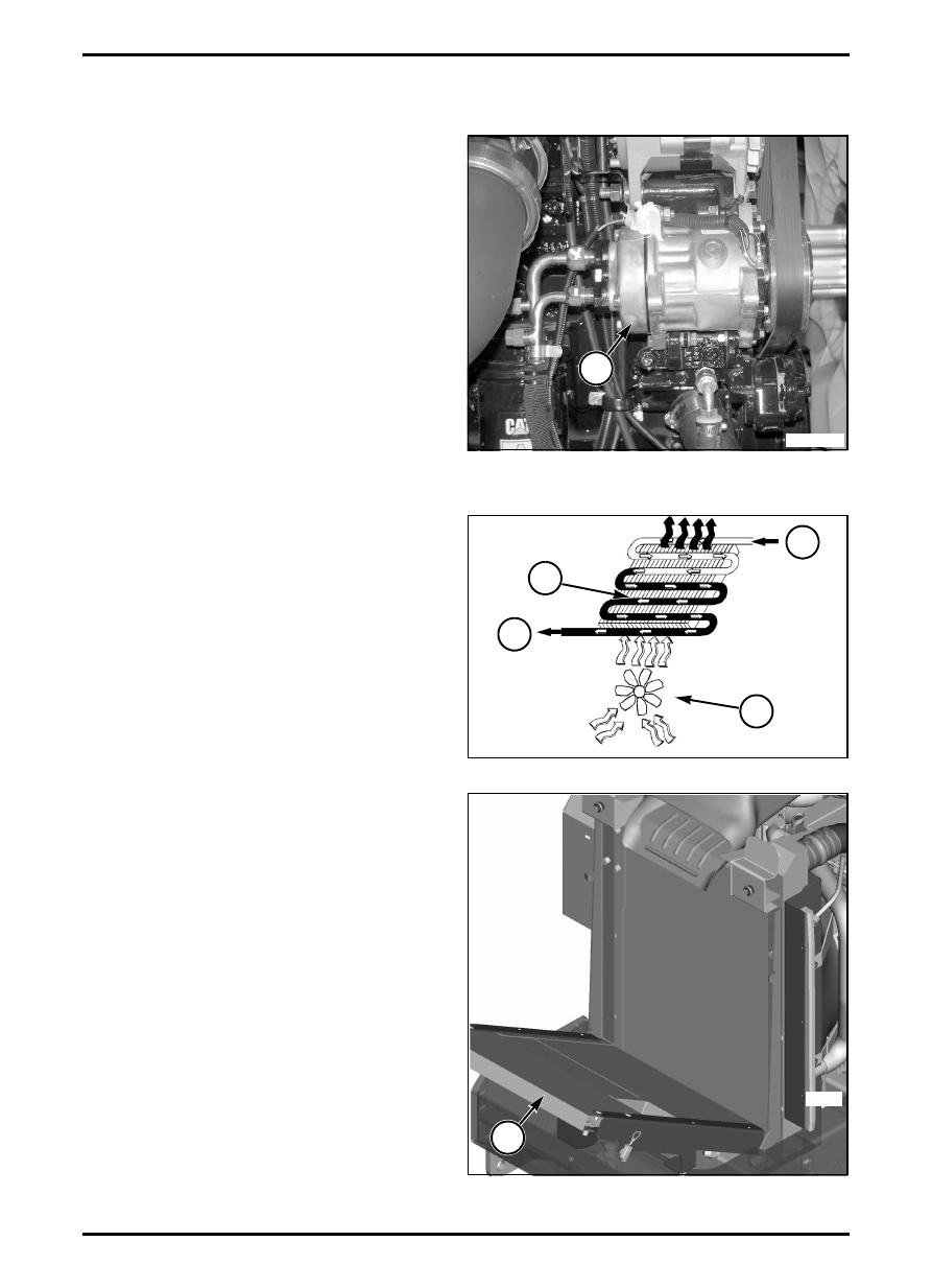
Refrigerant Compressor

FIG. 4: Refrigerant Compressor (1)

Belt-driven and located on engine’s left front, magnetic

clutch is used to engage compressor. Compressor

separates the low and high pressure sides of system

and is basically a pump with two functions:

Raising refrigerant temperature and pressures by

compression.

Functioning as a pump to circulate required volume

of refrigerant and refrigerant oil around system.

See Systems Operation/Testing and Adjusting,

Refrigerant Compressor for additional information.

Refrigerant Condenser

FIG. 5: Condenser Operation

Condenser (1)

Refrigerant from Compressor (2)

Refrigerant to Orifice Tube (3)

Condenser Fan (4)

FIG. 6: Refrigerant Condenser (1)

Located in front of radiator.

Heat is transferred from refrigerant to outside air in

condenser. Transfer is in opposite direction as transfer

in evaporator coil. Fins on outside surface of condenser

are for efficient heat transfer. If refrigerant is not cooled

enough, air inside cab at evaporator coil is not cooled

sufficiently. To prevent this, good ventilation must be

provided. This makes cooling refrigerant more efficient.

Condenser consists of a number of turns of continuous

coil mounted in a series of thin cooling fins to provide

maximum heat transfer in a contained amount of

space.

Condenser receives hot, high-pressure refrigerant

vapor from compressor. The hot vapor passes through

condenser coils. Outside air is pulled through

condenser by engine fan. Heat moves from hot

refrigerant vapor into cooler outside air flowing across

condenser coils and fins.

FIG. 4

M111703002

1

FIG. 5

2

3

1

4

N011803001

FIG. 6

1

M00129

627333-A  

5-17

HVAC

Then refrigerant vapor reaches pressure and

temperature that induces a change of state, a large

quantity of heat is transferred to outside air and

refrigerant changes to a high-pressure cool liquid and

moves to receiver/drier.

See Systems Operation/Testing and Adjusting,

Refrigerant Condenser for additional information.

Receiver/Drier

FIG. 7: Receiver/drier (1) stores liquid refrigerant to

ensure a steady flow to thermostatic expansion valve is

maintained under widely different operating conditions.

Receiver/drier consists of several components:

The drier section contains a desiccant to absorb any

moisture within system and a filter to prevent entry of

foreign particles.

A high-pressure relief valve, mounted on outside of

receiver/drier, provides protection for system in case of

extremely high pressure spikes.

FIG. 7

M110703004

1

HVAC

5-18

627333-A  

A/C and Heating System Schematic

Two sensors monitor refrigerant pressure:

Pressure sensor for side of high pressure

Pressure sensor for side of low pressure

Pressure sensor on side of high pressure ensures

pressure does not go too high or too low. If either

occurs, compressor shuts off to protect system.

Pressure sensor on side of low pressure ensures

pressure does not go too low. If this occurs,

compressor shuts off to protect system.

Compressor Clutch

Clutch Operation

FIG. 8: Components

Magnetic Clutch and Pulley Assembly (1)

Drive Plate (2)

Bearing (3)

Shaft (4)

Coil Assembly (5)

Compressor is driven clockwise by engine. A belt

connects engine to clutch and pulley assembly located

on clutch. Drive plate is fastened to shaft of

compressor. Clutch and pulley assembly turn on a

bearing and is not connected to shaft. Electric current

from thermostat controls a magnetic field in coil

assembly, pulling drive plate against clutch and pulley

assembly, turning shaft and operating compressor.

When current to coil assembly is stopped, magnetic

field is removed allowing drive plate to move away from

clutch and pulley assembly, moving freely on bearing.

Sequence of connecting and disconnecting pulley to

compressor shaft is called compressor cycling and is

controlled by thermostat. Used to monitor temperature

of evaporator coil.

Control for Clutch

See Systems Operation/Testing and Adjusting, Control

Module for more information regarding control of

compressor clutch.

Suction (Suction Side)

Suction lowers refrigerant pressure in evaporator.

Metered restriction, provided by orifice tube, allows

high pressure liquid to be reduced to a low pressure

liquid, helping with evaporation of refrigerant, leading to

continuous cooling.

Pumping

Pumping circulates refrigerant in air conditioning

system, leading to continuous cooling.

FIG. 8

N011803004

5

1

2

4

3

627333-A  

5-19

HVAC

Compression (Discharge Side)

As pressure increases so does temperature of

saturation. Compressor changes refrigerant from a low

to a high pressure vapor. Change must occur for latent

heat of condensation to be produced when refrigerant

is sent through condenser.

Operation of Compressor

FIG. 9: Compressor Operation

Intake Valve (1)

Exhaust Valve (2)

Intake Valve (3)

Exhaust Valve (4)

Intake Stroke (5)

Compression Stroke (6)

Compressor uses reed valves to control entry and exit

of refrigerant gas.

As piston moves down, reed valve opens on suction

side and closes on discharge side. Low pressure

refrigerant gas has weight due to a heat transfer

characteristic and is drawn from evaporator into

compressor. As piston moves up, compressor

pressurizes gas which increases heat.

Since temperature is a measurement of heat intensity,

temperature of gas increases. Gas is high pressure

and temperature. Gas closes reed valve on suction

side and opens on discharge side. Gas is forced

through a hose to condenser.

Pressure increase is accomplished by adding a

restriction in high pressure side of system caused by an

orifice tube.

See Systems Operation/Testing and Adjusting, Orifice

Tube for additional information.

REFRIGERANT RELIEF VALVE

FIG. 10: Relief Valve

Relief valve is located on compressor at high pressure

outlet and protects system by discharging refrigerant

into atmosphere when high pressure reaches a preset

amount to prevent failure.
Body (1)
Packing (2)
Valve (3)
Spring (4)
Relief Valve (5)

TEMPERATURE SENSORS

Temperature sensors are used for automatic

temperature control system: 

Cab airflow temperature

Outside temperature

Ventilation duct temperature

Probe for evaporator core

FIG. 9

N011803006

1

2

3

4

3

1

2

4

5

6

FIG. 10

2

3

4

1

5

N011803007


Content   ..  104  105  106  107   ..