Challenger Terra Gator 3244 Chassis. Manual - part 97
 

  Index      Challenger     Challenger Terra Gator 3244 Chassis - service repair manual 2009 year


Search            


Content   ..  95  96  97  98   ..


Challenger Terra Gator 3244 Chassis. Manual - part 97


Page 27

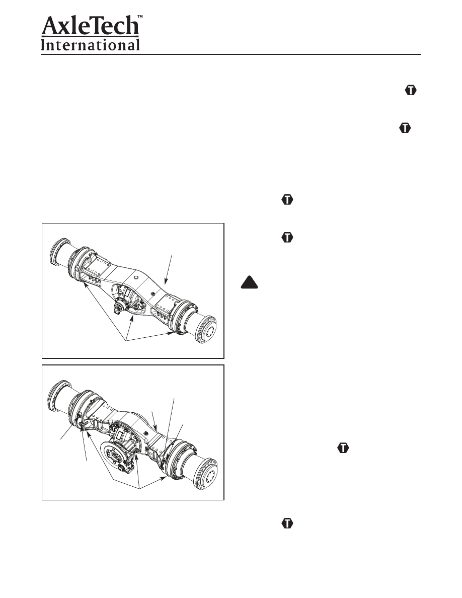
Axle Housing Plugs Assembled 

1. Install the (1.06”) non-magnetic oil fill plug with O-ring

assembly into the upper carrier bowl area of the axle

housing. Tighten per “Torque Table” in section 6.

2. Install the (3) (1.06”) axle magnetic drain plugs with 

O-ring assemblies into the axle housing in the bottom

of the carrier bowl and at the bottom of each axle

flange. Tighten per “Torque Table” in section 6.

3. Install axle breather in the 3/8-18 NPSF port.
If the axle being assembled has the wet brake feature,

need to include the following additional steps:
1. Install the (2) (1.06”) wet brake inspection port non-

magnetic plugs with O-rings assembled, if this axle

has wet brake option. Tighten per “Torque Table” in

section 6.

2. Install the (7/16”) wet brake bleeder on the top of

each axle housing flange, if this axle has the wet

brake option. Tighten per “Torque Table” in 

section 6.

Axle Without Wet Disc Brake
Assembly

CAUTION

Take care when using lifting devices. When 
you use a lifting strap, inspect the strap for 
damage before you use it. Do not use a lifting
strap to shock load or drop load a component.
Serious personal injury and damage to 
components can result.
If the axle being assembled is less wet brake, the 

following assembly procedure is recommended. (All

steps are to be done to each axle housing flange end).

Should the axle be with wet brake, skip to next section.
1. Using lifting straps, rotate the axle housing so the car-

rier is facing forward and secure the axle assembly so

no personal injury or component damage can occur.

2. Apply medium strength thread locker into the (2)

holes that will be used for the M18 studs. Install the

studs at 2:00 and 10:00 positions and tighten per

“Torque Table” in section 6.

3. Add a few drops of medium strength thread locker

into each of the (2) threaded holes in the axle housing

flange for the M8 capscrews to be installed soon.

4. If the axle being assembled is less wet brake, install

the spring housing to axle housing with (2) washers

and (2) M8 capscrews into the threaded holes in the

axle housing flange and tighten per “Torque Table” in

section 6.

!

Section 4

Assembly

Figure 4.4

WET BRAKE
INSPECTION
PORT

WET DISC BRAKE INSPECTION PORT

Trunnion Mount Axle Assembly With Wet Brake

FILL PLUG

MAGNETIC DRAIN PLUG

Figure 4.6

Figure 4.5

FILL PLUG

MAGNETIC DRAIN PLUG

BRAKE
ACTUATION
PORT
FITTING

BRAKE ACTUATION
PORT FITTING

Rigid Mount Axle Assembly Less Wet Brake

Rigid Mount Axle With Park Brake

WET DISC
BRAKE
INSPECTION
PORT

FILL PLUG

WET BRAKE
INSPECTION
PORT

MAGNETIC DRAIN PLUG

3. Assemble the (2) D-Rings on the outer diameter of the

wet brake piston and add a thin coat of oil to the outer

surface of both D-Rings. Care should be taken not to

twist or damage the D-Rings during this assembly.

Also see brake exploded views in front of manual.

Figure 4.9.

4. Add a few drops of medium strength thread locker

into each of the (2) threaded holes in the axle housing

flange for the M8 capscrews to be installed soon.

Page 28

Axle Shaft, Thrust Washer,
Snap Ring, Sun Gear Assembly

Complete this assembly for each axle shaft to be

assembled. Note there are a long and short axle shaft to

be assembled. Figure 4.7.

1. Slide the planetary sun gear on the axle shaft 

planetary splines.

NOTE:

The snap ring should rotate freely in the snap

ring groove, if properly installed. This should be

checked to assure snap ring is seated.
2. Install the snap ring in the snap ring groove of the

axle shaft.

3. Install the thrust washer into the spring housing. 
4. Slide the correct length axle shaft assembly through

the thrust washer, spring housing, into the axle 

housing and engage the carrier side gear splines.

Wet Brake Assembly in the Axle
Housing

CAUTION

Take care when using lifting devices. When 
you use a lifting strap, inspect the strap for 
damage before you use it. Do not use a lifting
strap to shock load or drop load a component.
Serious personal injury and damage to 
components can result.
If the axle has the wet brake being assembled, the 

following procedure is recommended. (All steps are to

be done to each axle housing end).
1. Using lifting straps, rotate the axle housing so the car-

rier is facing forward and secure the axle assembly so

no personal injury or component damage can occur.

2. Install the (6) stationary disc dowels, if were removed

during disassembly, into the half rounds in the axle

housing flange. These dowels will guide the wet brake

stationary disc and backing plate. Figure 4.8.

!

Section 4
Assembly

Figure 4.8

LARGE D RING

SMALL D RING

RETURN SPRING

SPRING GUIDE DOWEL

SPRING HOUSING

FRICTION DISC
ENGAGES SUN GEAR

SUN GEAR

AXLE SHAFT

SNAP RING

BACKING PLATE

STATIONARY DISC
ENGAGES DOWEL

6 DOWELS

THRUST WASHER

Figure 4.9

SPRING DOWEL

SPRING

THRUST
WASHER

SUN GEAR

M8 CAPSCREWS AND WASHERS

SPRING HOUSING

AXLE SHAFT

PISTON

D-RING SEALS

SNAP RING

Figure 4.7

AXLE SHAFT

SUN GEAR

SNAP RING

Page 29

5. Apply a thin coat of oil to the wet brake piston bore

and install the wet brake piston and D-Ring 

assemblies into the axle housing flange bore, 

including the lead-in chamfer area.

6. Place the piston and D-Rings assembly against the

lead chamfer in the piston housing.

7. Oscillate the piston 15-20 degrees easily by hand.

Easy movement indicates good fit and piston is well

centered and seated against the lead chamfer in the

axle housing flange. 

NOTE:

If excess effort is required to manually press the

piston into the axle housing flange, it may mean the pis-

ton is cocking and not being pressed parallel. If cocking

occurs, the piston may bind and scratch the critical seal

surfaces.
8. Install the (4) wet brake spring guide dowels, if were

removed during disassembly, through the piston and

into each axle housing flange bore. 

9. Press the piston by hand into the piston housing of

the axle housing flange.

10. Slide the (4) return springs over the spring guide

dowels.

11. Place the spring housing against the return springs.
12. Install the spring housing to axle housing with the 

(2) M8 capscrews into the threaded holes in the axle

housing flange, compressing the (4) return springs,

and tighten per “Torque Table” in section 6.

Axle Shaft, Thrust Washer,
Snap Ring, Sun Gear Assembly

Complete this assembly for each axle shaft to be

assembled. Note there are a long and short axle shaft to

be assembled. Figure 4.10.

1. Slide the planetary sun gear on the axle shaft 

planetary splines.

NOTE:

The snap ring should rotate freely in the snap

ring groove, if properly installed. This should be

checked to assure snap ring is seated.
2. Install the snap ring in the snap ring groove of the

axle shaft.

3. Install the thrust washer into the spring housing. 
4. Slide the correct length axle shaft assembly through

the thrust washer, spring housing, into the axle 

housing and engage the carrier side gear splines.

Install the Wet Brake Disc
Components into the Axle Housing

Install the wet brake disc components, if this axle has the

wet brake feature, in the reverse sequence of the order

that they were removed and set aside for reassembly.
1. Use rubbing alcohol to clean the surface of the

shim prior applying adhesive and apply #Q58

adhesive to the shim that mounts to the axle housing

face and align the hole pattern as attach the shim to

the axle housing flange surface. Figure 4.11.

If assembly has one friction disc, refer to Figure 4.12

for sequence of discs.

2. Install a stationary disc against the piston into the

axle housing flange aligning the slots in the disc

with the (6) axle housing flange dowels.

3. Install the friction disc on the planetary sun gear

aligning the splines.

NOTE:

The backing plate’s step surface is to be

installed away from the friction disc towards the wheel

end planetary assembly.

Section 4

Assembly

Figure 4.12

STATIONARY
DISC

FRICTION DISC

BACKING PLATE’S
STEP SURFACE

DOWEL

WHEEL END ASSEMBLY

Figure 4.11

SHIM

DOWEL

Figure 4.10

AXLE SHAFT

SUN GEAR

SNAP RING

Page 30

4. Install the backing plate with flat surface toward

friction disc, into the axle housing flange, aligning

the slots in the plate with the (6) dowels.

If assembly has two friction discs, refer to Figure 4.13

for sequence of discs.

2. Install a stationary disc against the piston into the

axle housing flange aligning the slots in the disc

with the (6) axle housing flange dowels.

3. Install the friction disc on the planetary sun gear

aligning the splines.

4. Install (2) more stationary discs against the first

friction disc, aligning the slots with the (6) axle

housing flange dowels.

5. Install the second friction disc on the planetary sun

gear aligning the splines.

6. Install the backing plate into the axle housing

flange with flat surface toward friction disc, aligning

the slots in the plate with the (6) dowels.

Wet Disc Brake Actuation and
Functional Test

1. Install a fixture or the planetary ring gear against

the shim to limit piston travel.

2. Bolt this fixture into the tapped M18 holes in the

axle housing flange by using (3) M18 capscrews

with washers stacked as necessary under cap-

screw heads.

3. Install a pressure gauge into the inlet port for accu-

rately measuring 690kPa (6.9 Bar, 100 psi).

4. Connect hydraulic pressure line with a shut off

valve using a maximum hydraulic pressure of

690kPa (6.9 Bar, 100 psi) actuation pressure.

5. Actuate the piston 5 times to 690kPa (6.9 Bar, 

100 psi) checking that the piston extends freely

and returns to starting position when hydraulic

pressure is released. 

6. Actuate piston again, lock in pressure and hold at

maximum 690kPa (6.9 Bar, 100 psi). The gauge

should read a limit 34kPa (0.34 Bar, 50 psi) 

maximum drop after 1 minute.

7. Should the assembly not pass this test, The piston

should be removed and D-Rings inspected and the

axle housing bores checked for surface scratches,

repaired and re-assembled and the test procedure

rerun, until passing test.

Spindle and Planetary Ring Gear
Sub-Assembly

The planetary ring gear assembles between the spindle

and axle housing. The ring gear can first be reassem-

bled onto the axle housing or onto the spindle. In either

case, the final assembly requires O-rings installed in the

grooves on both sides of the ring gear. If the planetary

ring gear was disassembled from the spindle earlier, the

following (2) assembly procedures are recommended to

reassemble the ring gear and spindle. Figure 4.14.

If this method is selected for assembly,

CAUTION

Care should be taken not to press directly on the
spindle threads as damage to these threads may
occur. Use of 3 steel bars assembled to allow the
press to push on the spindle flange directly and
not on the spindle threads is recommended.
1. Apply light coat of grease to the O-Ring.
2. Install the O-Ring into the groove on the planetary 

ring gear face. Care should be taken not to twist or

damage the O-Ring during assembly.

3. Align the capscrew holes in the ring gear when you

are pressing the ring gear into the spindle. The hole

alignment must be done prior actually pressing ring

gear into spindle.

!

Section 4
Assembly

4.14

O-RING

RING GEAR

SPINDLE

INSTALL BOLTS, NUTS AND WASHERS, FOR SAFETY

Figure 4.13

STATIONARY DISC

FRICTION DISC

BACKING PLATE
STEP SURFACE

WHEEL END ASSEMBLY

DOWEL


Content   ..  95  96  97  98   ..