Challenger Terra Gator 3244 Chassis. Manual - part 95
 

  Index      Challenger     Challenger Terra Gator 3244 Chassis - service repair manual 2009 year


Search            


Content   ..  93  94  95  96   ..


Challenger Terra Gator 3244 Chassis. Manual - part 95


Page 19

CAUTION

Damage to bearings can result when they are
rotated and dried with compressed air.
3. Except for bearings, parts can be dried with 

compressed air.

Prevent Corrosion On Cleaned
Parts

1. Apply axle lubricant to cleaned and dried parts 

that are not damaged and are to be re-assembled.

2. To store parts, apply a special material that 

prevents corrosion to all surfaces. Wrap cleaned

parts in a special paper that will protect the parts

from moisture and prevent corrosion.

Inspect Parts

Tapered Bearing

It is very important to inspect all parts carefully and

completely before the axle assembly is assembled.

Check all parts for wear and replace damaged parts.

Replacement of damaged or worn parts will prevent

breakdown of assembly later. Inspect the cup, cone,

rollers and cage of all tapered roller bearings in the

assembly. If any of the following conditions exist,

replace the bearing.

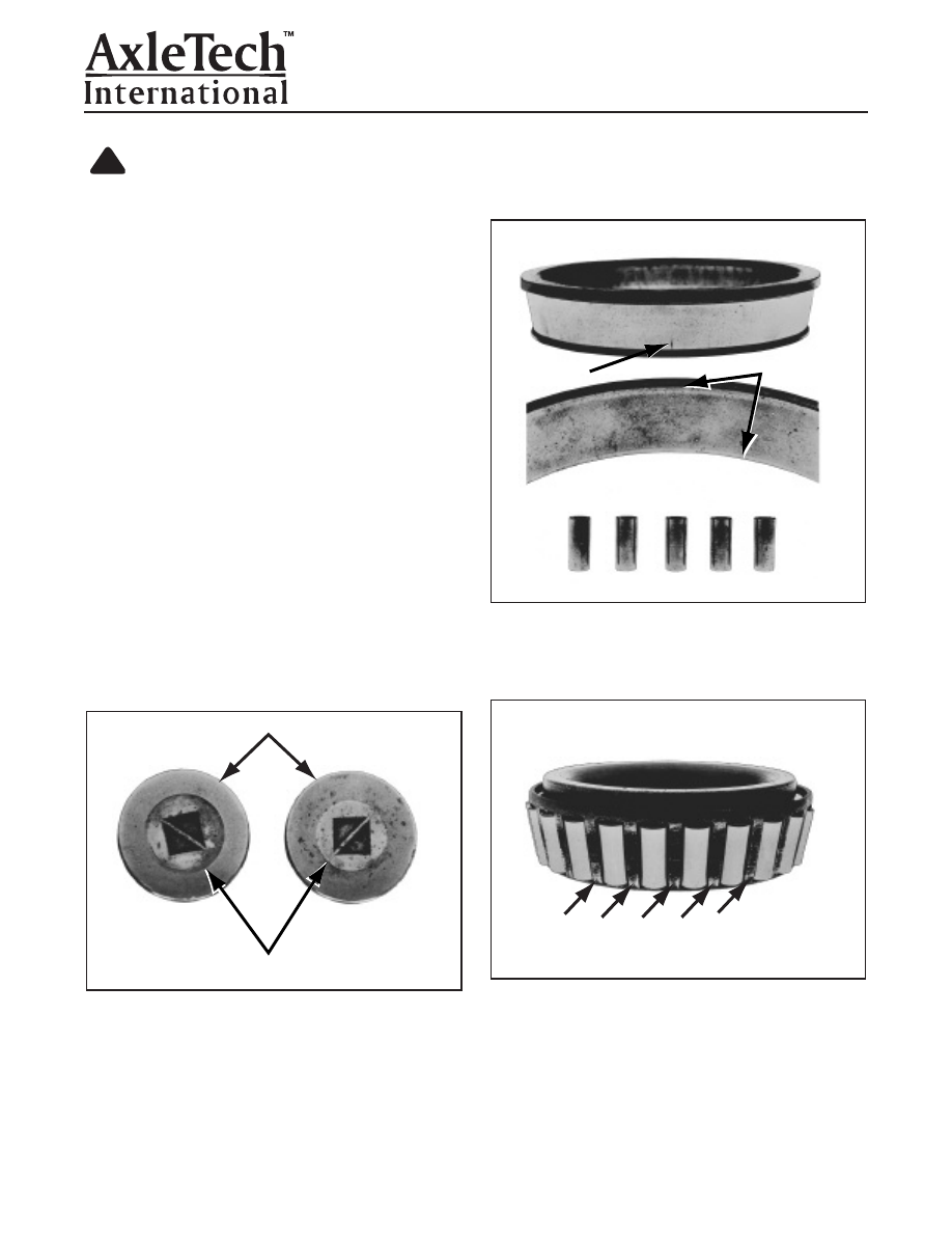
• The large-diameter end of the rollers is worn level

with or below the center surface. Figure 3.1.

• The radius at the large-diameter end of the rollers

is worn to a sharp edge. Figure 3.1.

!

• There is a visible roller groove in the cup or cone

inner race surfaces. The groove can be seen at

the small- or large-diameter end of both parts.

Figure 3.2.

• There are deep cracks or breaks in the cup, cone

inner race or roller surfaces. Figure 3.2.

• There are bright wear marks on the outer surface

of the roller cage. Figure 3.3.

1003017a

WORN SURFACE

WORN RADIUS

Figure 3.1

1003018a

WEAR GROOVES

CRACK

Figure 3.2

1003019a

WEAR MARKS

Figure 3.3

Section 3

Prepare Parts for Assembly

Page 20

• There is damage on the rollers and on the 

surfaces of the cup and cone inner race that 

touch the rollers. Figure 3.4.

• There is damage on the cup and cone inner race

surfaces that touch the rollers. Figure 3.5.

There is any sign of cracks or damage to the 

roller cage assembly that retain the individual 

taper rollers.

Planetary Wheel End Gearing

CAUTION

The planetary sun gear, planetary gears and ring
gear work together similar to a matched set.
Damage to the sun gear or planet gears can also
damage the planetary ring gear. It is strongly 
recommended that when any noted damage to
any of these gears might occur, the complete set
in a planetary wheel end should be changed.
• All gears should be inspected for cracks, chipping 

of the teeth, scoring, pitch line damage, or heavy

teeth wear.

• The planetary pinion gears should also be checked

for any signs of wear or smoothness damage to the

pinion gear bores.  

!

• The planetary ring gear should be checked for signs

of heavy wear, teeth chipping or scoring or deep

scratches around the O-ring groove diameters.

• The planetary sun gear should be checked for any

signs of wear on the gear teeth, scoring, chipping of

gear teeth, signs of wear or burrs on the wet brake

splines on the sun gear, and internal spline wear,

burrs, or other spline damage. Figure 3.6.

CAUTION

The planetary pinion shafts are not serviceable
items and must not be pressed out of the 
planetary spider shaft. Also take care to maintain
the matched set markings on planet pinion shafts
during cleaning process.

Needle Roller Bearings

CAUTION

Any damage to these rollers can damage the
planetary pinion shaft or pinion gear bore. The
needle rollers should also be inspected for end
wear on the individual needle rollers.
All the planetary pinion gears have a “full complement”

of needle roller bearings. Keep (33) needle roller 

bearings grouped with their planet gear. These needle

rollers should be inspected for roughness, pitting, or

any signs of wear to the individual roller outer 

diameter surface. 

Planetary Wheel End Thrust
Washers

WARNING

Any wear will cause metallic debris and early
component failures.
The planetary thrust washers should be examined 

for any signs of wear on the flat thrust surfaces from

either the needle rollers or the planetary pinions 

rubbing against this surface. 

!

!

!

1003020a

ETCHING AND PITTING

Figure 3.4

1003021a

SPALLING AND FLAKING

Figure 3.5

Section 3
Prepare Parts for Assembly

Figure 3.6

SNAP RING

INNER THRUST
WASHER

PLANETARY
PINION GEAR

ROLLERS

OUTER THRUST
WASHER

PLANETARY
PINION SHAFT

PLANETARY SPIDER

Page 21

Planetary Spider Shaft

Inspect the planetary spider shaft for any signs of

wear, burrs, scratches or other damage to the 

planetary pinion shafts. Inspect the splines where the 

driver is mounted for signs of wear and the snap ring

groove for wear or burrs. 

Wheel End Spindle

Inspect the planetary spindle for any damage or

scratches to the bearing journals. The face seal bore

should be inspected to review for scratches to the

seal bore. Light clean up is allowed with emery cloth,

fine file, India stone, or crocus cloth. The spindle bore

and threads should be checked for wear or any 

damage for the nut locking system. The spindle

should also be reviewed in the lock plate mating tang

interfaces for any burrs, signs of damage or wear.

The spindle thread for the wheel bearing adjusting nut

should be reviewed for any damage to the threads

that will not allow the spindle adjusting nut to assem-

ble. Minor repair is allowed to this thread by using a

metric thread die or file to repair a damaged thread.

Driver

The driver should be inspected for any signs of wear,

burrs, or damage to the internal splines that attach 

to the planetary spider shaft. Burrs may be removed

by use of a light file. Look for any rubbing marks 

indicating contact with end of spindle. Any 

interference should be removed by grinding 

spindle’s tapered inside diameter. 

Planetary Nut Lock System

Inspect the wheel bearing adjusting nut, lock plate,

and capscrews for any signs of wear or damage. The

capscrew thread should have the previously applied

thread-locker removed during cleaning, prior inspec-

tion. The capscrews should be replaced if any 

damage is noted on the threads. Inspect the tangs 

on the lock plate for any signs of wear or damage to

the lock plate capscrew holes.

Planetary Assembly O-Rings

Inspect each O-Ring for any signs of wear, being torn,

pinched, cut, nicked, or swelling. Replace if damage

is noted.

Axle Shafts

Inspect axle shafts for wear and cracks at the shaft

and splines. Replace the axle shafts, if required.

Inspect axle shaft snap ring groove for burrs. Clean

up is permitted by using a light file.

Axle Housing

Inspect the axle housing for any signs of cracks, or

damage from service usage, or stripped threaded

holes. 

WARNING

Repair of axle housings by bending or straighten-
ing can cause poor or unsafe vehicle operation
and axle failure. Any axle housing bending or
straightening is Not allowed. Serious personal
injury and damage to components can result.
The housing material for PRC2715, PRC2725,

PRC2726, PROC2715 and PROC2725 axle families

is not suitable for welding. Do not attempt to repair

weld a drive axle. All threads should be cleaned 

to remove previously applied thread-locker for 

later reassembly.

Axle Trunnion Components

Inspection of both trunnion bracket assemblies 

follows the same inspection procedures.  
1. Inspect each trunnion bracket for any signs of 

wear or scratches to the inner bore surface. Light

scratches may be repaired with emery cloth, 

India stone, or crocus cloth.

2. Inspect each bushing for signs of wear or light

scratches on both the inner and outer diameter 

surfaces. Light scratches may be repaired with

emery cloth, India stone, or crocus cloth.

3. Inspect each grease seal assembly for nicks, cuts,

torn material, or scratches on the seal lip material,

or any evidence that the seal lips are damaged or

worn. Inspect the seal assembly to check the

spring is not damaged and functions properly.

Inspect the seal guard for damage due to field

usage or disassembly. Should the grease seal

show any evidence that dirt or other contamination

has passed the seal lips, these seals should be

changed for new seal assemblies. 

4. Inspect the trunnion adapter and trunnion shaft

components for light scratches to the bore and

journal surfaces. Light scratches may be repaired

with emery cloth, India stone, or crocus cloth.

5. Inspect the thrust washers for any burrs, scratches,

or wear to the flat faces.  Light scratches may be

repaired with a fine file, emery cloth, India stone, or

crocus cloth.

6. Inspect all capscrews and brush to remove 

previously applied thread locker and check to

assure the threads are not damaged and the 

capscrew heads are not worn.

Wet Brake Assembly Components

Inspect the wet brake components per the following

recommended procedures:
1. Inspect the friction and stationary brake discs for

flatness and wear. The friction disc lining should be

inspected to check for unusual wear. Measure the

thickness of the discs. Overall thickness should not

!

Section 3

Prepare Parts for Assembly

Page 22

be less than that shown in Table 1. Replace the

entire disc pack if one disc needs replacing.

Table 1.

2. The splines on the friction disc should be reviewed

for wear or cracks evident on the spline teeth. The

backing plate and stationary disc should be

inspected for scratches on the mating surface to

the friction disc. Scratches may be removed with

emery cloth, India stone, or crocus cloth. The tangs

on the stationary disc(s) should be inspected for

wear.

3. Inspect the backing plate for scratches on mating

surfaces to the friction plate. Scratches may be

removed with emery cloth, India stone, or crocus

cloth. The tangs should be inspected for wear.

4. Inspect the wet brake piston for any signs of wear

or light scratches. The piston's 2 seal grooves

need to be inspected for any wear or burrs. Burrs

and light scratches may be removed with emery

cloth, India stone, or crocus cloth. Inspect the

housing’s piston bores for wear or rough spots.

Polish out rough spots with fine crocus cloth.

5. Inspect the D-Ring seals for nicks, cuts, torn 

material, swelling, or evidence that the seal is 

damaged or worn. If any damage is noted, these

D-Ring seals should be replaced with new 

components.

6. Inspect the wet brake piston return springs and

dowels for damage or wear. Scratches on the 

dowels, may be removed with emery cloth, India

stone, or crocus cloth.

7. Inspect any wet brake hydraulic tubing assemblies

and the fittings for any signs of damage to the

tubes, hydraulic nut faces, or fitting threads.

Replacement with new components is required 

if any damaged is noted.

8. Inspect TRS Toric Ring face seals as follows:

CAUTION

Install face seal halves in the same positions
where they were located prior to disassembly.
Mixing up face seal halves can cause component
damage.

Look for obvious signs of damage. Replace any

damaged face seal or O-ring. Replace any 

O-ring that is stuck to the seal or brake housing or

any that has taken a “set” or cannot be pulled and

“snapped” into position on the seal ring retaining lip. 

!

Toric Ring formed face seals are more flexible than

cast ring seals and, as a result, produce a wear

pattern different than cast ring designs. Typically,

formed seals wear in an axial rather than radial

direction, as depicted below, due to their increased

flexibility. Figure 3.7.

The total thickness of the flange is the usable wear

material on the formed seal rings, and good seal

performance can generally be expected until the

flange is completely worn away. Estimate the

remaining service life of the seal ring by measuring

the ring flange thickness and comparing that meas-

urement to those listed in Table 2. The minimum

flange thickness required for seal ring usability is

1.27 mm (0.050 in.). 

With formed seal rings, the measured parameter

used to check the remaining seal ring life is the

flange thickness at the outer edge. Measure care-

fully, since the shoulder is only 1.52 mm (0.060 in.)

from the edge of the flange. 

*Seal ring not usable. Replace seal ring.

Section 3
Prepare Parts for Assembly

Minimum Brake Disc Thickness
Disc Type 

Part Number

Minimum Thickness

Friction

A3281L1260 0.192 Inch (4.87 mm)

Stationary

3281M1261

0.167 Inch (4.24 mm)

Flange Thickness

Seal Wear

mm (inch)

% Worn

1.91 (0.075)

0

1.59 (0.062)

25

1.27 (0.050)

50

0.95 (0.038)*

75

0.64 (0.025)*

100

0.32 (0.012)*

125

0.00 (0.000)*

150

Table 2. Formed Seal Wear Chart

Figure 3.7

LOCATION OF WEAR LIP WHICH
MUST BE REMOVED

DEVELOPMENT OF A WEAR LIP IN
THIS AREA MAKES IT NECESSARY
TO INSTALL A NEW SEAL


Content   ..  93  94  95  96   ..