Challenger Terra Gator 3244 Chassis. Manual - part 47
 

  Index      Challenger     Challenger Terra Gator 3244 Chassis - service repair manual 2009 year


Search            


Content   ..  45  46  47  48   ..


Challenger Terra Gator 3244 Chassis. Manual - part 47


40

KENR6054

Disassembly and Assembly Section

g01280780

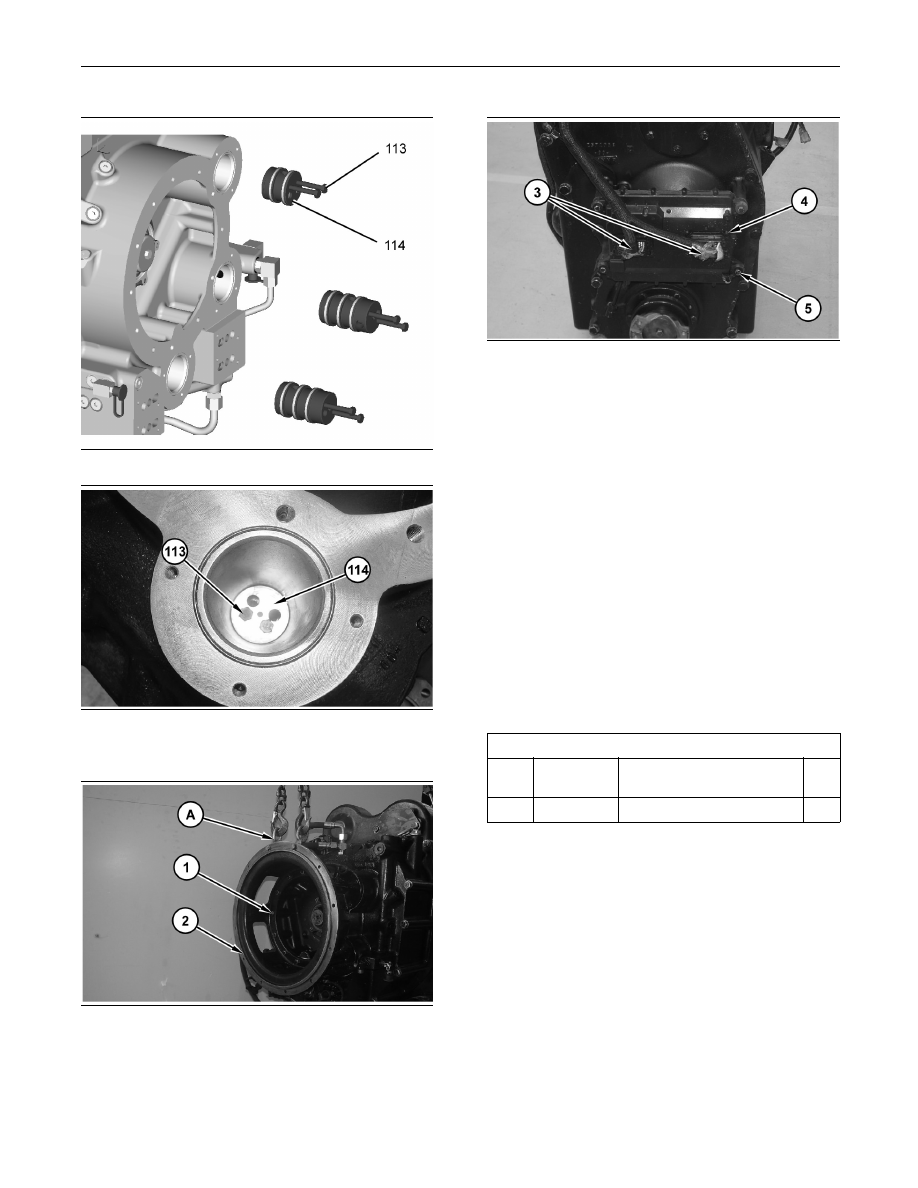
Illustration 156

g01279344

Illustration 157

50. Install seal carriers (114) and install bolts (113).

g01269011

Illustration 158

51. Install the O-ring seals. Use Tooling (A) and a

suitable lifting device in order to install housing

(2). The weight of housing (2) is approximately

35 kg (75 lb). Install bolts (1).

g01269023

Illustration 159

52. Install electronic control module (4) and bolts (5).

Connect harness assemblies (3).

End By:

a. Install the input speed sensor. Refer to

Disassembly and Assembly, “Speed Sensor

(Transmission) - Install”.

i02649518

Clutch (Front Wheel Assist) -

Remove

SMCS Code: 3053-011-OJ; 3054-011-OJ;

3055-011-OJ

Removal Procedure

Table 7

Required Tools

Tool

Part

Number

Part Description

Qty

A

138-7575

Link Brackets

2

Start By:

a. Remove the speed sensor for the front wheel

assist. Refer to Disassembly and Assembly,

“Speed Sensor for the Front Wheel Assist

(Transmission) - Remove”.

KENR6054

41

Disassembly and Assembly Section

NOTICE

Care must be taken to ensure that fluids are contained

during performance of inspection, maintenance, test-

ing, adjusting and repair of the product. Be prepared to

collect the fluid with suitable containers before open-

ing any compartment or disassembling any compo-

nent containing fluids.

Refer to Special Publication, NENG2500, “Caterpillar

Dealer Service Tool Catalog” for tools and supplies

suitable to collect and contain fluids on Caterpillar

products.

Dispose of all fluids according to local regulations and

mandates.

1. Remove the guard.

g01267705

Illustration 160

2. Remove tube assemblies (4). Disconnect harness

assembly (1). Remove bolts (3) and modulating

control valve (2).

g01267706

Illustration 161

3. Attach Tooling (A) and a suitable lifting device to

clutch assembly (5). The weight of clutch assembly

(5) is approximately 70 kg (150 lb). Remove bolts

(6) and clutch assembly (5). Remove O-ring (7).

i02649529

Clutch (Front Wheel Assist) -

Disassemble

SMCS Code: 3053-015-OJ; 3054-015-OJ;

3055-015-OJ

Disassembly Procedure

Table 8

Required Tools

Tool

Part

Number

Part Description

Qty

A

207-8153

Spring Compressor

1

B

2P-8312

Retaining Ring Pliers

1

C

1P-0510

Driver Gp

1

D

8H-0663

Bearing Puller Gp

1

Start By:

a. Remove the clutch (front wheel assist). Refer to

Disassembly and Assembly, “Clutch (Front Wheel

Assist) - Remove”.

g01267904

Illustration 162

1. Remove bolts (1). Remove modulating control

valve (2) and O-ring seal (3).

g01267919

Illustration 163

42

KENR6054

Disassembly and Assembly Section

2. Remove bolts (5) and shroud assembly (4).

g01267925

Illustration 164

3. Remove retaining ring (6). Remove coupling (7)

and clutch assembly (8).

g01267926

Illustration 165

g01267927

Illustration 166

4. Remove plates (9) and discs (10) from coupling

(7).

g01267928

Illustration 167

5. Remove retaining ring (11) from coupling (7).

g01267931

Illustration 168

g01267934

Illustration 169

KENR6054

43

Disassembly and Assembly Section

Personal injury can result from being struck by

parts propelled by a released spring force.

Make sure to wear all necessary protective equip-

ment.

Follow the recommended procedure and use all

recommended tooling to release the spring force.

6. Use Tooling (A) and a suitable press in order to

compress spring (14). Use Tooling (B) in order to

remove retaining ring (12). Remove retainer (13),

spring (14), and sleeve (15).

g01267940

Illustration 170

7. Remove piston (16).

g01267941

Illustration 171

8. Remove seals (17).

g01267948

Illustration 172

9. Remove bolt (19), yoke assembly (18), shims

(20), the retainer, the spacer, and the O-ring seal.

g01267971

Illustration 173

10. Use Tooling (C) and a suitable press in order

to separate shaft assembly (21) from housing

assembly (22).

Note: Support shaft assembly (21) from the bottom.

g01267980

Illustration 174

11. Remove seal rings (23).


Content   ..  45  46  47  48   ..