Challenger Terra Gator 3244 Chassis. Manual - part 45
 

  Index      Challenger     Challenger Terra Gator 3244 Chassis - service repair manual 2009 year


Search            


Content   ..  43  44  45  46   ..


Challenger Terra Gator 3244 Chassis. Manual - part 45


32

KENR6054

Disassembly and Assembly Section

g01269976

Illustration 120

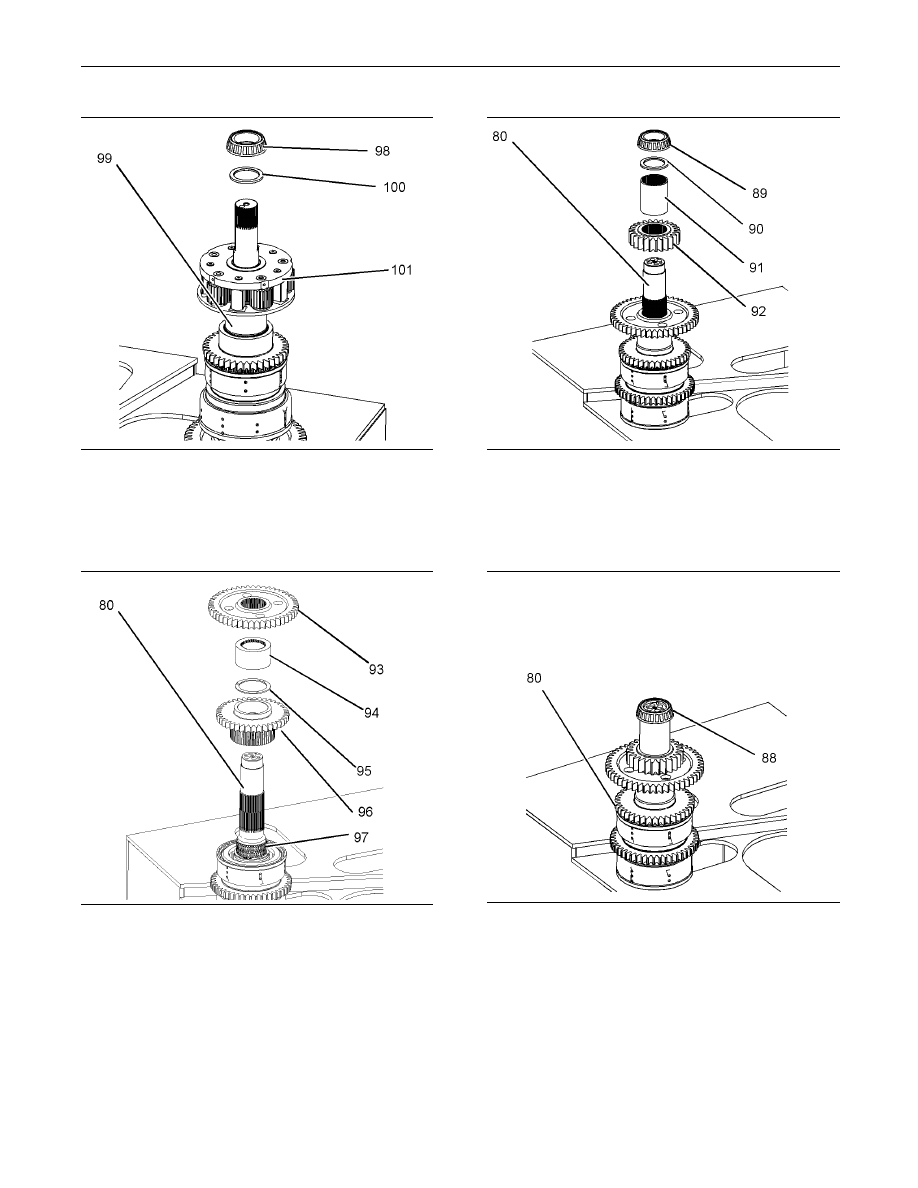
13. Install planetary carrier (101) and spacer (100)

onto shaft assembly (99). Raise the temperature

of bearing cone (98). Install bearing cone (98)

onto shaft assembly (99).

g01269969

Illustration 121
Intermediate Shaft

14. Install bearing (97) onto shaft assembly (80).

Install gear (96), thrust washer (95), spacer (94),

and gear (93) onto shaft assembly (80).

g01269968

Illustration 122

15. Install gear (92), spacer (91), and spacer (90)

onto shaft assembly (80). Raise the temperature

of bearing cone (89). Install bearing cone (89)

onto shaft assembly (80).

g01280589

Illustration 123

16. Raise the temperature of bearing cone (88).

Install bearing cone (88) onto shaft assembly (80).

KENR6054

33

Disassembly and Assembly Section

g01270211

Illustration 124

17. Install thrust washer (83) onto shaft assembly

(80). Install bearing (85) onto shaft assembly

(80). Install gear (84), thrust washer (83), spacer

(82), and spacer (81) onto shaft assembly (80).

Raise the temperature of bearing cone (79). Install

bearing cone (79) onto shaft assembly (80).

g01270206

Illustration 125

18. Install seal (78) onto piston (77). Install seals

(76) onto piston (77). Install piston (77) onto shaft

assembly (55).

g01269765

Illustration 126

g01269767

Illustration 127

Improper assembly of parts that are spring loaded

can cause bodily injury.

To prevent possible injury, follow the established

assembly procedure and wear protective equip-

ment.

19. Use Tooling (J) in order to install spring (75).

Install seal assembly (74) and spacer (73) onto

shaft assembly (55). Use Tooling (H) in order to

install retaining ring (71).

34

KENR6054

Disassembly and Assembly Section

g01269758

Illustration 128

20. Install the friction discs and plates (70) onto shaft

(55). Install clutch plate (69). Use Tooling (H) in

order to install retaining ring (68). Install thrust

washer (67) and bearings (66).

g01269751

Illustration 129
Reverse Shaft

21. Install gear (65) and thrust washer (64). Install

spacer (63). Raise the temperature of bearing

cone (62). Install bearing cone (62).

g01269685

Illustration 130

22. Install spacer (59), gear (58), spacer (57), and

spacer (56) onto shaft assembly (55). Raise the

temperature of bearing cone (54). Install bearing

cone (54) onto shaft assembly (55).

g01281829

Illustration 131

23. Attach Tooling (E) and a suitable lifting device

to shaft assemblies (52). The weight of shaft

assemblies (52) is approximately 370 kg (820 lb).

Install shaft assemblies (52).

KENR6054

35

Disassembly and Assembly Section

g01269438

Illustration 132

g01269440

Illustration 133

Improper assembly of parts that are spring loaded

can cause bodily injury.

To prevent possible injury, follow the established

assembly procedure and wear protective equip-

ment.

24. Install seals (47) and (49) onto piston (48).

25. Install dowels (50) onto housing (51), if necessary.

Install springs (46) and dowels (45). Install plates

(44) and discs (43).

g01269435

Illustration 134

26. Install ring gear (42) and reaction plate (41).

Install bolts (40).

g01269430

Illustration 135

27. Install O-ring seals (39) onto clutch assembly

(38).


Content   ..  43  44  45  46   ..