HUAWEI OptiX OSN 8800 T64/T32 Intelligent Optical Transport Platform. Product Description - part 19
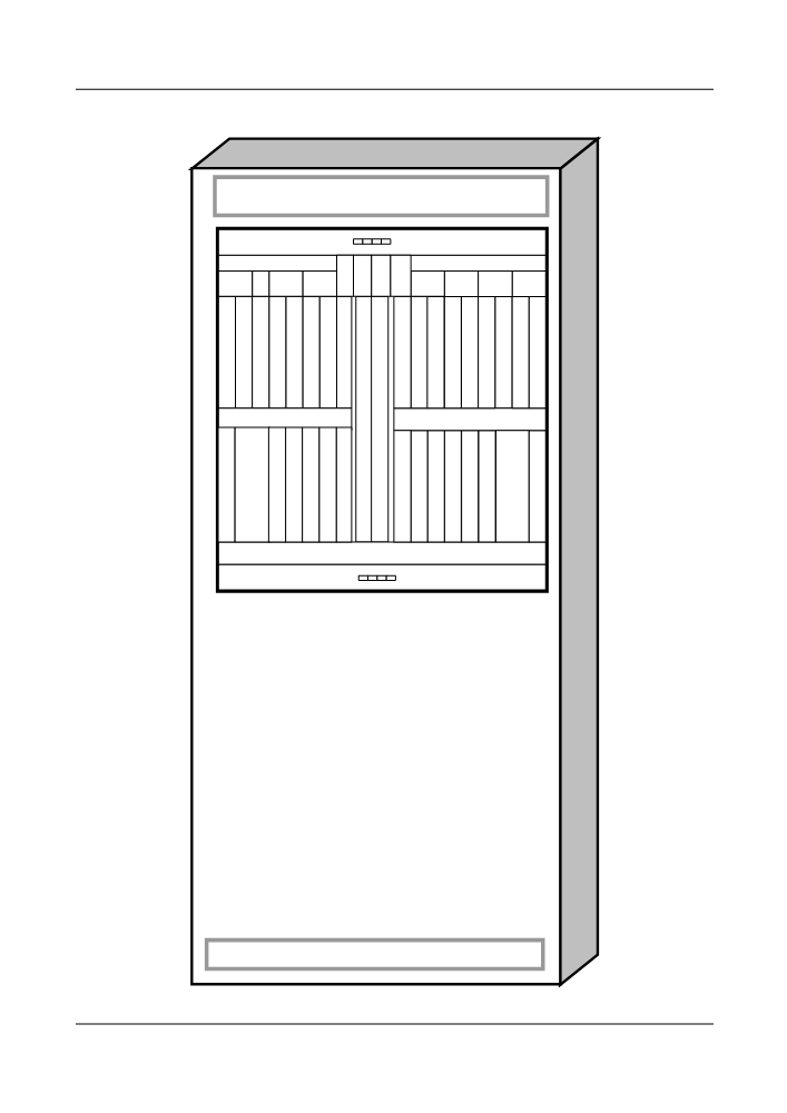
Figure 6-6 Typical configuration of the OLA equipment
FAN
A
S
S
EF
U
T
T
EFI2
PIU
PIU
PIU
PIU
STI
ATE
I1
X
G
G
S
C
C
O
O
F
S
F
A
A
I
C
I
U
U
U
2
U
1
1
FAN
191
6.3 FOADM in a DWDM System
The OptiX OSN 8800 provides FOADM equipment.
6.3.1 FOADM Node with Optical Multiplexer Unit and Optical
Demultiplexer Unit
Functions
FOADM adds/drops fixed wavelengths to/from the multiplexed signals. This FOADM node
type is usually applied to central sites. It consists of two back-to-back OTMs. Its advantage is
that it can be expanded without interrupting the services.
Functional Units
An FOADM consists of:
l Optical transponder unit (OTU)
l Optical amplifier unit (OA)
l Optical multiplexer unit (OM)
l Optical demultiplexer unit (OD)
l Bidirectional optical supervisory channel unit (SC2)
l Fiber interface unit (FIU)
l System control and communication unit (SCC)
For the boards used in each unit, see 4.2 Hardware Architecture.
Signal Flow
The DWDM FOADM node is responsible for processing the optical signals in two transmission
directions.
It separates the optical supervisory signal from the main path optical signals and sends the former
to the OSC unit for processing.
Main path signals are sent into the OADM demultiplexer after amplification. Certain
wavelengths are dropped and enter the OTU before being sent to the local client equipment. The
other wavelengths are not demultiplexed locally. They pass through and are multiplexed with
the locally added wavelengths by the multiplexer before the optical amplification. Finally, the
signals are multiplexed with the processed optical supervisory signals for line transmission.
When the optical transmission distance is long, it may prevent the line extension by one or more
than one affecting factors of system transmission performance, such as dispersion, power, optical
noise, non-linear effect, or polarization mode dispersion. In this case, regeneration OTU can be
configured to perform the 3R (reshaping, retiming, and regenerating) of electrical signals.
The schematic diagram of this FOADM node type is shown in Figure 6-7.
192
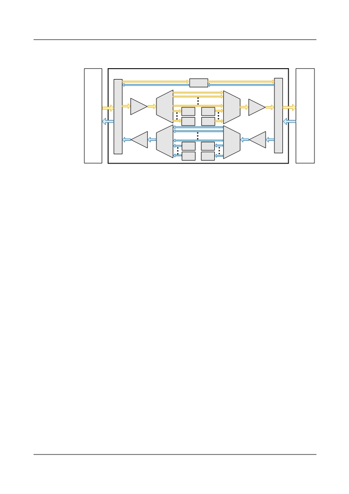
Figure 6-7 Schematic diagram of DWDM FOADM node with the optical multiplexer unit and
the optical demultiplexer unit
SC2
West
East
OA
OD
OM
OA
line-side
OTU
OTU
line-side
ODF
FIU
FIU
ODF
OTU
OTU
OA
OM
OA
OD
OTU
OTU
OTU
OTU
OTU: optical transponder unit
OM: optical multiplexer unit
SC2: bidirectional OSC unit
OD: optical demultiplexer unit
FIU: fiber interface unit
OA: optical amplifier unit
ODF: Optical distribution frame
Typical Configuration
Figure 6-8 uses two-dimensional FOADM equipment (40-channel) formed by the optical
multiplexer M40 and optical demultiplexer D40 as an example of a typical configuration. One
cabinet and two subracks are used.
193
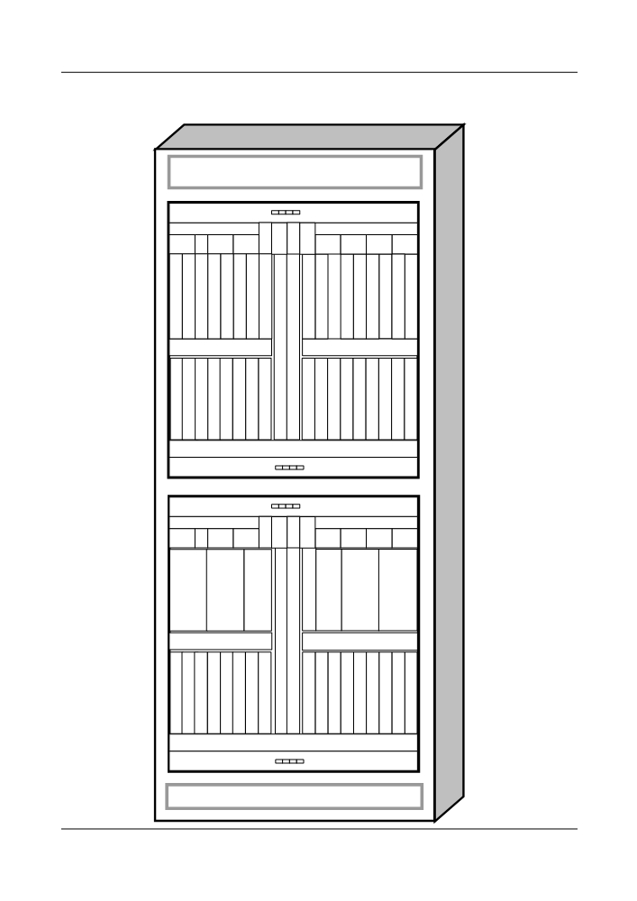
Figure 6-8 Typical configuration of the FOADM equipment that consists of the M40 and the
D40
FAN
A
S
S
EF
U
T
T
EFI2
PIU
PIU
PIU
PIU
STI
ATE
I1
X
G
G
N
N
N
N
N
N
N
N
S
N
N
N
N
N
N
N
N
Q
Q
Q
Q
Q
Q
Q
Q
C
Q
Q
Q
Q
Q
Q
Q
Q
2
2
2
2
2
2
2
2
C
2
2
2
2
2
2
2
2
X
X
C
C
H
H
/
/
X
X
C
C
M
M
T
T
T
T
T
T
T
T
S
Q
Q
Q
Q
O
O
O
O
C
X
X
X
X
M
M
M
M
C
FAN
FAN
A
S
S
EF
U
T
T
EFI2
PIU
PIU
PIU
PIU
STI
ATE
I1
X
G
G
O
O
S
A
A
M40
D40
C
D40
M40
U
U
1
C
1
O
O
F
B
S
S
B
F
I
U
C
C
U
I
U
2
C
U
1
1
FAN
194
6.3.2 FOADM Node with OADM Units
Functions
FOADM adds/drops fixed wavelengths to/from the multiplexed signals. This FOADM node
type is usually applied to edge sites. It has the following features:
l Small insertion loss
l Flexible expansibility
l Low initial investment
Functional Units
An FOADM consists of:
l Optical transponder unit (OTU)
l Optical amplifier unit (OA)
l Optical add/drop multiplexer (OADM)
l Bidirectional optical supervisory channel unit (SC2)
l Fiber interface unit (FIU)
l System control and communication unit (SCC)
For the boards used in each unit, see 4.2 Hardware Architecture.
Signal Flow
The DWDM FOADM node is responsible for processing the optical signals in two transmission
directions.
The FIU separates the optical supervisory signal from the main path optical signals and sends
the former to the OSC unit for processing.
Main path signals are sent into the OADM demultiplexer after amplification. Certain
wavelengths are dropped and enter the OTU before being sent to the local client equipment. The
other wavelengths are not demultiplexed locally. They pass through and are multiplexed with
the locally added wavelengths by the multiplexer before the optical amplification. Finally, the
signals are multiplexed with the processed optical supervisory signals for line transmission.
This type of FOADM node does not support the C-ODD band.
The schematic diagram of this FOADM node type is shown in Figure 6-9.
195
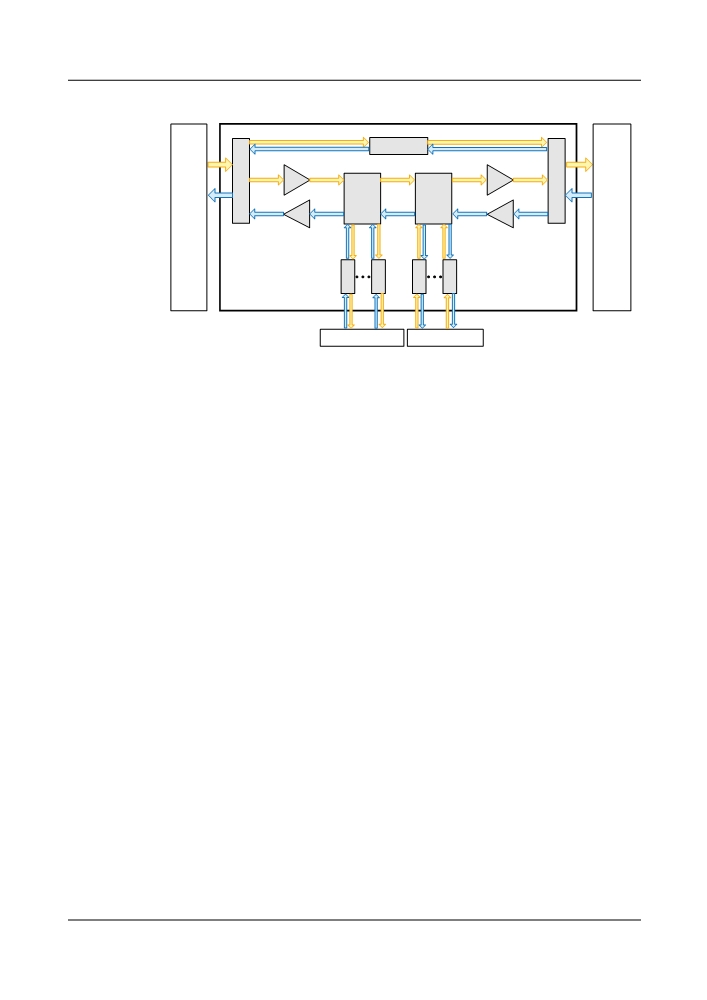
Figure 6-9 Schematic diagram of DWDM FOADM node with OADM boards
SC2
FIU
OA
OA
FIU
West
OADM
OADM
East
line-side
Unit
Unit
line-side
ODF
OA
OA
ODF
O
O
O
O
T
T
T
T
U
U
U
U
West client-side
East client-side
OTU: optical transponder unit
FIU: fiber interface unit
SC2: bidirectional OSC unit
OA: optical amplifier unit
OADM unit: OADM unit(s)
ODF: Optical distribution frame
Typical Configuration
Take an FOADM node (installed with optical add/drop multiplexing boards) that adds/drops
and multiplexes eight wavelengths in either of the two transmit directions for example, as shown
in Figure 6-10.
196
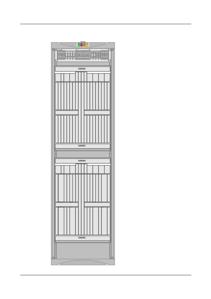
Figure 6-10 Typical configuration of the FOADM equipment that consists of the optical add/
drop multiplexing units
FAN
A
S
S
EFI2EF
PIU
PIU
U
T
T
PIU
PIU
STI
ATE
I1
X
G
G
O
O
O
O
O
O
O
O
S
O
O
O
O
O
O
O
O
T
T
T
T
T
T
T
T
C
T
T
T
T
T
T
T
T
U
U
U
U
U
U
U
U
C
U
U
U
U
U
U
U
U
X
X
C
C
H
H
S
C
C
FAN
FAN
A
S
S
EFI2EF
PIU
PIU
U
T
T
PIU
PIU
STI
ATE
I1
X
G
G
S
C
C
O
O
M
M
O
O
F
S
S
F
A
B
R
R
B
A
I
C
C
I
U
U
8
8
U
U
U
2
C
U
1
1
V
V
1
1
FAN
197
6.4 ROADM in a DWDM System
The OptiX OSN 8800 provides ROADM equipment.
6.4.1 ROADM Node with WSD9 Board and WSM9 Board (40-
Wavelength)
Functions
The reconfigurable optical add or drop multiplexer (ROADM) with WSS technology can add
and drop channels dynamically within a ring network. It supports up to eight-dimensional
grooming and extensions between ring networks.
The WSD9 realizes dynamic and configurable demultiplexing of any wavelength to any port.
The board can output any wavelength group at any node in ring networks and chain networks.
After that, it can distribute any output wavelength to any port to achieve genuine dynamic
wavelength distribution.
The WSM9 realizes dynamic and configurable multiplexing of any wavelength to any port. The
board can input any wavelength group at any node in ring networks and chain networks. Any
wavelength can be input through any port of the WSM9. It can achieve genuine dynamic
wavelength distribution.
The ROADM formed by the WSD9 and the WSM9 can be adopted in center sites or edge sites.
It has the following advantages:
l Flexible expansion without service interruption
l Low operation cost
l Adjustment of wavelength adding/dropping and passing through status by NM software to
achieve remote dynamic adjustment of wavelength status
Functional Units
An ROADM system with 40 wavelengths, which consists of WSD9 and WSM9 boards, has the
following units:
l Optical transponder unit (OTU)
l Optical amplifier unit (OA)
l Bidirectional optical supervisory channel unit (SC2)
l Fiber interface unit (FIU)
l Optical add/drop multiplexer or optical multiplexer and demultiplexer (OADM/OM/OD)
l
9-port wavelength selective switching multiplexing board (WSM9)
l
9-port wavelength selective switching demultiplexing board (WSD9)
l System control and communication unit (SCC)
For the boards used in each unit, see 4.2 Hardware Architecture.
198
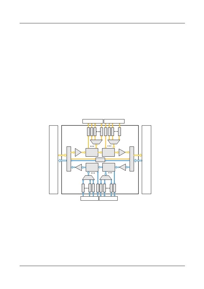
Signal Flow
ROADMs process optical signals in two transmission directions.
The FIU board separates optical supervisory signals and the main path signals from the received
line signals. The optical supervisory signals are sent to the optical supervisory units for
processing. The main path signals are amplified and sent to the WSD9 board.
The wavelengths that need to be dropped locally are output from the specified ports according
to the configuration. The multiplexed signals output from the WSD9 board are demultiplexed
to single wavelengths by the demultiplexer or OADM unit before entering the OTU and the local
client equipment. The single wavelengths output from the WSD9 board are sent to the client
equipment directly through the OTU board.
The other wavelengths are not added/dropped locally. They pass through and are multiplexed
with the wavelength input by the WSM9 before optical amplification. Then they are multiplexed
with the processed optical supervisory signals for line transmission.
Figure 6-11 shows the functional modules of this type of ROADM.
Figure 6-11 Schematic diagram of ROADM node with the WSM9 board and WSD9 board
West client-side
East client-side
O
O
O
O
O
O
O
O
T
T
T
T
T
T
T
T
U
U
U
U
U
U
U
U
OD
OM
West
OA
WSD9
WSM9
OA
East
line-side
line-side
ODF
FIU
FIU
SC2
ODF
OA
WSM9
WSD9
OA
OM
OD
O
O
O
O
O
O
O
O
T
T
T
T
T
T
T
T
U
U
U
U
U
U
U
U
West client-side
East client-side
FIU: fiber interface unit
OA: optical amplifier unit
SC2: bidirectional OSC unit
OD: optical demultiplexer
OM: optical multiplexer
OTU: optical transponder unit
WSD9: 9-port wavelength selective
WSM9: 9-port wavelength selective
ODF: optical distribution frame
switching demultiplexing board
switching multiplexing board
Typical Configuration
The two-dimensional ROADM equipment (40 wavelengths), which can add/drop 30% services
and is formed by the WSD9 and WSM9, is taken for example. Figure 6-12 shows the typical
configuration. One cabinet and two subracks are required.
199
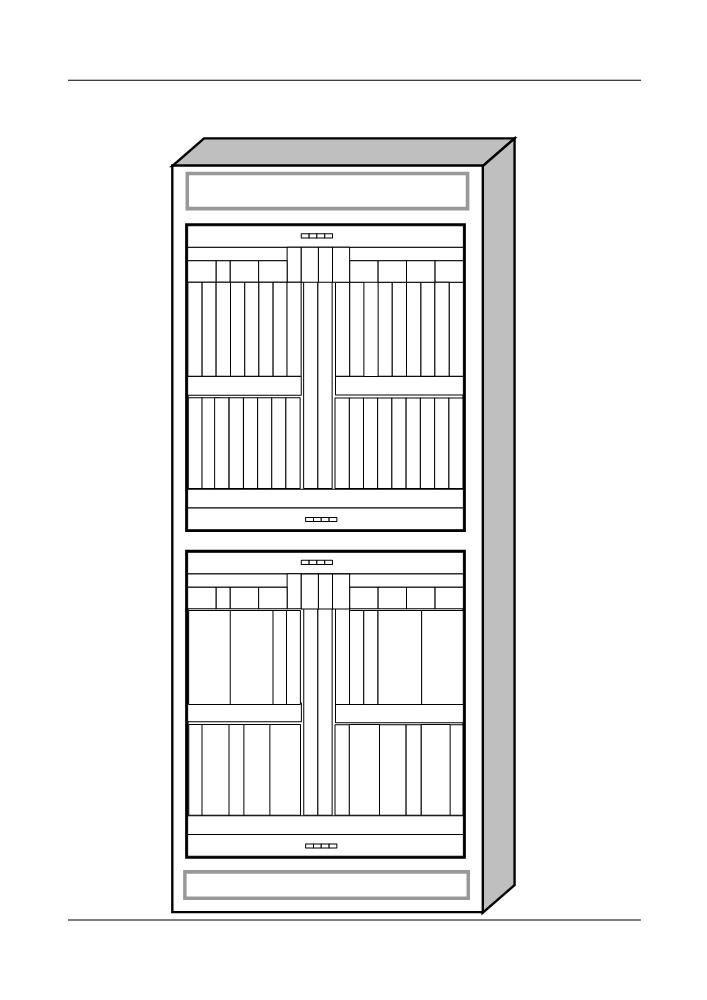
Figure 6-12 Typical configuration of the ROADM equipment that consists of the WSD9 and
the WSM9 boards (40 wavelengths)
FAN
A
S
S
EF
U
T
T
EFI2
PIU
PIU
PIU
PIU
STI
ATE
I1
X
G
G
N
N
N
N
N
N
N
N
S
N
N
N
N
N
N
N
N
Q
Q
Q
Q
Q
Q
Q
Q
C
Q
Q
Q
Q
Q
Q
Q
Q
2
2
2
2
2
2
2
2
C
2
2
2
2
2
2
2
2
X
X
C
C
H
H
/
/
X
X
C
C
M
M
T
T
T
T
T
T
T
T
S
Q
Q
Q
Q
O
O
O
O
C
X
X
X
X
M
M
M
M
C
FAN
FAN
A
S
S
EF
U
T
T
EFI2
PIU
PIU
PIU
PIU
STI
ATE
I1
X
G
G
S
S
M40
D40
C
C
D40
M40
C
2
O
O
O
W
W
W
W
O
F
B
S
B
F
A
S
S
S
S
A
I
U
C
U
I
U
M
D
D
M
U
U
C
U
1
9
9
9
9
1
1
1
FAN
200
6.4.2 ROADM Node with WSD9 Board and WSM9 Board (80-
Wavelength)
Functions
The reconfigurable optical add or drop multiplexer (ROADM) with WSS technology can add
and drop channels dynamically within a ring network. It supports up to eight-dimensional
grooming and extensions between ring networks.
The WSD9 realizes dynamic and configurable demultiplexing of any wavelength to any port.
The board can output any one of the wavelength groups at any node in ring networks and chain
networks. After that, it can distribute any output wavelength to a port to achieve genuine dynamic
wavelength distribution.
The WSM9 realizes dynamic and configurable multiplexing of any wavelength to any port. The
board can input any one of the wavelength groups at any node in ring networks and chain
networks. After that, it can distribute any input wavelength to a port to achieve genuine dynamic
wavelength distribution.
The ROADM formed by the WSD9 and the WSM9 can be adopted in center sites or edge sites.
It has the following advantages:
l Flexible expansion without service interruption
l Low operation cost
l Adjustment of wavelength adding/dropping and passing through status by NM software to
realize remote dynamic adjustment of wavelength status
Functional Units
An ROADM system with 80 wavelengths, which consists of WSD9 and WSM9 boards, has the
following units:
l Optical transponder unit (OTU)
l Optical amplifier unit (OA)
l Bidirectional optical supervisory channel unit (SC2)
l Fiber interface unit (FIU)
l Fixed optical add/drop multiplexer or optical multiplexer and demultiplexer (OADM/OM/
OD)
l Interleaver unit (ITL)
l
9-port wavelength selective switching multiplexing board (TN13WSM9)
l
9-port wavelength selective switching demultiplexing board (TN13WSD9)
l System control and communication unit (SCC)
For the boards used in each unit, see 4.2 Hardware Architecture.
Signal Flow
ROADMs process optical signals in two transmission directions.
201