Huawei OptiX BWS 1600G. Technical Description - part 18

6 Technical Specifications
EN 60825-2 Safety of Laser Products - Part 2: Safety of Optical Fibre
Communication Systems
EMC Standards
ETSI EN300 386-1.2.1 (2000)
-
CISPR55022 (1999)
-
FCC PART 15 including:
-
Radiation emission (RE):
CISPR22, ETSI EN 300 127 (V1.2.1)
Conduction emission (CE):
CISPR22, ETSI EN 300 386--1.2.1
Electric static discharge (ESD):
IEC61000-4-2
Fast transient pulse string (EFT/B):
IEC61000-4-4
Conductive susceptibility (CS):
IEC61000-4-6
Radiation sensitivity (RS):
IEC61000-4-3
Surge:
IEC61000-4-5
Voltage drop (DIP):
IEC61000-4-29 (DC)
Power induction (PI):
ITU K.20
Power magnetic field sensitivity (PMS):
IEC61000-4-8
These standards are applied for communication equipment production:
IEC 61000-4-6 (1996)
-
IEC 61000-4-3 (1995)
-
IEC 61000-4-2 (1995)
-
IEC 61000-4-5 (1995)
-
IEC 61000-4-8 (1993)
-
IEC 61000-4-29 (2000)
-
IEC 61000-4-4 (1995)
-
IEC 61000-3-2 (1995)
-
IEC 61000-3-3 (1995)
-
ETSI EN 300 127 (V1.2.1)
-
ITU k.20
-
6-70
6 Technical Specifications
6.14 Environment Requirement
This environment requirement is set by referring to the following international
standards:
(1) GF 014-95: Environment conditions of the telecommunication equipment room
(2) ETS 300 019-1-3: Class 3.2 Partly temperature-controlled locations
(3) NEBS GR-63-CORE: Network Equipment-Building System (NEBS)
Requirements: Physical Protection
6.14.1 Storage Environment
Climate Environment
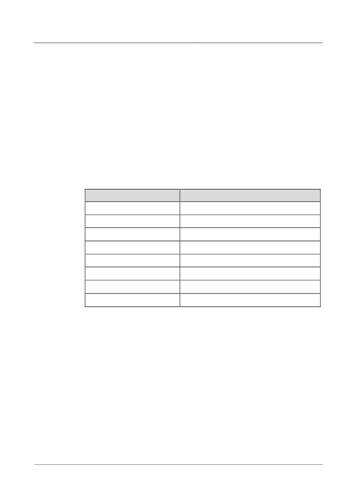
Table 6-87 Requirements for climate environment
Item
Range
Altitude
≤5000 m
Air pressure
70 kPa-106 kPa
Temperature
-40°C-+70°C
Temperature change rate
≤1°C /min
Relative Humidity
10%-100%
Solar radiation
≤1120 W/s²
Heat radiation
≤600 W/s²
Wind speed
≤30 m/s
Waterproof Requirement
(1) Equipment storage requirements at the customer site: Generally the equipment
is stored indoors.
(2) Where there is no water on the floor and no water leakage on the packing boxes
of the equipment. The equipment should not be stored in places where leakage is
probable, such as near the auto firefighting and heating facilities.
(3) If the equipment is required to be stored outdoors, the following four conditions
should be met at the same time:
The packing boxes are intact.
Necessary rainproof measures should have been taken to prevent rainwater
from entering the packing boxes.
6-71
6 Technical Specifications
There is no water on the ground where the packing boxes are stored, let alone
water entering into the packing boxes.
The packing boxes are not directly exposed to the sun.
Biologic Environment
(1) Avoiding the reproduction of animalcule, such as epiphyte and mildew.
(2) Getting rid of rodent (such as mouse).
Clarity of Air
(1) No explosive, conductive, magnetic conductive nor corrosive dust.
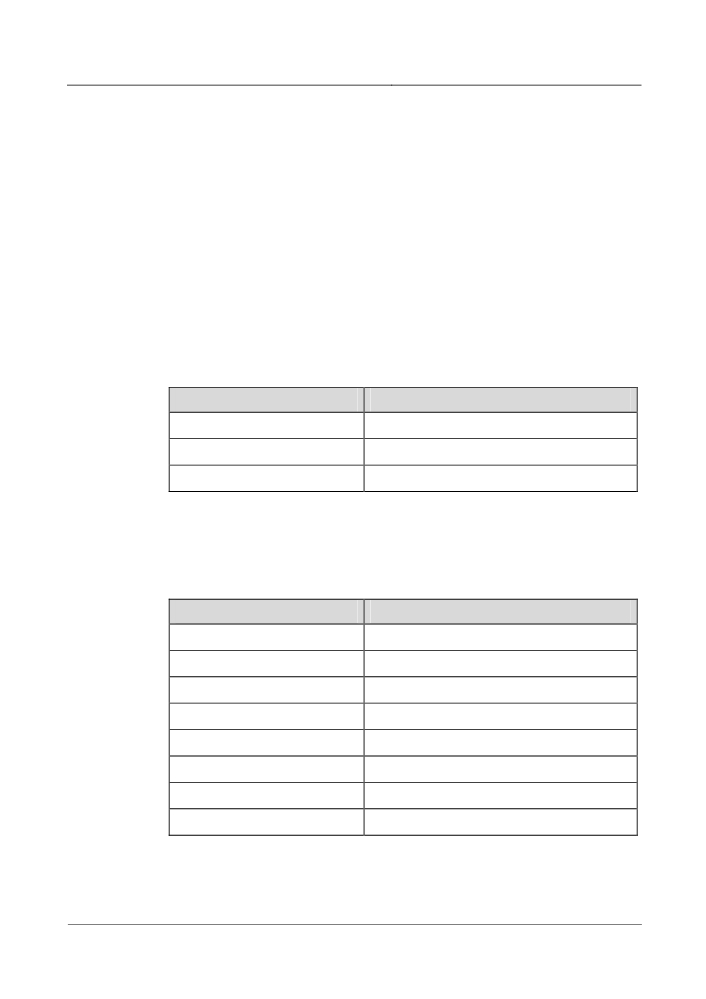
(2) The density of mechanical active substance complies with the requirements of
Table 6-88.
Table 6-88 Requirements for the density of mechanical active substance
Mechanical active substance
Content
Suspending dust
≤5.00 mg/m³
Precipitable dust
≤20.0 mg/m²·h
Sand
≤300 mg/m³
(3) The density of chemical active substance complies with the requirements of
Table 6-89.
Table 6-89 Requirements for the density of chemical active substance
Chemical active substance
Content
SO2
≤0.30 mg/m³
H2S
≤0.10 mg/m³
NO2
≤0.50 mg/m³
NH3
≤1.00 mg/m³
CI2
≤0.10 mg/m³
HCI
≤0.10 mg/m³
HF
≤0.01 mg/m³
O3
≤0.05 mg/m³
6-72
6 Technical Specifications
Mechanical Stress
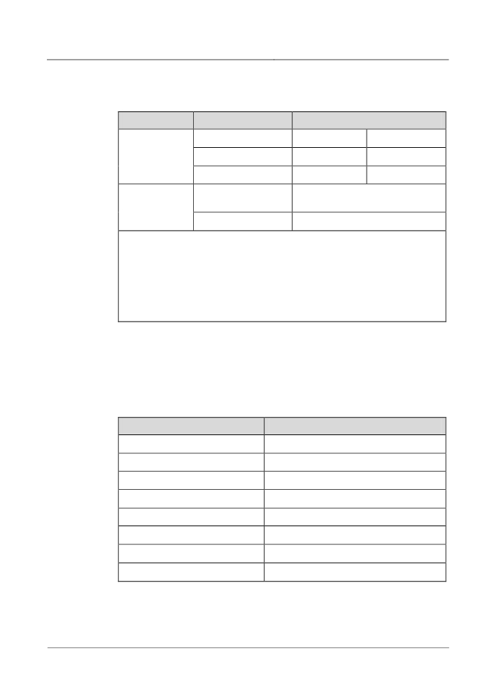
Table 6-90 Requirements for mechanical stress
Item
Subitem
Range
Sinusoidal
Displacement
≤7.0 mm
-
vibration
Acceleration
-
≤20.0 m/s²
Frequency range
2 Hz-9 Hz
9 Hz-200 Hz
Non-steady
Impact response
≤250 m/s²
impact
spectrum II
Static load
≤5 kPa
Note:
Impact response spectrum: the curve of the maximum acceleration response generated
by the equipment under the stipulated impact motivation. Impact response spectrum II
indicates the duration of semi sinusoidal impact spectrum is 6ms.
Static load: The pressure from upside, that the equipment with package can endure
when the equipment is piled as per stipulation.
6.14.2 Transport Environment
Climate Environment
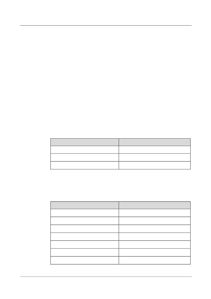
Table 6-91 Requirements for climate environment
Item
Range
Altitude
≤5000 m
Air pressure
70 kPa-106 kPa
Temperature
-40°C-+70°C
Temperature change rate
≤3°C /min
Relative Humidity
10%-100%
Solar radiation
≤1120 W/s²
Heat radiation
≤600 W/s²
Wind speed
≤30 m/s
6-73
6 Technical Specifications
Waterproof Requirement
The following conditions should be met during the transportation:
The packing boxes are intact.
Necessary rainproof measures should be taken for the means of transport to
prevent rainwater from entering the packing boxes.
There is no water in the means of transportation.
Biologic Environment
(1) Avoiding the reproduction of animalcule, such as epiphyte and mildew.
(2) Getting rid of rodent (such as mouse).
Clarity of Air
(1) No explosive, conductive, magnetic conductive nor corrosive dust.
(2) The density of mechanical active substance complies with the requirements of
Table 6-92.
Table 6-92 Requirements on the density of mechanical active substance
Mechanical active substance
Content
Suspending dust
No requirement
Precipitable dust
≤3.0 mg/m²·h
Sand
≤100 mg/m³
(3) The density of chemical active substance complies with the requirements of
Table 6-93.
Table 6-93 Requirements for the density of mechanical active substance
Chemical active substance
Content
SO2
≤0.30 mg/m³
H2S
≤0.10 mg/m³
NO2
≤0.50 mg/m³
NH3
≤1.00 mg/m³
CI2
≤0.10 mg/m³
HCI
≤0.10 mg/m³
HF
≤0.01 mg/m³
6-74
6 Technical Specifications
Chemical active substance
Content
O3
≤0.05 mg/m³
Mechanical Stress
Table 6-94 Requirements for mechanical stress
Item
Subitem
Range
Sinusoidal
Displacement
≤7.5 mm
-
-
vibration
Acceleration
-
≤20.0 m/s²
≤40.0 m/s²
Frequency range
2 Hz-9 Hz
9 Hz-200 Hz
200 Hz-500
Hz
Random
Acceleration
10 m²/s³
3 m²/s³
1 m²/s³
vibration
spectrum density
Frequency range
2 Hz-9 Hz
9 Hz-200 Hz
200 Hz-500
Hz
Non-steady
Impact response
≤300 m/s²
impact
spectrum II
Static load
≤10 kPa
Note:
Impact response spectrum: the curve of the maximum acceleration response generated
by the equipment under the stipulated impact motivation. Impact response spectrum II
indicates the duration of semi sinusoidal impact spectrum is 6ms.
Static load: The pressure from upside, that the equipment with package can endure
when the equipment is piled as per stipulation.
6.14.3 Operation Environment
Climate Environment
Table 6-95 Requirements for temperature, humidity
Equipment
Temperature
Relative humidity
name
Long-term
Short-term
Long-term
Short-term
operation
operation
operation
operation
0°C-40°C
-5°C-45°C
10%-90%
5%-95%
6-75
6 Technical Specifications
Equipment
Temperature
Relative humidity
name
Long-term
Short-term
Long-term
Short-term
operation
operation
operation
operation
Note:
Testing point of product temperature and humidity: when the cabinet of the product
has no protection board in the front and at the back, the value is tested 1.5 meter
above the floor and 0.4 meter in front of the cabinet.
Short-term working condition means that the successive working time does not exceed
96 hours and the accumulated time every year does not exceed 15 days.
Table 6-96 Other requirements for climate environment
Item
Range
Altitude
≤4000 m
Air pressure
70-106 kPa
Temperature change rate
≤5°C /h
Solar radiation
≤700 W/s²
Heat radiation
≤600 W/s²
Wind speed
≤1 m/s
Biologic Environment
(1) Avoiding the reproduction of animalcule, such as epiphyte and mildew.
(2) Getting rid of rodent (such as mouse).
Clarity of Air
(1) No explosive, conductive, magnetic conductive nor corrosive dust.
(2) The density of mechanical active substance complies with the requirements of
Table 6-97.
Table 6-97 Requirements for the density of mechanical active substance
Mechanical active substance
Content
Dust particle
≤3 × 10⁵ /m³
Suspending dust
≤0.4 mg/m³
6-76
6 Technical Specifications
Mechanical active substance
Content
Precipitable dust
≤15 mg/m²·h
Sand
≤100 mg/m³
(3) The density of chemical active substance complies with the requirements of
Table 6-98.
Table 6-98 Requirements for the density of mechanical active substance
Chemical active substance
Content
SO2
≤0.20 mg/m³
H2S
≤0.006 mg/m³
NH3
≤0.05 mg/m³
CI2
≤0.01 mg/m³
HCI
≤0.10 mg/m³
HF
≤0.01 mg/m³
O3
≤0.005 mg/m³
CO
≤5.0 mg/m³
Mechanical Stress
Table 6-99 Requirements for mechanical stress
Item
Subitem
Range
Sinusoidal vibration
Displacement
≤3.5 mm
-
Acceleration
-
≤10.0 m/s²
Frequency range
2-9 Hz
9-200 Hz
Non-steady impact
Impact response spectrum II
≤100 m/s²
Static load
0
6-77
6 Technical Specifications
Item
Subitem
Range
Note:
Impact response spectrum: the curve of the maximum acceleration response generated
by the equipment under the stipulated impact motivation. Impact response spectrum II
indicates the duration of semi sinusoidal impact spectrum is 6ms.
Static load: The pressure from upside, that the equipment with package can endure
when the equipment is piled as per stipulation.
6-78
A Measures in DWDM Network Designing
A
Measures in DWDM Network
Designing
A.1 Dispersion Limited Distance
Chromatic Dispersion
Chromatic dispersion is a dominant factor restricting the transmission distance. It is
caused by the characteristics of the transmitting optical source and transmission
media (optical fibre).
Transmission Restriction
With the increasing transmission rate in the optical fibre system and the cascading
of multiple EDFAs in the optical transmission system, the overall dispersion and
related dispersion costs in the transmission link will become higher. This is a
serious issue. At present, dispersion limitation has become a vital factor in deciding
many system regeneration section distances. In the single module optical fibre, the
dispersion mainly includes material dispersion and wave-guide dispersion, which
might cause different time delays in different frequencies. In terms of time domain,
this might lead to the extension of optical pulses, which can cause the interference
between optical pulses. The result is the deterioration of transmitted signals.
Effect-Reducing Method
In some optical amplification sub-systems, the passive dispersion compensation
device can be combined with the optical amplifier. This sub-system will add limited
chromatic dispersion to the system, making the dispersion coefficient reverse to the
original one and reducing the system chromatic dispersion. This device can be
mounted together with EDFA to compensate for the loss related with the passive
dispersion compensation. In addition, the use of G.655 and G.653 optical fibres, are
beneficial to minimise the chromatic dispersion.
A-1
A Measures in DWDM Network Designing
Network Design Consideration
During the DWDM network design, the whole network is divided into several
regeneration sections. Each section should be less than the dispersion-restricted
distance of the optical source. Thus the dispersion of the whole network can be
tolerated.
Tips
In dispersion calculation, for G.652 fibres, the typical dispersion coefficient in 1550
nm window is 17 ps/nm.km. In engineering design, the budget should be 20
ps/nm.km.
A.2 Signal Power
Long-distance transmission of the optical signals requires that the signal power be
enough to offset optical fibre loss. It is natural, that with distance increasing, the
optical power becomes less and less. This phenomenon is known as attenuation.
The attenuation coefficient of the G.652 optical fibre in the 1550 nm window is
generally about 0.25 dB/km. Considering the optical connector, optical fibre
redundancy and other factors, the composite optical fibre attenuation coefficient is
usually less than 0.275 dB/km.
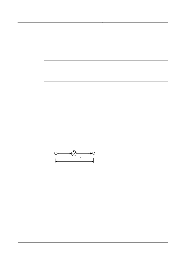
In specific calculation, power budget is normally calculated between two adjacent
equipments in the transmission network. The distance (loss) between two adjacent
equipments in a transmission network, is called trunk distance (loss).
S
R
Node A
Node B
P
P
out
in
L
Figure A-1 Trunk loss calculation principle
If Pout is the output power (dBm) of a single channel at point S, and Pin is the
minimum allowed input power (dBm) of a single channel at point R, then
Regenerator distance = (Pout - Pin) /a
Where “a” is the accumulative attenuation of optical cables (dB/km) per km
(according to relevant ITU-T recommendation, a=0.275 dB/km).
Power budget calculations are used to determine distance between regeneration
sections.
A-2