Yamaha XV1700P, XV1700PC. Service Manual - part 18
 

  Index      Manuals     Yamaha XV1700P, XV1700PC. Service Manual


Search            copyright infringement  


Content      ..     16      17      18      19     ..


Yamaha XV1700P, XV1700PC. Service Manual - part 18


5 - 6

ENG

8

7

6

1

3

4

3

5

2

T


R

.

.

7 Nm (0.7 m


 kg, 5.1 ft 

 Ib)

T


R

.

.

7 Nm (0.7 m


 kg, 5.1 ft 

 Ib)

Order

Job/Part

Q’ty

Remarks

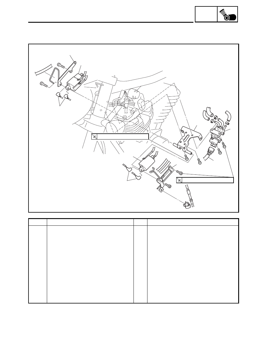
Removing the ignition coil and 
linear control valve

Remove the parts in the order listed.

1

Hose bracket

1

2

Wire harness bracket

1

3

Ignition coil connector

4

Disconnect.

4

Ignition coil 1

1

5

Ignition coil 2

1

6

Linear control valve coupler

1

Disconnect.

7

Linear control valve

1

8

Linear control valve bracket

1

For installation, reverse the removal 
procedure.

ENGINE

5 - 7

ENG

18

5

7

6

7

4

17

8

9

11

13

16

9

9

15

14

12

10

6

8

11

T


R

.

.

88 Nm (8.8 m 


kg, 64 ft


Ib)

R

.

.

98 Nm (9.8 m 


kg, 71 ft


Ib)

T


R

.

.

53 Nm (5.3 m 


kg, 38 ft


Ib)

T


R

.

.

88 Nm (8.8 m 


kg, 64 ft


Ib)

E

T


R

.

.

105 Nm (10.5 m 

 kg, 75 ft 

 lb)

T


R

.

.

48 Nm (4.8 m 


kg, 35 ft


Ib)

T


R

.

.

18 Nm (1.8 m 


kg, 13 ft


Ib)

2

1

3

1

R

.

.

48 Nm (4.8 m 


kg, 35 ft


Ib)

Order

Job/Part

Q’ty

Remarks

Removing the engine 

Remove the parts in the order listed. 

NOTE:

Place a suitable stand under the frame
and engine. 

1

Upper mounting bolt

2

2

Upper mounting bracket bolt

2

3

Upper mounting 

1

4

Self-locking nut

1

5

Front mounting bolt

1

Refer to “INSTALLING THE ENGINE”.

6

Front engine bracket self-locking nut

4

7

Front engine bracket

2

8

Front engine bracket bolt

4

9

Self-locking nut

3

10

Upper rear mounting bolt

1

ENGINE

5 - 8

ENG

18

5

7

6

7

4

17

8

9

11

13

16

9

9

15

14

12

10

6

8

11

T


R

.

.

88 Nm (8.8 m 


kg, 64 ft


Ib)

R

.

.

98 Nm (9.8 m 


kg, 71 ft


Ib)

T


R

.

.

53 Nm (5.3 m 


kg, 38 ft


Ib)

T


R

.

.

88 Nm (8.8 m 


kg, 64 ft


Ib)

E

T


R

.

.

105 Nm (10.5 m 

 kg, 75 ft 

 lb)

T


R

.

.

48 Nm (4.8 m 


kg, 35 ft


Ib)

T


R

.

.

18 Nm (1.8 m 


kg, 13 ft


Ib)

2

1

3

1

R

.

.

48 Nm (4.8 m 


kg, 35 ft


Ib)

Order

Job/Part

Q’ty

Remarks

11

Rear engine bracket nut

2

Refer to “INSTALLING THE
ENGINE”.

12

Rear engine bracket bolt

2

13

Rear engine bracket (left)

1

14

Rear engine bracket (right)

1

15

Spacer bolt

1

Loosen.

16

Lower rear mounting bolt

1

17

Lower front mounting bolt

1

18

Engine

1

For installation, reverse the removal 
procedure.

ENGINE

5 - 9

ENG

EAS00192

INSTALLING THE ENGINE

1. Install: 

• spacer bolt 

1


• lower front mounting bolt 

2


• lower rear mounting bolt 

3


2. Tighten:

• spacer bolt 

1


NOTE:

• Tighten the spacer bolt 

1

 to specification

with a pivot shaft wrench 

4

.

• When tightened, the spacer bolt 

1

 should be

flat against the engine surface.

3. Install:

• self-locking nut 

5

6

• rear engine bracket (left) 

7


• rear engine bracket (right) 

8


• upper rear mounting bolt 

9

• self-locking nut 

0

• front engine bracket 

A

• front mounting bolt 

B

• self-locking nut 

C


• upper engine bracket 

D


• upper mounting bolts 

E


NOTE:

Do not fully tighten the bolts and nuts. 

4. Tighten:

• upper mounting bolts 

E


• upper engine bracket bolts 

F


5. Tighten:

• self-locking nut 

5

• self-locking nut 

6

• nuts 

G

• self-locking nut 

0

• self-lock nuts 

H


• self-locking nut 

C

Pivot shaft wrench

YM-01485

9

8

6

5

1

H

C

A

2

G

G

3

0

F

E

E

D

7

B

A

H

T


R

.

.

18 Nm (1.8 m  •  kg, 13 ft  •  lb)

T


R

.

.

48 Nm (4.8 m  •  kg, 35 ft  •  lb)

T


R

.

.

48 Nm (4.8 m  •  kg, 35 ft  •  lb)

T


R

.

.

105 Nm (10.5 m  •  kg, 75 ft  •  lb)

T


R

.

.

88 Nm (8.8 m  •  kg, 64 ft  •  lb)

T


R

.

.

53 Nm (5.3 m  •  kg, 38 ft  •  lb)

T


R

.

.

98 Nm (9.8 m  •  kg, 71 ft  •  lb)

T


R

.

.

48 Nm (4.8 m  •  kg, 35 ft  •  lb)

T


R

.

.

88 Nm (8.8 m  •  kg, 64 ft  •  lb)

ENGINE

5 - 10

ENG

6. Connect:

• oil tank breather hose 

1

• cylinder head breather hose 

2

• spark plug caps 

3

NOTE:

Refer to “CABLE ROUTING” in chapter 2.

2

3

1

3

INSTALLING THE MUFFLER AND 
EXHAUST PIPES

1. Install:

• gaskets
• exhaust pipes

NOTE:

Finger tighten the exhaust pipe nuts and bolts.

2. Install:

• muffler
• bolt 

1

• bolts 

2

T


R

.

.

53 Nm (5.3 m  •  kg, 38 ft  •  lb)

T


R

.

.

20 Nm (2.0 m  •  kg, 14 ft  •  lb)

3. Tighten:

• exhaust pipe nuts

• exhaust pipe bolts

• clamp bolts 

1

T


R

.

.

20 Nm (2.0 m  •  kg, 14 ft  •  lb)

T


R

.

.

24 Nm (2.4 m  •  kg, 17 ft  •  lb)

T


R

.

.

12 Nm (1.2 m  •  kg, 8.7 ft  •  lb)

ENGINE

5 - 11

ENG

ROCKER ARMS, PUSH RODS AND VALVE LIFTERS 

11

10

12

13

14

11

9

2

1

1

2

7 8

6

5

4

T


R

.

.

10 Nm (1.0 m 


kg, 7.2 ft


Ib)

T


R

.

.

18 Nm (1.8 m 


kg, 13 ft


Ib)

T


R

.

.

12 Nm (1.2 m 


kg, 8.7 ft


Ib)

T


R

.

.

10 Nm (1.0 m 


kg, 7.2 ft


Ib)

T


R

.

.

48 Nm (4.8 m 


kg, 35 ft


Ib)

(5)

(4)

3

New

Order

Job/Part

Q’ty

Remarks

Removing the engine left side cover 
and camshaft sprocket cover

Remove the parts in the order listed.

Seat/fuel tank/silencer air filter case

Refer to “SEAT AND SIDE COVERS”, 
“FUEL TANK” and “SILENCER AIR FIL-
TER CASE” in chapter 3.

Muffler/exhaust pipes

Refer to “ENGINE”.

Engine oil

Drain.
Refer to “CHANGING THE ENGINE OIL”
in chapter 3.

1

Spark plug cap

2/2

Disconnect.

Refer to “INSTALLING THE 
CAMSHAFT SPROCKET 
COVER AND ENGINE 
LEFT SIDE COVER”.

2

Spark plug

4

3

Shift rod

1

4

Rider footrest assembly (left)

1

5

Canister

1

For califor-
nia only.

ROCKER ARMS, PUSH RODS AND VALVE LIFTERS

5 - 12

ENG

11

10

12

13

14

11

9

2

1

1

2

7 8

6

5

4

T


R

.

.

10 Nm (1.0 m 


kg, 7.2 ft


Ib)

T


R

.

.

18 Nm (1.8 m 


kg, 13 ft


Ib)

T


R

.

.

12 Nm (1.2 m 


kg, 8.7 ft


Ib)

T


R

.

.

10 Nm (1.0 m 


kg, 7.2 ft


Ib)

T


R

.

.

48 Nm (4.8 m 


kg, 35 ft


Ib)

(5)

(4)

3

New

Order

Job/Part

Q’ty

Remarks

6

Engine left side cover

1

Refer to “INSTALLING THE CAMSHAFT 
SPROCKET COVER AND ENGINE 
LEFT SIDE COVER”.

7

Rubber damper

1

8

Timing mark accessing screw

1

9

Crankshaft end cover

1

10

Decompression solenoid cover

1

11

Camshaft sprocket cover 1

1

12

Dowel pin

2

13

Cylinder identification sensor

1

14

Camshaft sprocket cover 2

1

15

Camshaft sprocket cover gasket

1

For installation, reverse the removal 
procedure

ROCKER ARMS, PUSH RODS AND VALVE LIFTERS

5 - 13

ENG

9

8

6

5 4

2

5

4 3

1

3 4

5

5

4

5

9

5

3

4

5

4

4

5

5

3

5

8

7

T


R

.

.

10 Nm (1.0 m 


kg, 7.2 ft


Ib)

New

New

Order

Job/Part

Q’ty

Remarks

Removing cylinder head covers

Remove the parts in the order listed.

Ignition coil/rectifier/regulator/
liner control valve

Refer to “ENGINE”.

1

Cylinder head breather hose

1

2

Oil tank breather hose

1

3

Bolt

4

 = 60 mm (2.36 in)

4

Bolt

12

 = 50 mm (1.97 in)

5

Bolt

12

 = 40 mm (1.57 in)

6

Rear cylinder head cover

1

Refer to “INSTALLING THE CYLINDER 
HEAD COVERS”.

7

Front cylinder head cover

1

8

Cylinder head cover gasket

2

9

Dowel pin

4

For installation, reverse the removal 
procedure

ROCKER ARMS, PUSH RODS AND VALVE LIFTERS

5 - 14

ENG

10

11

8

9

10

11

7

10

11

10

11

8

9

3

5

6

6

4

5

1

2

1

E

E

E

E

E

E

E

T


R

.

.

24 Nm (2.4 m 


kg, 17 ft


Ib)

T


R

.

.

10 Nm (1.0 m 


kg, 7.2 ft


Ib)

T


R

.

.

20 Nm (2.0 m 


kg, 14 ft


Ib)

New

New

7

Order

Job/Part

Q’ty

Remarks

Removing the push rods and rocker 
arms

Remove the parts in the order listed.

1

Push rod 1

3

 = 288.5 mm (11.358 in) blue painting

2

Push rod 2

1

 = 290.5 mm (11.437 in) yellow painting

3

Rear rocker arm base

1

Refer to “REMOVING THE ROCKER 
ARMS, PUSH RODS AND VALVE LIFT-
ERS” and “INSTALLING THE ROCKER 
ARMS AND PUSH RODS”.

4

Front rocker arm base

1

5

Rocker arm base gasket

2

6

Dowel pin

4

7

Rocker arm shaft

4

8

Rocker arm 1

2

9

Rocker arm 2

2

10

Locknut

2

11

Adjusting screw

2

For installation, reverse the removal 
procedure

ROCKER ARMS, PUSH RODS AND VALVE LIFTERS

5 - 15

ENG

2

3

1

2

7

6

4

5

2

1

3

2

7

E

E

T


R

.

.

10 Nm (1.0 m 


kg, 7.2 ft


Ib)

T


R

.

.

10 Nm (1.0 m 


kg, 7.2 ft


Ib)

E

E

E

E

Order

Job/Part

Q’ty

Remarks

Removing the valve lifters

Remove the parts in the order listed.

1

Push rod cover

2

2

O-ring

4

3

Seal

2

4

Air filter bracket

1

5

Rear valve lifter case

1

6

Front valve lifter case

1

7

Valve lifter

4

Refer to “REMOVING THE ROCKER 
ARMS, PUSH RODS AND VALVE LIFT-
ERS” and “INSTALLING THE VALVE 
LIFTERS”.
For installation, reverse the removal 
procedure

ROCKER ARMS, PUSH RODS AND VALVE LIFTERS

5 - 16

ENG

REMOVING THE ROCKER ARMS, PUSH 
RODS AND VALVE LIFTERS

1. Align:

• TDC mark 

a

 on the crankshaft position

sensor rotor
(with the pointer 

b

 on the clutch/crankshaft

position sensor rotor cover)

▼▼▼

▼ ▼▼▼

▼ ▼▼▼

▼ ▼▼▼

▼ ▼▼▼

▼ ▼▼▼

▼▼▼

a. Turn the crankshaft clockwise.
b. When piston #1 is at TDC on the compres-

sion stroke, align the TDC mark 

a

 on the

crankshaft position sensor rotor with the
pointer 

b

 on the clutch/crankshaft position

sensor rotor cover.

c. Check the camshaft drive gear mark 

c

position and camshaft driven gear mark 

d

position as shown.
If the marks are not aligned, turn the crank-
shaft counterclockwise 360 degrees and
recheck step b.

▲▲▲

▲ ▲▲▲

▲ ▲▲▲

▲ ▲▲▲

▲ ▲▲▲

▲ ▲▲▲

▲▲▲

2. Remove:

• rocker arm bases

(with the rocker arms)

3. Remove:

• valve lifters

NOTE:

Make a note of the position of each valve lifter
so that they can be installed in the correct
place.

CAUTION:

Do not lay the removed valve lifter on its
side.

d

c

CHECKING THE ROCKER ARMS AND 
ROCKER ARM SHAFTS

The following procedure applies to all of the
rocker arms and rocker arm shafts.
1. Check:

• rocker arm

Damage/wear 

 Replace.

ROCKER ARMS, PUSH RODS AND VALVE LIFTERS

5 - 17

ENG

2. Check:

• rocker arm shaft

Blue discoloration/excessive wear/pitting/
scratches 

 Replace or check the lubrica-

tion system.

3. Measure:

• rocker arm inside diameter 

a


Out of specification 

 Replace.

Rocker arm inside diameter

18.000 ~ 18.018 mm 
(0.7087 ~ 0.7094 in)

4. Measure:

• rocker arm shaft outside diameter 

a


Out of specification 

 Replace.

Rocker arm shaft outside 
diameter

17.976 ~ 17.991 mm 
(0.7077 ~ 0.7083 in)

5. Calculate:

• rocker arm to rocker arm shaft clearance

NOTE:

Calculate the clearance by subtracting the
rocker arm shaft outside diameter from the
rocker arm inside diameter.

Above 0.08 mm (0.003 in) 

 Replace the

defective part(s).

Rocker arm to rocker arm shaft 
clearance

0.009 ~ 0.042 mm 
(0.0004 ~ 0.0017 in)

ROCKER ARMS, PUSH RODS AND VALVE LIFTERS

5 - 18

ENG

CHECKING THE ROCKER ARM BASES

1. Check:

• rocker arm base

Cracks/damage 

 Replace.

CHECKING THE PUSH RODS

1. Check:

• push rod
• push rod end

Bends/damage 

 Replace.

2. Measure:

• push rod runout

Out of specification 

 Replace.

Push rod runout

0.3 mm (0.012 in)

CHECKING THE VALVE LIFTERS AND 
VALVE LIFTER CASES

1. Check:

• valve lifter

Blue discoloration/excessive wear/pitting/
scratches 

 Replace and check the lubri-

cation system.

2. Check:

• valve lifter case 

1


Damage/wear 

 Replace the valve lifter

case.

• O-ring 

2

Damage/wear 

 Replace the O-ring.

ROCKER ARMS, PUSH RODS AND VALVE LIFTERS

5 - 19

ENG

3. Measure:

• valve lifter outside diameter 

a


Out of specification 

 Replace.

Valve lifter outside diameter

22.9680 ~ 22.9744 mm 
(0.9043 ~ 0.9045 in)

4. Measure:

• valve lifter case inside diameter 

a


Out of specification 

 Replace.

Valve lifter case inside diameter

23.000 ~ 23.021 mm 
(0.9055 ~ 0.9063 in)

5. Calculate:

• valve lifter-to-valve lifter case clearance

NOTE:

Calculate the clearance by subtracting the
valve lifter case outside diameter.

Above 0.072 mm (0.0028 in) 

 Replace the

defective part(s).

Valve lifter-to-valve lifter case 
clearance

0.0256 ~ 0.0530 mm 
(0.0010 ~ 0.0021 in)

BLEEDING A VALVE LIFTER

A valve lifter must be bled in the following
cases.

• When installing a new valve lifter
• When the valve lifter leaks oil

ROCKER ARMS, PUSH RODS AND VALVE LIFTERS

5 - 20

ENG

1. Bleed:

• valve lifter

▼▼▼

▼ ▼▼▼

▼ ▼▼▼

▼ ▼▼▼

▼ ▼▼▼

▼ ▼▼▼

▼▼▼

a. Fill a container with kerosene and place the

valve lifter into the container as shown.
Pump the plunger side of the valve lifter with
a press a number of times to let in kero-
sene.

CAUTION:

• Do not pump the valve lifter excessively.
• Kerosene is highly flammable.

1

Kerosene

2

Valve lifter

b. Install the valve lifter into the engine.

CAUTION:

Be sure to install the valve lifter in its
appropriate position.

c. Start the engine and warm it up.
d. Stop the engine.
e. Remove the camshaft sprocket cover.
f. Rotate the camshaft until the punch mark 

1

on the camshaft driven gear aligns with the
punch mark on the camshaft drive gear as
shown. This is the condition in which piston
#1 is at top dead center (TDC).

NOTE:

The crankshaft can be rotated smoothly when
the spark plugs are removed.

WARNING

Be careful since the engine is hot.

g. With piston #1 at TDC, count the indicated

number of gear teeth and place marks 

2

through 

5

 on the camshaft driven gear as

shown. When these marks align between
the centers of the camshaft drive and driven
gears, the corresponding valve lifter is at its
highest point.

1

Piston #1 TDC punch mark

2

Cylinder #2 intake valve at its highest point

3

Cylinder #1 exhaust valve at its highest point

4

Cylinder #1 intake valve at its highest point

5

Cylinder #2 exhaust valve at its highest point

ROCKER ARMS, PUSH RODS AND VALVE LIFTERS

5 - 21

ENG

h. Rotate the crankshaft unit the mark (on the

camshaft driven gear) for the valve lifter to
be bled aligns with the camshaft drive gear
as shown.
Example: For bleeding the cylinder #2
intake valve lifter, align mark 

2

 as shown.

1

Piston #1 TDC punch mark

2

Cylinder #2 intake valve at its highest point

i. Leave the camshaft drive and driven gears

aligned for five minutes to allow the valve
lifter to bleed.

j. If necessary, repeat steps “h” and “i” to

bleed other valve lifters.

▲▲▲

▲ ▲▲▲

▲ ▲▲▲

▲ ▲▲▲

▲ ▲▲▲

▲ ▲▲▲

▲▲▲

CHECKING THE PUSH ROD COVER

1. Check:

• push rod cover 

1

Cranks/damage 

 Replace.

• seal 

2

• O-ring 

3

Damage/wear 

 Replace the oil seal and

O-ring as a set.

INSTALLING THE VALVE LIFTERS

1. Install:

• valve lifter cases (front and rear)
• valve lifters
• air filter bracket

NOTE:

• Install the valve lifter in the correct place.
• After installing the valve lifters, fill the tops of

them with engine oil.

ROCKER ARMS, PUSH RODS AND VALVE LIFTERS


Content      ..     16      17      18      19     ..