Yamaha XV19SW(C), XV19W(C), XV19MW(C), XV19CTSW(C), XV19CTW(C), XV19CTMW(C). Service Manual - part 18
 

  Index      Manuals     Yamaha XV19SW(C), XV19W(C), XV19MW(C), XV19CTSW(C), XV19CTW(C), XV19CTMW(C). Service Manual


Search            copyright infringement  


Content      ..     16      17      18      19     ..


Yamaha XV19SW(C), XV19W(C), XV19MW(C), XV19CTSW(C), XV19CTW(C), XV19CTMW(C). Service Manual - part 18


CLUTCH

5-64

▲▲▲

▲ ▲▲▲

▲ ▲▲▲

▲ ▲▲▲

▲ ▲▲▲

▲ ▲▲▲

▲▲▲

4. Install:

• Generator rotor

Refer to “INSTALLING THE GENERATOR” 
on page 5-75.

5. Install:

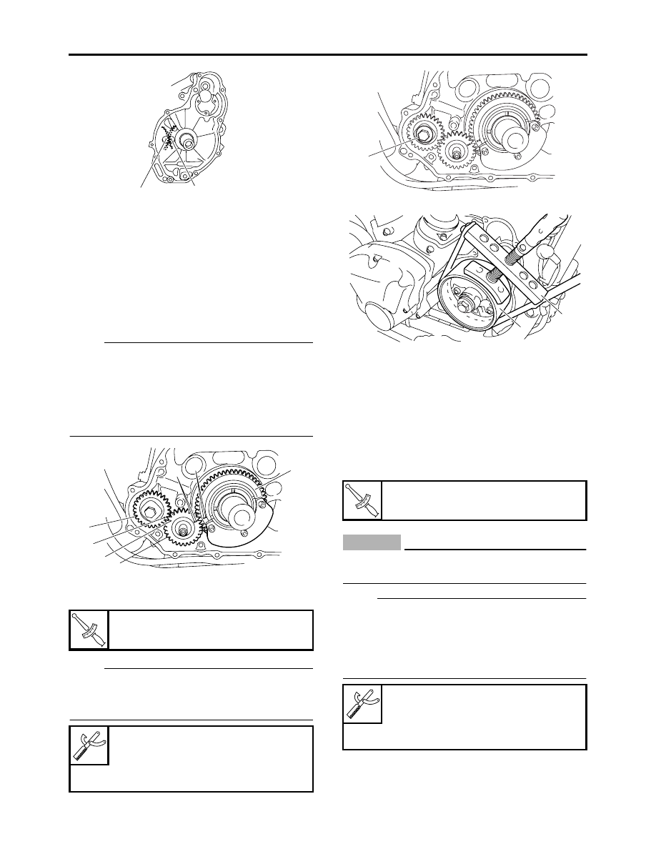
• Left balancer drive gear “1”
• Left balancer idle gear “2”
• Left balancer driven gear “3”

NOTE:

• Align the punch mark “a” on the left balancer 

drive gear with the punch mark “b” on the left 
balancer idle gear.

• Align the punch marks “c” on the left balancer 

idle gear with the punch marks “d” on the left 
balancer driven gear.

6. Tighten:

• Left balancer drive gear bolt “1”

NOTE:

While holding the generator rotor “2” with the 
sheave holder “3”, tighten the left balancer drive 
gear bolt.

EAS25230

INSTALLING THE PRIMARY DRIVE GEAR

1. Install:

• Washer
• Straight key
• Primary drive gear
• Crankshaft position sensor rotor “1”
• Spacer
• Primary drive gear bolt “2”

CAUTION:

EC1D71007

The timing marks on the crankshaft position 
sensor rotor must face outside.

NOTE:

• Lubricate the primary drive gear bolt threads 

with engine oil.

• While holding the generator rotor “3” with the 

sheave holder “4”, tighten the primary drive 
gear bolt.

T


R

.


Left balancer drive gear bolt

40 Nm (4.0 m·kg, 29 ft·lb)


Sheave holder

90890-01701

Primary clutch holder

YS-01880-A

b

a

2

d

c

1

a

b

3

T


R

.


Primary drive gear bolt

100 Nm (10.0 m·kg, 72 ft·lb)


Sheave holder

90890-01701

Primary clutch holder

YS-01880-A

1

2

3

-------------------------------------------------------------------------------------------------------------------------------------------------------------

CLUTCH

5-65

EAS25260

INSTALLING THE CLUTCH

1. Install:

• Clutch housing
• Thrust washer

NOTE:

• Lubricate the clutch housing bearings with en-

gine oil.

• Make sure that the primary driven gear teeth 

and primary drive gear teeth mesh correctly.

• Make sure that the primary driven gear teeth 

and oil pump driven gear teeth mesh correctly.

2. Install:

• Clutch boss assembly “1”

NOTE:

• Install the clutch damper spring “2” with the 

“OUTSIDE” mark facing out.

• If the wire circlip “3” has been removed, care-

fully install a new one.

3. Install:

• Clutch boss “1”

• Washer
• Conical spring washer “2”
• Clutch boss nut “3”

NOTE:

• Lubricate the clutch boss nut threads and con-

ical spring washer mating surfaces with engine 
oil.

• Install the conical spring washer “2” with the 

“OUT” mark “a” facing out.

• While holding the clutch boss with the univer-

sal clutch holder “4”, tighten the clutch boss 
nut.

• Stake the clutch boss nut “3” at a cutout “b” in 

the main axle.

4. Lubricate:

• Friction plates
• Clutch plates

(with the recommended lubricant)

5. Install:

• Friction plates 2 “1”
• Clutch plates
• Friction plate 1 “2”

NOTE:

• First, install a friction plate and then alternate 

between a clutch plate and a friction plate.

• Align a projection on each friction plate 2 “1” 

with the “

” mark “a” on the clutch housing 

and align a projection on friction plate 1 “2” with 
the punch mark “b” on the housing.

2

1

3

4

1

2

3

New

T


R

.


Clutch boss nut

105 Nm (10.5 m·kg, 75 ft·lb)


Universal clutch holder

90890-04086
YM-91042


Recommended lubricant

Engine oil

1

b

4

3

2

a

-------------------------------------------------------------------------------------------------------------------------------------------------------------

CLUTCH

5-66

6. Install:

• Clutch spring plate
• Clutch spring plate retainer

NOTE:

Tighten the clutch spring plate retainer bolts in 
stages and in a crisscross pattern.

7. Apply:

• Sealant

(onto the crankshaft position sensor lead 
grommet)

8. Install:

• Shift arm “1”

NOTE:

Install the shift arm “1” with its slot “a” aligned 
with the mark “b” in end of the shift shaft.

EAS25280

DISASSEMBLING THE CLUTCH MASTER 
CYLINDER

NOTE:

Before disassembling the clutch master cylinder, 
drain the clutch fluid from the entire clutch sys-
tem.

1. Remove:

• Clutch hose union bolt “1”
• Copper washers “2”
• Clutch hose “3”

NOTE:

To collect any remaining clutch fluid, place a 
container under the master cylinder and the end 
of the clutch hose.

ET1D71037

CHECKING THE CLUTCH MASTER 
CYLINDER

1. Check:

• Clutch master cylinder

Damage/scratches/wear 

 Replace.

• Clutch fluid delivery passage

(clutch master cylinder body)
Obstruction 

 Blow out with compressed air.

2. Check:

• Clutch master cylinder kit

Damage/scratches/wear 

 Replace.

3. Check:

• Clutch master cylinder reservoir

Cracks/damage 

 Replace.

T


R

.


Clutch spring plate retainer bolt

8 Nm (0.8 m·kg, 5.8 ft·lb)


Yamaha bond No. 1215

90890-85505
(Three Bond No.1215

®

)

T


R

.


Shift arm bolt

12 Nm (1.2 m·kg, 8.7 ft·lb)

a

b

1

2

a

b

1

b

a

1

2

3

-------------------------------------------------------------------------------------------------------------------------------------------------------------

CLUTCH

5-67

• Clutch master cylinder reservoir diaphragm

Damage/wear 

 Replace.

4. Check:

• Clutch hose

Cracks/damage/wear 

 Replace.

EAS25300

ASSEMBLING THE CLUTCH MASTER 
CYLINDER

WARNING

EW1D71010

• Before installation, all internal clutch com-

ponents must be cleaned and lubricated 
with clean or new clutch fluid.

• Never use solvents on internal clutch com-

ponents.

EAS25310

INSTALLING THE CLUTCH MASTER 
CYLINDER

1. Install:

• Clutch master cylinder “1”
• Clutch master cylinder holder “2”

NOTE:

• Align the end of the clutch lever holder with the 

punch mark “a” on the handlebar.

• First, tighten the rear bolt, then the front bolt.

2. Install:

• Copper washers 
• Clutch hose “1”
• Clutch hose union bolt “2”

WARNING

EW1D71002

Proper clutch hose routing is essential to in-
sure safe vehicle operation. Refer to “CABLE 
ROUTING” on page 2-45.

NOTE:

• Install the clutch hose at 5–25° “a” angle to the 

clutch master cylinder as shown in the illustra-
tion.

• While holding the clutch hose, tighten the 

union bolt.

• Turn the handlebar to the left and right to make 

sure the clutch hose does not touch other parts 
(e.g., wire harness, cables, leads). Correct if 
necessary.

3. Fill:

• Clutch master cylinder reservoir

(with the specified amount of the recom-
mended clutch fluid)

WARNING

EWA13370

• Use only the designated clutch fluid. Other 

clutch fluids may cause the rubber seals to 
deteriorate, causing leakage and poor 
clutch performance.

• Refill with the same type of clutch fluid that 

is already in the system. Mixing clutch flu-
ids may result in a harmful chemical reac-
tion, leading to poor clutch performance.

• When refilling, be careful that water does 

not enter the clutch fluid reservoir. Water 
will significantly lower the boiling point of 
the clutch fluid and could cause vapor lock.

CAUTION:

ECA13420

Clutch fluid may damage painted surfaces or 
plastic parts. Therefore, always clean up any 
spilt clutch fluid immediately.


Recommended clutch fluid

Brake fluid DOT 4

T


R

.


Clutch master cylinder holder 
bolt

10 Nm (1.0 m·kg, 7.2 ft·lb)

T


R

.


Clutch hose union bolt

30 Nm (3.0 m·kg, 22 ft·lb)

a

2

1

New


Recommended clutch fluid

Brake fluid DOT 4

1

2

a

-------------------------------------------------------------------------------------------------------------------------------------------------------------

CLUTCH

5-68

NOTE:

In order to ensure a correct reading of the clutch 
fluid level, make sure the top of the reservoir is 
horizontal.

4. Bleed:

• Clutch system

Refer to “BLEEDING THE HYDRAULIC 
CLUTCH SYSTEM” on page 3-15.

5. Check:

• Clutch fluid level

Below the minimum level mark “a” 

 Add the 

recommended clutch fluid to the proper level.
Refer to “CHECKING THE CLUTCH FLUID 
LEVEL” on page 3-14.

6. Check:

• Clutch lever operation

Soft or spongy feeling 

 Bleed the clutch 

system.
Refer to “BLEEDING THE HYDRAULIC 
CLUTCH SYSTEM” on page 3-15.

ET1D71004

REMOVING THE CLUTCH RELEASE 
CYLINDER

1. Remove:

• Clutch pipe union bolt “1”
• Copper washers “2”
• Clutch pipe “3”

NOTE:

Put the end of the clutch pipe into a container 
and pump out the clutch fluid carefully.

EAS25330

CHECKING THE CLUTCH RELEASE 
CYLINDER

1. Install:

• Clutch release cylinder body

Cracks/damage 

 Replace the clutch re-

lease cylinder.

2. Check:

• Clutch release cylinder “1”
• Clutch release cylinder piston “2”

Rust/scratches/wear 

 Replace the clutch 

release cylinder and clutch release cylinder 
piston as a set.

EAS25340

ASSEMBLING THE CLUTCH RELEASE 
CYLINDER

WARNING

EW1D71006

• Before installation, all internal clutch com-

ponents must be cleaned and lubricated 
with clean or new clutch fluid.

• Never use solvents on internal clutch com-

ponents as they will cause the piston seal 
to swell and distort.

• Whenever a clutch release cylinder is dis-

assembled, replace the piston seal.

3

1

2

Recommended clutch component replace-

ment schedule

Piston seal

Every two years

Clutch hose

Every four years

Clutch fluid

Every two years and 
whenever the clutch 
is disassembled


Recommended clutch fluid

Brake fluid DOT 4

1

2

-------------------------------------------------------------------------------------------------------------------------------------------------------------

CLUTCH

5-69

EAS25350

INSTALLING THE CLUTCH RELEASE 
CYLINDER

1. Install:

• Copper washers 
• Clutch pipe “1”
• Clutch pipe union bolt “2”

WARNING

EW1D71003

Proper clutch pipe routing is essential to in-
sure safe vehicle operation. Refer to “CABLE 
ROUTING” on page 2-45.

CAUTION:

EC1D71005

When installing the clutch pipe onto the 
clutch release cylinder, make sure the pipe 
“a” touches the projection “b” on the clutch 
release cylinder.

2. Fill:

• Clutch master cylinder reservoir

(with the specified amount of the recom-
mended clutch fluid)

WARNING

EWA13370

• Use only the designated clutch fluid. Other 

clutch fluids may cause the rubber seals to 
deteriorate, causing leakage and poor 
clutch performance.

• Refill with the same type of clutch fluid that 

is already in the system. Mixing clutch flu-
ids may result in a harmful chemical reac-
tion, leading to poor clutch performance.

• When refilling, be careful that water does 

not enter the clutch fluid reservoir. Water 
will significantly lower the boiling point of 
the clutch fluid and could cause vapor lock.

CAUTION:

ECA13420

Clutch fluid may damage painted surfaces or 
plastic parts. Therefore, always clean up any 
spilt clutch fluid immediately.

NOTE:

In order to ensure a correct reading of the clutch 
fluid level, make sure that the top of the reservoir 
is horizontal.

3. Bleed:

• Clutch system

Refer to “BLEEDING THE HYDRAULIC 
CLUTCH SYSTEM” on page 3-15.

4. Check:

• Clutch fluid level

Below the minimum level mark “a” 

 Add the 

recommended clutch fluid to the proper level.
Refer to “CHECKING THE CLUTCH FLUID 
LEVEL” on page 3-14.

5. Check:

• Clutch lever operation

Soft or spongy feeling 

 Bleed the clutch 

system.
Refer to “BLEEDING THE HYDRAULIC 
CLUTCH SYSTEM” on page 3-15.

T


R

.


Clutch pipe union bolt

26 Nm (2.6 m·kg, 19 ft·lb)


Recommended clutch fluid

Brake fluid DOT 4

New

2

a

1

b

-------------------------------------------------------------------------------------------------------------------------------------------------------------

SHIFT SHAFT

5-70

EAS25410

SHIFT SHAFT

Removing the shift shaft and stopper lever

Order

Job/Parts to remove

Q’ty

Remarks

Clutch housing

Refer to “CLUTCH” on page 5-50.

1

Washer

3

2

Circlip

2

3

Shift shaft

1

4

Shift shaft spring

1

5

Stopper lever

1

6

Collar

1

7

Stopper lever spring

1

8

Shift shaft spring stopper

1

For installation, reverse the removal proce-
dure.

E

8

1

2

1

4

3

6

5

7

2

1

T


R

10 Nm (1.0 m 


kg, 7.2 ft


Ib)

T


R

22 Nm (2.2 m 


kg, 16 ft


Ib)

LT

LT

LS

New

New

-------------------------------------------------------------------------------------------------------------------------------------------------------------

SHIFT SHAFT

5-71

EAS25420

CHECKING THE SHIFT SHAFT

1. Check:

• Shift shaft

Bends/damage/wear 

 Replace.

• Shift shaft spring

Damage/wear 

 Replace.

EAS25430

CHECKING THE STOPPER LEVER

1. Check:

• Stopper lever

Bends/damage 

 Replace.

Roller turns roughly 

 Replace the stopper 

lever.

• Stopper lever spring

Damage/wear 

 Replace.

EAS25450

INSTALLING THE SHIFT SHAFT

1. Install:

• Stopper lever “1”
• Collar
• Stopper lever bolt “2”
• Stopper lever spring “3”

NOTE:

• Hook the ends of the stopper lever spring onto 

the stopper lever and the crankcase boss “4”.

• Mesh the stopper lever with the shift drum seg-

ment assembly.

2. Install:

• Washers
• Circlips
• Shift shaft spring “1”
• Shift shaft “2”

NOTE:

Hook the end of the shift shaft spring onto the 
shift shaft spring stopper “3”.

T


R

.


Stopper lever bolt

10 Nm (1.0 m·kg, 7.2 ft·lb)
LOCTITE

®

2

1

3

4

2

1

3

-------------------------------------------------------------------------------------------------------------------------------------------------------------

GENERATOR AND STARTER CLUTCH

5-72

EAS24480

GENERATOR AND STARTER CLUTCH

Removing the stator coil

Order

Job/Parts to remove

Q’ty

Remarks

Engine oil

Drain.
Refer to “CHANGING THE ENGINE OIL” on 
page 3-11.

Muffler/Exhaust pipes

Refer to “ENGINE REMOVAL” on page 5-1.

Lead cover

Refer to “BELT DRIVE” on page 4-80.

Clutch pipe

Refer to “CLUTCH” on page 5-50.

1

Stator coil coupler

1

Disconnect.

2

Oil delivery pipe 2

1

3

Generator cover

1

4

Generator cover gasket

1

5

Dowel pin

2

6

Stator coil lead holder

1

7

Stator coil

1

For installation, reverse the removal proce-
dure.

(5)

LT

LT

LT

T


R

10 Nm (1.0 m 


kg, 7.2 ft


Ib)

LS

3

T


R

10 Nm (1.0 m 


kg, 7.2 ft


Ib)


R

10 Nm (1.0 m 


kg, 7.2 ft


Ib)


R

10 Nm (1.0 m 


kg, 7.2 ft


Ib)

4

5

6

2

5

New

New

New

New

7

1

T


R

10 Nm (1.0 m 


kg, 7.2 ft


Ib)

LS

T


R

10 Nm (1.0 m 


kg, 7.2 ft


Ib)

E

-------------------------------------------------------------------------------------------------------------------------------------------------------------

GENERATOR AND STARTER CLUTCH

5-73

Removing the generator rotor

Order

Job/Parts to remove

Q’ty

Remarks

1

Torque limiter

1

2

Starter clutch idle gear shaft

1

3

Starter clutch idle gear

1

4

Generator rotor

1

5

Starter clutch

1

6

Woodruff key

1

7

Starter clutch gear

1

8

Bearing

1

9

Bearing housing

1

For installation, reverse the removal proce-
dure.

E

E

R

80 Nm (8.0 m 


kg, 58 ft


Ib)

T


E

T


R

10 Nm (1.0 m 


kg, 7.2 ft


Ib)

4

6

2

3

1

5

(6)

E

7

T


R

24 Nm (2.4 m 


kg, 17 ft


Ib)

LT

LT

8

9

-------------------------------------------------------------------------------------------------------------------------------------------------------------

GENERATOR AND STARTER CLUTCH

5-74

EAS24490

REMOVING THE GENERATOR

1. Remove:

• Generator rotor bolt “1”
• Washer

NOTE:

While holding the generator rotor “2” with the 
sheave holder “3”, loosen the generator rotor 
bolt.

2. Remove:

• Generator rotor “1”

(with the rotor puller “2”)

• Woodruff key

EAS24560

REMOVING THE STARTER CLUTCH

1. Remove:

• Starter clutch bolts
• Starter clutch

NOTE:

While holding the generator rotor “1” with the 
sheave holder “2”, loosen the starter clutch 
bolts.

EAS24570

CHECKING THE STARTER CLUTCH

1. Check:

• Starter clutch rollers

Damage/wear 

 Replace.

2. Check:

• Starter clutch idle gear
• Starter clutch gear

Burrs/chips/roughness/wear 

 Replace the 

defective part(s).

3. Check:

• Starter clutch gear’s contacting surfaces

Damage/pitting/wear 

 Replace the starter 

clutch gear.

4. Check:

• Starter clutch operation

▼▼▼

▼ ▼▼▼

▼ ▼▼▼

▼ ▼▼▼

▼ ▼▼▼

▼ ▼▼▼

▼▼▼

a. Install the starter clutch gear “1” onto the 

starter clutch and hold the generator rotor “2”.

b. When turning the starter clutch gear clock-

wise “A”, the starter clutch and the starter 
clutch gear should engage, otherwise the 
starter clutch is faulty and must be replaced.

c. When turning the starter clutch gear counter-

clockwise “B”, it should turn freely, otherwise 
the starter clutch is faulty and must be re-
placed.


Sheave holder

90890-01701

Primary clutch holder

YS-01880-A


Rotor puller

90890-01080

Stator rotor puller

YM-01080-A

1

2

3

1

2


Sheave holder

90890-01701

Primary clutch holder

YS-01880-A

2

1

-------------------------------------------------------------------------------------------------------------------------------------------------------------

GENERATOR AND STARTER CLUTCH

5-75

▲▲▲

▲ ▲▲▲

▲ ▲▲▲

▲ ▲▲▲

▲ ▲▲▲

▲ ▲▲▲

▲▲▲

ET1D71020

CHECKING THE TORQUE LIMITER

1. Check:

• Torque limiter

Damage/wear 

 Replace.

NOTE:

Do not disassemble the torque limiter.

EAS24600

INSTALLING THE STARTER CLUTCH

1. Install:

• Starter clutch

NOTE:

While holding the generator rotor “1” with the 
sheave holder “2”, tighten the starter clutch 
bolts.

EAS24510

INSTALLING THE GENERATOR

1. Install:

• Woodruff key

• Generator rotor “1”
• Washer
• Generator rotor bolt “2”

NOTE:

• Clean the tapered portion of the generator 

shaft and the generator rotor hub.

• When installing the rotor, make sure the woo-

druff key is properly seated in the key way of 
the generator shaft.

• Lubricate the generator rotor bolt threads and 

washer mating surfaces with engine oil.

2. Tighten:

• Generator rotor bolt “1”

NOTE:

While holding the generator rotor “2” with a 
sheave holder “3”, tighten the generator rotor 
bolt.

3. Apply:

• Sealant

(onto the stator coil lead grommet)

T


R

.


Starter clutch bolt

24 Nm (2.4 m·kg, 17 ft·lb)
LOCTITE

®


Sheave holder

90890-01701

Primary clutch holder

YS-01880-A

2

1

T


R

.


Generator rotor bolt

80 Nm (8.0 m·kg, 58 ft·lb)


Sheave holder

90890-01701

Primary clutch holder

YS-01880-A

1

2

1

2

3

-------------------------------------------------------------------------------------------------------------------------------------------------------------

GENERATOR AND STARTER CLUTCH

5-76


Yamaha bond No. 1215

90890-85505
(Three Bond No.1215

®

)

-------------------------------------------------------------------------------------------------------------------------------------------------------------

ELECTRIC STARTER

5-77

EAS24780

ELECTRIC STARTER

Removing the starter motor

Order

Job/Parts to remove

Q’ty

Remarks

1

Starter motor lead

1

Disconnect.

2

Starter motor

1

For installation, reverse the removal proce-
dure.

2

1

T


R

10 Nm (1.0 m 


kg, 7.2 ft


Ib)

-------------------------------------------------------------------------------------------------------------------------------------------------------------

ELECTRIC STARTER

5-78

Disassembling the starter motor

Order

Job/Parts to remove

Q’ty

Remarks

1

Starter motor front cover

1

2

Bearing

1

3

Oil seal

1

4

Circlip

1

5

Starter motor rear cover

1

6

Brush

2

7

Brush holder (along with the brushes)

1

8

Brush seat (along with the brushes)

1

9

Bearing

1

10

Gasket

2

11

Armature assembly

1

12

Starter motor yoke

1

For assembly, reverse the disassembly pro-
cedure.

6

2

3

5

7

1

4

LS

New

New

New

New

New

New

10

9

10

8

12

11

LS

-------------------------------------------------------------------------------------------------------------------------------------------------------------

ELECTRIC STARTER

5-79

EAS24790

CHECKING THE STARTER MOTOR

1. Check:

• Commutator

Dirt 

 Clean with 600 grit sandpaper.

2. Measure:

• Commutator diameter “a”

Out of specification 

 Replace the starter 

motor.

3. Measure:

• Mica undercut “a”

Out of specification 

 Scrape the mica to the 

proper measurement with a hacksaw blade 
that has been grounded to fit the commutator.

NOTE:

The mica of the commutator must be undercut to 
ensure proper operation of the commutator.

4. Measure:

• Armature assembly resistances (commutator 

and insulation)
Out of specification 

 Replace the starter 

motor.

▼▼▼

▼ ▼▼▼

▼ ▼▼▼

▼ ▼▼▼

▼ ▼▼▼

▼ ▼▼▼

▼▼▼

a. Measure the armature assembly resistances 

with the pocket tester.

b. If any resistance is out of specification, re-

place the starter motor.

▲▲▲

▲ ▲▲▲

▲ ▲▲▲

▲ ▲▲▲

▲ ▲▲▲

▲ ▲▲▲

▲▲▲

5. Measure:

• Brush length “a”

Out of specification 

 Replace the brushes 

as a set.

6. Measure:

• Brush spring force

Out of specification 

 Replace the brush 

springs as a set.


Limit

27.5 mm (1.08 in)


Mica undercut (depth)

1.50 mm (0.06 in)


Pocket tester

90890-03112

Analog pocket tester

YU-03112-C


Armature coil

Commutator resistance “1”

0.0081–0.0099 

 at 20 °C (68 °F)

Insulation resistance “2”

Above 1 M

 at 20 °C (68 °F)


Limit

5.00 mm (0.20 in)


Brush spring force

7.36–11.04 N (26.49–39.74 oz) 
(750–1126 gf)

-------------------------------------------------------------------------------------------------------------------------------------------------------------


Content      ..     16      17      18      19     ..