Yamaha YFM45FAR, YFM450FAR. Service Manual - part 21
 

  Index      Manuals     Yamaha YFM45FAR, YFM450FAR. Service Manual


Search            copyright infringement  


Content      ..     19      20      21      22     ..


Yamaha YFM45FAR, YFM450FAR. Service Manual - part 21


8 - 42

CHAS

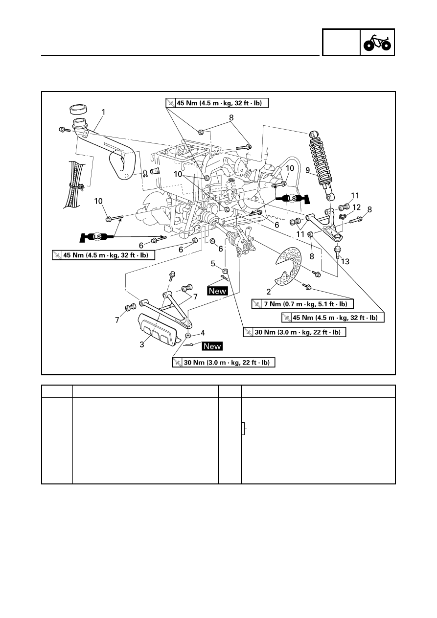
FRONT ARMS AND FRONT SHOCK ABSORBER

FRONT ARMS AND FRONT SHOCK ABSORBER

Order

Job name/Part name

Q’ty

Remarks

Removing the front arms and front 
shock absorber

Remove the parts in the order below.

Engine skid plate

Refer to “SEAT, CARRIERS, FENDERS 
AND FUEL TANK” in CHAPTER 3.

Front fender
Front wheel/brake disc

Refer to “FRONT AND REAR WHEELS”.

1

Air  duct

1

2

Brake disc guard

1

3

Protector

1

8 - 43

CHAS

FRONT ARMS AND FRONT SHOCK ABSORBER

Order

Job name/Part name

Q’ty

Remarks

4

Nut

1

Refer to “REMOVING THE FRONT 
ARMS” and “INSTALLING THE FRONT 
ARMS AND FRONT SHOCK 
ABSORBER”.

5

Nut

1

6

Bolt/nut

2/2

7

Front lower arm/bushing

1/2

8

Nut/bolt

2/2

9

Front shock absorber

1

10

Bolt/nut

2/2

11

Front upper arm/bushing

1/2

12

Circlip

1

13

Ball joint

1

For installation, reverse the removal 
procedure. 

8 - 44

CHAS

FRONT ARMS AND FRONT SHOCK ABSORBER

REMOVING THE FRONT ARMS 

1.Check:

Front arm free play

*****************************************************

Checking steps:

Check the front arm side play 

È

 by moving it

from side to side.
If side play is noticeable, check the bushings.

Check the front arm vertical movement 

É

 by

moving it up and down.
If the vertical movement is tight or rough, or if
there is binding, check the bushings.

*****************************************************
2.Remove:

Front arms

CHECKING THE FRONT ARM

1.Check:

Front arms
Bends/damage 

 Replace.

2.Check:

Bushings
Wear/damage 

 Replace.

3.Check:

Ball joint
Damage/pitting 

 Replace the ball joint.

Free play 

 Replace the ball joint.

Turns roughly 

 Replace the ball joint.

8 - 45

CHAS

*****************************************************

Replacement steps:

Clean the outside of the front lower arm.

Remove the circlip 

1

 and rubber boot 

2

.

Use the ball joint remover and installer set.

Install the body 

3

, long bolt 

4

, remover

washer 

5

 and remover spacer 

6

 onto ball

joint.

NOTE:

Remover washer 

5

 must be aligned with the

projection on the head of the ball joint.

Hold the body 

3

 in place while turning in the

long bolt 

4

 to remove the ball joint 

0

 from

the front lower arm.

Remove the ball joint remover/installer.

Ball joint remover/installer set:

P/N. YM-01474/90890-01474

Ball joint remover/installer 
attachment set:

P/N. YM-01477

3

Body

YM-01474
90890-01474

4

Long bolt

YM-01474
90890-01474

5

Remover washer

YM-01477

6

Remover spacer

YM-01477

7

Installer attachment

YM-01477

8

Installer spacer

YM-01477

9

Installer guide

YM-01477

Install the long bolt 

4

, installer spacer 

8

and installer guide 

9

 onto the body 

3

.

FRONT ARMS AND FRONT SHOCK ABSORBER

8 - 46

CHAS

FRONT ARMS AND FRONT SHOCK ABSORBER

Attach the assembled ball joint remover/
installer, new ball joint 

A

 and installer

attachment 

7

 to the front lower arm 

B

.

NOTE:

Do not tap or damage the top of the ball joint.

Hold the body 

3

 in place while turning in the

long bolt 

4

 to install the new ball joint 

A

 into

the front lower arm 

B

.

Remove the ball joint remover/installer.

Apply lithium-soap base grease to the new
ball joint 

A

.

Install a new rubber boot and new circlip.

NOTE:

Always use a new ball joint set.

*****************************************************

CHECKING THE FRONT SHOCK 
ABSORBER

1.Check:

Shock absorber rod
Bends/damage 

 Replace the shock

absorber assembly.

Shock absorber assembly
Oil leaks 

 Replace the shock absorber

assembly.

Spring
Fatigue 

 Replace the shock absorber

assembly.
Move the spring up and down.

8 - 47

CHAS

FRONT ARMS AND FRONT SHOCK ABSORBER

INSTALLING THE FRONT ARMS AND 
FRONT SHOCK ABSORBER

1.Install:

Front arms

Front shock absorber

*****************************************************

Installation steps:

Install the front upper arm 

1

 and front lower

arm 

2

.

NOTE:

Lubricate the bolts 

3

 with lithium-soap-

based grease.

Be sure to position the bolts 

3

 so that the

bolt head faces outward.

Temporarily tighten the nuts 

4

.

Install the front shock absorber 

5

.

Install the ball joints.

Install the new cotter pins.

Tighten the nuts 

4

.

NOTE:

Before tightening the nuts 

4

, adjust the length

a

 to 310 mm (12.2 in).

*****************************************************

T


R

.

.

Nut 

6

:

45 Nm (4.5 m • kg, 32 ft • lb)

T


R

.

.

Nut 

7

:

30 Nm (3.0 m • kg, 22 ft • lb)

T


R

.

.

Nut 

4

:

45 Nm (4.5 m • kg, 32 ft • lb)

8 - 48

CHAS

REAR SHOCK ABSORBER AND SWINGARM

REAR SHOCK ABSORBER AND SWINGARM

Order

Job name/Part name

Q’ty

Remarks

Removing the rear shock absorber 
and swingarm

Remove the parts in the order below.

Rear wheel hubs/brake disc

Refer to “FRONT AND REAR WHEELS”.

Rear brake caliper/brake hose

Refer to “FRONT AND REAR BRAKES”.

Final drive gear assembly

Refer to “REAR AXLE/FINAL DRIVE GEAR 
AND DRIVE SHAFT” in CHAPTER 7.

1

Clip/washer/pin

1/1/1

2

Nut/bolt

1/1

3

Rear shock absorber

1

4

Collar

1

5

Trailer hitch bracket

1

6

Final drive gear case breather hose

1

7

Metal clamp

1

8 - 49

CHAS

REAR SHOCK ABSORBER AND SWINGARM

Order

Job name/Part name

Q’ty

Remarks

8

Rear axle housing

1

Refer to “INSTALLING THE REAR AXLE 
HOUSING”.

9

Nut/bolt

2/2

Refer to “REMOVING THE 
SWINGARM”.

10

Swingarm/bushing

1/2

11

Spring/rubber boot

1/1

For installation, reverse the removal 
procedure.

8 - 50

CHAS

REAR SHOCK ABSORBER AND SWINGARM

REMOVING THE SWINGARM 

1.Check: 

Swingarm free play

*****************************************************

Checking steps: 

Check the tightening torque of the nuts
(swingarm).

Check the swingarm side play 

È

 by moving

it from side to side.
If side play is noticeable, check the bushing
and frame pivot.

Check the swingarm vertical movement 

É

by moving it up and down.
If vertical movement is tight or rough, or if
there is binding, check the bushing and
frame pivot.

*****************************************************
2.Remove: 

Nuts

Bolts

Swingarm

T


R

.

.

Nut (swingarm):

82 Nm (8.2 m • kg, 59 ft • lb)

CHECKING THE REAR SHOCK ABSORBER

1.Check:

Shock absorber
Oil leaks 

 Replace the shock absorber

assembly.

Shock absorber rod
Bends/damage 

 Replace the shock

absorber assembly.

Spring
Fatigue 

 Replace the shock absorber

assembly.
Move the spring up and down.

8 - 51

CHAS

REAR SHOCK ABSORBER AND SWINGARM

CHECKING THE SWINGARM

1.Check: 

Swingarm 

1


Rear axle housing 

2


Bends/cracks/damage 

 Replace.

2.Check:

Bushings 

1


Wear/damage 

 Replace. 

CHECKING THE RUBBER BOOT

1.Check:

Rubber boot 

1


Damage 

 Replace.

INSTALLING THE RUBBER BOOT

1.Apply:

Adhesive (for rubber)
(to the engine 

1

)

2.Install:

Rubber boot 

2


NOTE:

Be sure to position the rubber boot so that the
tang 

3

 faces towards the left.

8 - 52

CHAS

REAR SHOCK ABSORBER AND SWINGARM

INSTALLING THE REAR AXLE HOUSING

1.Install:

Rear axle housing

Final gear case assembly

Rear axle
(with dust seal)

*****************************************************

Installation steps:

Install the drive shaft.
Refer to “REAR AXLE/FINAL DRIVE GEAR
AND DRIVE SHAFT” in CHAPTER 7.

Apply sealant (Quick Gasket

®

) to the mating

surfaces of the swingarm and the final gear
case.

Temporarily install the rear axle housing 

1

and final gear case assembly 

2

 on the

swingarm. The bolts and nuts 

3

 ~ 

5

 should

be temporarily tightened.

Install the rear axle (with dust seal) 

6

 from

the left side of the machine.
Refer to “REAR AXLE/FINAL DRIVE GEAR
AND DRIVE SHAFT” in CHAPTER 7.

Tighten the bolts and nuts 

3

 ~ 

5

 in the

specified order.

3

Nut (

×

4)

4

Bolt (

×

4)

5

Bolt/nut (

×

4)

*****************************************************

T


R

.

.

Nut 

3

:

63 Nm (6.3 m • kg, 45 ft • lb)
LOCTITE

®


Bolt 

4

:

63 Nm (6.3 m • kg, 45 ft • lb)
LOCTITE

®


Nut 

5

:

63 Nm (6.3 m • kg, 45 ft • lb)

+

ELEC

CHAPTER 9.

ELECTRICAL

ELECTRICAL COMPONENTS 

..................................................................... 9-1

CHECKING THE SWITCH 

............................................................................ 9-2

CHECKING THE SWITCH  .................................................................... 9-2
CHECKING A SWITCH SHOWN IN THE MANUAL  ............................. 9-2
CHECKING THE SWITCH CONTINUITY  ............................................. 9-4

CHECKING THE BULBS AND BULB SOCKETS 

....................................... 9-6

TYPES OF BULBS ................................................................................ 9-6
CHECKING THE CONDITION OF THE BULBS  ................................... 9-6
CHECKING THE CONDITION OF THE BULB SOCKETS  ................... 9-8

IGNITION SYSTEM 

...................................................................................... 9-9

CIRCUIT DIAGRAM  .............................................................................. 9-9
TROUBLESHOOTING ........................................................................ 9-10

ELECTRIC STARTING SYSTEM 

............................................................... 9-15

CIRCUIT DIAGRAM  ............................................................................ 9-15
TROUBLESHOOTING ........................................................................ 9-16
STARTER MOTOR  ............................................................................. 9-19
CHECKING THE STARTER MOTOR  ................................................. 9-20
ASSEMBLING THE STARTER MOTOR ............................................. 9-21

CHARGING SYSTEM 

................................................................................. 9-22

CIRCUIT DIAGRAM  ............................................................................ 9-22
TROUBLESHOOTING ........................................................................ 9-23

LIGHTING SYSTEM 

................................................................................... 9-25

CIRCUIT DIAGRAM  ............................................................................ 9-25
TROUBLESHOOTING ........................................................................ 9-26
CHECKING THE LIGHTING SYSTEM  ............................................... 9-28

SIGNAL SYSTEM 

....................................................................................... 9-30

CIRCUIT DIAGRAM  ............................................................................ 9-30
TROUBLESHOOTING ........................................................................ 9-32
CHECKING THE SIGNAL SYSTEM  ................................................... 9-34

COOLING SYSTEM 

.................................................................................... 9-38

CIRCUIT DIAGRAM  ............................................................................ 9-38
TROUBLESHOOTING   ....................................................................... 9-39

2WD/4WD SELECTING SYSTEM 

.............................................................. 9-43

CIRCUIT DIAGRAM  ............................................................................ 9-43
TROUBLESHOOTING ........................................................................ 9-44

9 - 1

+

ELEC

ELECTRICAL COMPONENTS

EB800000

ELECTRICAL

ELECTRICAL COMPONENTS

1

Main switch

2

Front brake light 
switch

3

Rear brake switch

4

Thermo switch 1

5

Battery

6

Tail/brake light

7

Fuse box

8

Four-wheel drive 
relay 2

9

Four-wheel drive 
relay 1

0

Main fuse

A

Starter relay

B

CDI unit

C

Rectifier/regulator

D

Reverse switch

E

Neutral switch

F

High-range switch

G

Low-range switch

H

Speed sensor

I

Rear brake light switch

J

Gear motor

K

Thermo switch 2

L

Fan

M

Headlight

N

Circuit breaker (fan)

O

Four-wheel drive relay 3

P

Ignition coil

1

2

3

4

5

6

7

8

9

0

A

B

C

G

F

E

D

H

I

J

K

L

M

N

O

P

9 - 2

+

ELEC

CHECKING THE SWITCH

CHECKING THE SWITCH

CHECKING THE SWITCH

Use a pocket tester to check the terminals for
continuity. If the continuity is faulty at any
point, replace the switch.

NOTE:

Set the pocket tester to “0” before starting
the test.

The pocket tester should be set to the


Ω ×

 1”

range when testing the switch for continuity.

Turn the switch on and off a few times when
checking it.

Pocket tester: 

P/N. YU-03112, 90890-03112

CHECKING A SWITCH SHOWN IN THE 
MANUAL

The terminal connections for switches (main
switch, handlebar switch, engine stop switch,
light switch, etc.) are shown in a chart similar
to the one on the left.
This chart shows the switch positions in the
column and the switch lead colors in the top
row.
For each switch position, “

” indicates

the terminals with continuity.

The example chart shows that:

There is continuity between red and brown/
blue, and between red and brown when the
switch is set to “ON”.

Br

/

L

Br

R

R

R

R

Br

Br

/

L

ON

OFF

9 - 3

+

ELEC

CHECKING THE SWITCH

9 - 4

+

ELEC

CHECKING THE SWITCH

CHECKING THE SWITCH CONTINUITY

Refer to “CHECKING THE SWITCH” and check for continuity between lead terminals.
Poor connection, no continuity 

 Correct or replace.

*

 The coupler locations are circled.

L

B

Y

G

Br

L

/

B

(BLACK)

1

4

5

D

6

2

3

R

/

B R

/

W

PUSH

Br L Y G

B

R

/

W

L

/

B L

/

G

Br

/

L Br

R

L

/

R Sb Br Gy G

/

R B

R

/

B

L

/

B

2WD

4WD

LOCK

L

/

G

L

/

B

L

/

R

Sb

Gy

Br

G

/

R

B

(BLACK)

(GRAY)

ON

OFF

R

Br

Br

/

L

Br

B

P

P Br

B

B

(BLACK)

7

B

B

(BLACK)

8

9

C

B

B

B

A

0

Br

/

L

Br

R

R

ON

OFF

R

R

Br

Br

/

L

PUSH

OFF


Content      ..     19      20      21      22     ..