Yamaha YFM45FAR, YFM450FAR. Service Manual - part 19
 

  Index      Manuals     Yamaha YFM45FAR, YFM450FAR. Service Manual


Search            copyright infringement  


Content      ..     17      18      19      20     ..


Yamaha YFM45FAR, YFM450FAR. Service Manual - part 19


8 - 10

CHAS

FRONT AND REAR BRAKES

REPLACING THE REAR BRAKE PAD

NOTE:

It is not necessary to disassemble the brake
caliper and brake hose to replace the brake
pads.

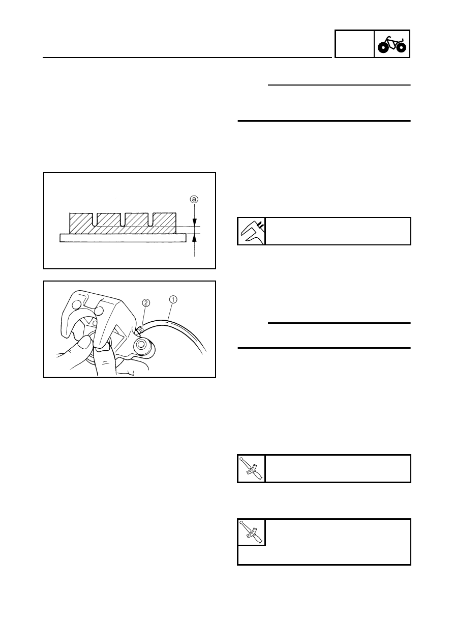
1.Measure:

Brake pad wear limit 

a


Out of specification 

 Replace the brake

pad as a set.

Brake pad wear limit:

1 mm (0.04 in)

2.Install:

Brake pads

Brake pad spring

NOTE:

Always install new brake pads, brake pad
shims, insulator and brake pad spring as a set.

*****************************************************

Installation steps:

Connect a suitable hose 

1

 tightly to the

brake caliper bleed screw 

2

. Put the other

end of this hose into an open container.

Loosen the brake caliper bleed screw and,
using a finger, push the caliper piston into
the brake caliper.

Tighten the brake caliper bleed screw.

Install new brake pads, new insulator, new
pad shims and a new brake pad spring.

Install the holding bolts and brake caliper.

*****************************************************

T


R

.

.

Brake caliper bleed screw:

6 Nm (0.6 m • kg, 4.3 ft • lb)

T


R

.

.

Brake pad holding bolt:

18 Nm (1.8 m • kg, 13 ft • lb)

Brake caliper mounting bolt:

30 Nm (3.0 m • kg, 22 ft • lb)

8 - 11

CHAS

FRONT AND REAR BRAKES

3.Check:

Brake fluid level
Refer to “CHECKING THE BRAKE FLUID
LEVEL” in CHAPTER 3.

4.Check:

Brake lever or brake pedal operation
Soft or spongy feeling 

 Bleed the rear

brake system.
Refer to “BLEEDING THE HYDRAULIC
BRAKE SYSTEM” in CHAPTER 3.

8 - 12

CHAS

FRONT AND REAR BRAKES

FRONT BRAKE MASTER CYLINDER

Order

Job name/Part name

Q’ty

Remarks

Removing the front brake master 
cylinder 

Remove the parts in the order below.

Brake fluid

Drain.

On-command four-wheel drive switch 
and differential gear lock switch

Refer to “HANDLEBAR”.

1

Brake fluid reservoir cap

1

2

Brake fluid reservoir diaphragm

1

3

Brake  lever

1

4

Union bolt

1

Refer to “INSTALLING THE FRONT 
BRAKE MASTER CYLINDER”.

5

Copper washer

2

6

Brake hose

1

7

Front brake light switch

1

8

Brake master cylinder bracket

1

9

Brake master cylinder

1

For installation, reverse the removal 
procedure. 

8 - 13

CHAS

FRONT AND REAR BRAKES

Order

Job name/Part name

Q’ty

Remarks

Disassembling the front brake 
master cylinder

Remove the parts in the order below.

1


Brake master cylinder kit

1

Refer to “ASSEMBLING THE FRONT 
BRAKE MASTER CYLINDER”.

2


Brake master cylinder

1

For assembly, reverse the disassembly 
procedure.

8 - 14

CHAS

FRONT AND REAR BRAKES

REAR BRAKE MASTER CYLINDER

Order

Job name/Part name

Q’ty

Remarks

Removing the rear brake master 
cylinder

Remove the parts in the order below.

Front fender 

Refer to “SEAT, CARRIERS, FENDERS 
AND FUEL TANK” in CHAPTER 3.

Brake fluid

Drain.

1

Brake fluid reservoir cap

1

2

Brake fluid reservoir diaphragm holder

1

3

Brake fluid reservoir diaphragm

1

4

Brake fluid reservoir

1

5

Brake master cylinder cover

1

6

Brake fluid reservoir hose

1

7

Union bolt

1

Refer to “INSTALLING THE REAR 
BRAKE MASTER CYLINDER”.

8

Copper washer

2

9

Brake hose

1

8 - 15

CHAS

FRONT AND REAR BRAKES

Order

Job name/Part name

Q’ty

Remarks

10

Brake cable

1

Disconnect.

11

Bracket

1

12

Brake master cylinder

1

13

Hose joint

1

14

Brake pedal

1

15

Select lever control cable

1

Disconnect.

16

Rear brake light switch

1

17

Bracket

1

18

Bracket

1

19

Brake master cylinder bracket

1

For installation, reverse the removal 
procedure.

8 - 16

CHAS

FRONT AND REAR BRAKES

Order

Job name/Part name

Q’ty

Remarks

Disassembling the rear brake 
master cylinder

Remove the parts in the order below.

1

Brake master cylinder kit

1

Refer to “ASSEMBLING THE REAR 
BRAKE MASTER CYLINDER”.

2

Brake master cylinder

1

For assembly, reverse the disassembly 
procedure.

8 - 17

CHAS

FRONT AND REAR BRAKES

CHECKING THE MASTER CYLINDER

1.Check:

Brake master cylinder 

1


Wear/scratches 

 Replace the brake master

cylinder assembly.

Brake master cylinder body
Cracks/damage 

 Replace.

Brake fluid delivery passage
(brake master cylinder body)
Blockage 

 Blow out with compressed air.

È

Front

É

Rear

È

É

2.Check:

Front brake master cylinder reservoir 

1


Front brake master cylinder reservoir
diaphragm 

2


Cracks/damage 

 Replace.

3.Check:

Rear brake fluid reservoir 

1


Rear brake fluid reservoir diaphragm 

2


Cracks/damage 

 Replace.

8 - 18

CHAS

FRONT AND REAR BRAKES

EB702060

ASSEMBLING THE FRONT BRAKE 
MASTER CYLINDER

WARNING

All internal brake components should be
cleaned and lubricated with new brake
fluid only before installation.

Whenever a master cylinder is
disassembled, replace the piston seals
and dust seals.

Recommended brake fluid:

DOT 4

EB702060

ASSEMBLING THE REAR BRAKE MASTER 
CYLINDER

WARNING

All internal brake components should be
cleaned and lubricated with new brake
fluid only before installation.

Whenever a master cylinder is
disassembled, replace the piston seals
and dust seals.

1.Install:

Brake master cylinder kit

Nut 

1


Joint 

2


NOTE:

Turn the adjusting bolt 

3

 until the clearance 

a

is within the specified limits when install the
joint 

2

.

2.Tighten:

Nut 

1


Recommended brake fluid:

DOT 4

Clearance 

a

:

4 ~ 6 mm (0.16 ~ 0.24 in)

8 - 19

CHAS

FRONT AND REAR BRAKES

INSTALLING THE FRONT BRAKE MASTER 
CYLINDER 

1.Install:

Brake master cylinder 

1


Brake master cylinder bracket 

2


NOTE:

The  “UP” mark on the brake master cylinder
bracket 

2

 should face up.

2.Install:

Copper washers

Brake hose 

Union bolt 

NOTE:

Tighten the union bolt while holding the
brake hose as shown.

Turn the handlebar to the left and to the right
to check that the brake hose does not touch
other parts (throttle cable, wire harness,
leads, etc.). Correct if necessary.

WARNING

Proper brake hose routing is essential to
insure safe machine operation. Refer to
“CABLE ROUTING” in CHAPTER 2.

3.Fill:

Brake fluid reservoir

CAUTION:

Brake fluid may damage painted surfaces
or plastic parts. Always clean up spilled
brake fluid immediately.

WARNING

Use only the designated quality brake
fluid: other brake fluids may deteriorate
the rubber seals, causing leakage and
poor brake performance.

Refill with the same type of brake fluid:
mixing brake fluids may result in a
harmful chemical reaction and lead to
poor brake performance.

Recommended brake fluid:

DOT 4

T


R

.

.

7 Nm (0.7 m • kg, 5.1 ft • lb)

60˚

New

T


R

.

.

27 Nm (2.7 m • kg, 19 ft • lb)

8 - 20

CHAS

FRONT AND REAR BRAKES

Be careful that water does not enter the
brake master cylinder when refilling.
Water will significantly lower the boiling
point of the brake fluid and may result in
vapor lock.

4.Air bleed:

Brake system
Refer to “BLEEDING THE HYDRAULIC
BRAKE SYSTEM” in CHAPTER 3.

5.Check:

Brake fluid level
Brake fluid level is under the “LOWER” level
line 

 Fill up.

Refer to “CHECKING THE BRAKE FLUID
LEVEL” in CHAPTER 3.

INSTALLING THE REAR BRAKE MASTER 
CYLINDER

1.Install:

Copper washers 

1

Brake hose 

2


Union bolt 

3

CAUTION:

When installing the brake hose onto the
brake master cylinder, make sure the brake
pipe touches the projection 

a

 as shown.

WARNING

Proper brake hose routing is essential to
insure safe machine operation. Refer to
“CABLE ROUTING” in CHAPTER 2.

New

T


R

.

.

30 Nm (3.0 m • kg, 22 ft • lb)

8 - 21

CHAS

FRONT AND REAR BRAKES

2.Fill:

Brake fluid reservoir

CAUTION:

Brake fluid may damage painted surfaces
or plastic parts. Always clean up spilled
brake fluid immediately.

WARNING

Use only the designated quality brake
fluid: other brake fluids may deteriorate
the rubber seals, causing leakage and
poor brake performance.

Refill with the same type of brake fluid:
mixing brake fluids may result in a
harmful chemical reaction and lead to
poor brake performance.

Be careful that water does not enter the
brake master cylinder when refilling.
Water will significantly lower the boiling
point of the brake fluid and may result in
vapor lock.

Recommended brake fluid:

DOT 4

3.Air bleed:

Brake system
Refer to “BLEEDING THE HYDRAULIC
BRAKE SYSTEM” in CHAPTER 3.

4.Check:

Brake fluid level
Brake fluid level is under the “LOWER” level
line 

 Fill up.

Refer to “CHECKING THE BRAKE FLUID
LEVEL” in CHAPTER 3.

8 - 22

CHAS

FRONT AND REAR BRAKES

FRONT BRAKE CALIPER

Order

Job name/Part name

Q’ty

Remarks

Removing the front brake caliper

Remove the parts in the order below.

Brake fluid

Drain.

Front wheel

Refer to “FRONT AND REAR WHEELS”.

1

Union bolt

1

Refer to “INSTALLING 
THE FRONT BRAKE 
CALIPER”.

2

Copper washer

2

3

Brake hose

1

Disconnect.

4

Cap/retaining bolt

1/1

Loosen.

5

Brake pad holding bolt

2

Loosen.

6

Brake caliper mounting bolt

2

7

Brake caliper assembly

1

For installation, reverse the removal 
procedure. 

8 - 23

CHAS

FRONT AND REAR BRAKES

Order

Job name/Part name

Q’ty

Remarks

Disassembling the front brake 
caliper

Remove the parts in the order below.

1


Brake pad holding bolt

2

2


Brake pad/pad shim

2/1

3

 Pad 

spring

1

4

 Retaining 

bolt

1

5

 Caliper 

bracket

1

6


Brake caliper piston

1

Refer to “DISASSEMBLING/
ASSEMBLING THE FRONT AND REAR 
BRAKE CALIPER”.

7

 Dust 

seal

1

8


Caliper piston seal

1

9

 Bleed 

screw

1

For assembly, reverse the disassembly 
procedure.

8 - 24

CHAS

FRONT AND REAR BRAKES

REAR BRAKE CALIPER

Order

Job name/Part name

Q’ty

Remarks

Removing the rear brake caliper

Remove the parts in the order below.

Brake fluid

Drain.

Rear wheel

Refer to “FRONT AND REAR WHEELS”.

1

Union bolt

1

Refer to “INSTALLING 
THE REAR BRAKE 
CALIPER”.

2

Copper washer

2

3

Brake hose

1

Disconnect.

4

Brake pad holding bolt

2

Loosen.

5

Brake caliper mounting bolt

2

6

Brake caliper assembly

1

For installation, reverse the removal 
procedure. 

8 - 25

CHAS

FRONT AND REAR BRAKES

Order

Job name/Part name

Q’ty

Remarks

Disassembling the rear brake caliper

Remove the parts in the order below.

1


Brake pad holding bolt

2

2


Brake pad/insulator/pad shim

2/2/2

3

 Pad 

spring

1

4

 Caliper 

bracket

1

5


Brake caliper piston

1

Refer to “DISASSEMBLING/
ASSEMBLING THE FRONT AND REAR 
BRAKE CALIPER”.

6

 Dust 

seal

1

7


Caliper piston seal

1

8

 Bleed 

screw

1

For assembly, reverse the disassembly 
procedure.


Content      ..     17      18      19      20     ..