ATV Arctic Cat 2002. Service Manual - part 7
 

  Index      Manuals     ATV Arctic Cat 2002. Service Manual


Search            copyright infringement  


Content      ..     5      6      7      8     ..


ATV Arctic Cat 2002. Service Manual - part 7


49

3

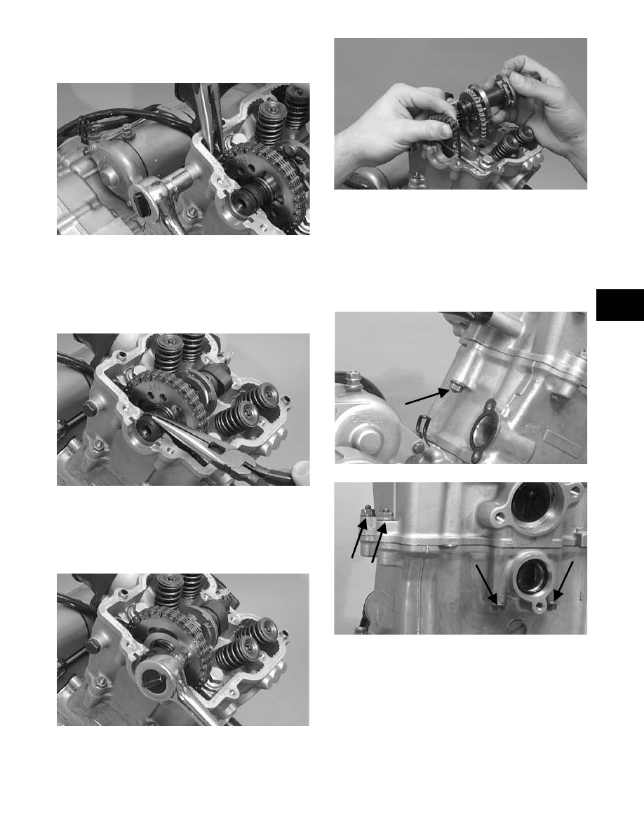
4. Remove the cap screw securing the chain

tensioner (account for a washer); then remove the

tensioner.

74)

5. Using an awl, rotate the C-ring in its groove until

it is out of the cylinder head; then remove the

C-ring.

„

         ! 

$

7)

6. Bend the washer tabs and remove the two cap

screws securing the sprocket to the camshaft; then

drop the sprocket off the camshaft. While holding

the chain, slide the sprocket and camshaft out of

the cylinder head.

7)

66)

„

  (!   "  & 

!

$

7. Remove the five nuts securing the cylinder head to

the cylinder; then remove the four cylinder head

cap screws with copper washers (note location of

the different-sized cap screws and nuts).

78)

7?)

RepairPro Service Manual

-------------------------------------------------------------------------------------------------------------------------------------------------------------

57

76)

8. Remove the cylinder head from the cylinder,

remove the gasket, and account for two alignment

pins.

77)

9. Remove the cam chain guide.

7)

C. Cylinder
D. Piston

„

  %! 9   !  

!!$

10. Loosen the clamp securing the coolant hose to the

union; then detach the hose.

11. Remove the two nuts securing the cylinder to the

crankcase.

7)

12. Lift the cylinder off the crankcase taking care not

to allow the piston to drop against the crankcase.

Account for the gasket and two alignment pins.

74)

75)

 AT THIS POINT

 " ""  &  

%"!%! $

 AT THIS POINT

 !     %"

!%! $

-------------------------------------------------------------------------------------------------------------------------------------------------------------

5

3

76)

13. Using an awl, remove one piston-pin circlip.

7)

14. Using the Piston-Pin Puller (p/n 0644-328),

remove the piston pin. Account for the

opposite-side circlip. Remove the piston.

„

  ,  "   "  !!

!!!$

7)

„

  %!!      

 "

1.<!#7444776=$

„

 ,A !

!!$B!

!!&$,!

 ""C$

'7?5

A. Starting with the top ring, slide one end of the

ring out of the ring-groove.

B. Remove each ring by working it toward the

dome of the piston while rotating it out of the

groove.

 AT THIS POINT

 " &  %" !%

! $

! CAUTION

B"& !!

 !  !"    

!$

! CAUTION

)        

  $ ,     


"$

 AT THIS POINT

 " !  %" !%

! $

 AT THIS POINT

 "   ! &

!1"(%!$

RepairPro Service Manual

-------------------------------------------------------------------------------------------------------------------------------------------------------------

5

Left-Side Components

„

  /&  ! "

 &!

 "&

!$

;$

„

   #   "

 "!$

Removing Left-Side 

Components

(400 2x4)

A. Cover/Stator Assembly

1. Remove the four cap screws securing the recoil

cover to the left-side cover; then remove recoil

cover. Account for the gasket.

579)

2. Remove the flange nut securing the spacer to the

crankshaft; then remove the spacer.

57)

3. Lay the engine/transmission on its right side; then

remove the fourteen cap screws securing the

left-side cover to the crankcase and note the

location of the long cap screw with rubber washer.

5)

4. While continuously tapping in on the shift shaft,

remove the left-side cover w/stator assembly.

Account for a gasket and two alignment pins.

„

  ,!      "

&<B=!<%=&

""$-&

!"$

!<2=!$

5)

B. Magneto Rotor
C. Idle Gear Assembly

„

  %! 4   !  

!!$

 AT THIS POINT

 " &  ! ! &

  &  ! &  

&$.,%2,

 $

-------------------------------------------------------------------------------------------------------------------------------------------------------------

5

3

„

  / ! 5?   

?7$

?7

„


 !,

1)1$

5. Remove the nut securing the magneto rotor (I) to

the crankshaft; then install the magneto rotor

puller adapter.

54)

6. Using the Magneto Rotor Remover (p/n

0444-075), remove the magneto rotor assembly

from the crankshaft. Account for the key; then

remove the starter clutch gear assembly (H)

w/washer.

55)

7. Remove the starter idle gear (G) from the

crankcase; then remove the pin.

8. Remove the shift shaft (E). Account for a circlip

and a washer.

RepairPro Service Manual

-------------------------------------------------------------------------------------------------------------------------------------------------------------

54

789?

9. Remove the spacer from the idle gear.

5?)

10. Remove the spacer from the driveshaft.

59)

11. Remove the circlip and washer from the

driveshaft; then remove the #1 gear. Account for a

washer and a spacer.

759)

76)

12. Remove the washer and the driven gear from the

output shaft; then account for the spacer.

76)

13. Remove the starter idle gear from the pin; then

remove the pin.

764)

30

$ 2

$ %%

$ *

4$ %

5$ B

6$ !

-------------------------------------------------------------------------------------------------------------------------------------------------------------

55

3

14. Remove the Phillips-head screws securing the

shift-indicator sending unit; then remove the

sending unit. Account for an O-ring, neutral

contact, and spring.

74?)

749)

15. Remove the two cap screws securing the starter to

the crankcase; then remove the starter. Account for

the wiring forms.

765)

Removing Left-Side 

Components

A. Recoil Starter
B. Hi/Low Shifter Assembly
C. Speedometer Drive
D. Cover

1. Remove the cap screws securing the recoil starter

assembly to the left-side cover; then remove the

recoil starter. Account for the gasket.

79)

2. Remove the flange nut securing the starter cup to

the crankshaft; then remove the starter cup.

Account for the O-ring inside the cup.

74)

3. Put the shift lever into the hi-range position and

remove the circlip from the hi/low range shift

shaft; then remove the shift lever.

„

 , &&

""!$

 AT THIS POINT

 "   ! &

!1"1%!$

 AT THIS POINT

 "     %"

(%! $

RepairPro Service Manual

-------------------------------------------------------------------------------------------------------------------------------------------------------------

56

744)

745)

4. Remove the inside circlip.

746)

5. Remove the two cap screws securing the

speedometer drive adapter; then remove the

adapter. Account for the gasket.

74)

74)

6. Remove the shift stop housing assembly from

beneath the shift shaft housing. Account for the

stopper and spring.

754)

7. Lay the engine/transmission on its right side; then

remove the fourteen cap screws securing the

left-side cover to the crankcase and note the

location of the long cap screw with rubber washer.

748)

-------------------------------------------------------------------------------------------------------------------------------------------------------------

58

3

755)

8. Using Side Case Puller (p/n 0644-262), remove

the side cover. Account for a gasket, two

alignment pins, and an idle gear limiter bushing.

„

  ,!      "

&&"

"$-&

!" 

"$

6)

E. Magneto Rotor
F. Idle Gear Assembly

„

  %! ?   !  

!!$

9. Remove the nut securing the rotor to the

crankshaft; then install the magneto rotor puller

adapter.

48)

8)

10. Using the Magneto Rotor Remover (p/n

0444-075), remove the rotor assembly from the

crankshaft. Account for the key; then remove the

starter clutch gear assembly and washer.

49)

57)

11. Remove the starter gear assembly from the

crankcase; then account for a washer on each end

of the assembly.

„

        " 

 $ &&

"<577=$

RepairPro Service Manual

-------------------------------------------------------------------------------------------------------------------------------------------------------------

5?

58)

12. Remove the fork shaft from the crankcase boss;

then remove the shift fork. Remove the shift shaft

assembly from the gear shift shaft.

758)

„

 ," &

 !!

&!!&$

78555

13. Remove a washer from the countershaft and from

the output shaft.

75?)

14. Remove the idle gear and spacer from the

countershaft.

767)

15. Remove the #2 gear and the select sliding dog gear

from the output shaft. Account for a bushing and a

washer.

76)

16. Remove the circlip and washer from the output

shaft; then remove the driven gear. Account for a

splined bushing and a spacer.

 AT THIS POINT

"%"(%

! $

-------------------------------------------------------------------------------------------------------------------------------------------------------------

59

3

759)

76)

17. Remove the washer and the #1 gear from the

output shaft; then account for the bushing.

76)

18. Remove the starter idle gear from the pin; then

remove the pin.

764)

19. Remove the Phillips-head screws securing the

shift-indicator sending unit; then remove the

sending unit. Account for an O-ring, neutral

contact, and spring.

74?)

749)

20. Remove the two cap screws securing the starter to

the crankcase; then remove the starter. Account for

the wiring forms.

765)

 AT THIS POINT

 "   ! &

!1"1%!$

RepairPro Service Manual

-------------------------------------------------------------------------------------------------------------------------------------------------------------

67

Right-Side Components

„

  /&  ! "

 &!

 "&

!$

;$

„

   #   "

 "!$

Removing Right-Side 

Components

A. Oil Filter
B. Water Pump

1. Remove the clamp securing the coolant hose to the

water pump; then remove the hose.

2. Using the Oil Filter Wrench (p/n 0444-042),

remove the oil filter.

768)

3. Remove the three cap screws securing the water

pump cover to the right-side cover; then remove

the water pump cover. Account for the O-ring.

78)

7?)

4. Remove the cap screw securing the impeller to the

impeller shaft; then remove the impeller. Account

for the rubber retainer and porcelain seal.

79)

77)

 AT THIS POINT

 " &  ! ! &

  &  ! &  

&$.,%2,

 $

-------------------------------------------------------------------------------------------------------------------------------------------------------------

6

3

5. Lay the ATV on its left side; then remove the

fifteen cap screws securing the right-side cover to

the crankcase. Remove the cover. Note the

location of the long cap screw and rubber washer.

Account for the gasket and for two alignment pins.

74)

„

 !!"

 """$

76?)

„

  B "   "

$

787)

6. Remove the water pump drive joint from the water

pump shaft. Account for the pin.

7?)

C. Primary Clutch Shoe
D. Primary Driven Clutch
E. Starter Clutch Housing

„

  %! 6   !  

!!$

7. Remove the reverse cam stopper housing and

gasket and account for a stopper and spring.

769)

8. Remove the cap screw securing the clutch release

arm and remove the arm; then in a crisscross

pattern, remove the four cap screws securing the

clutch release roller assembly.

„

 % 

 &$

78)

RepairPro Service Manual

-------------------------------------------------------------------------------------------------------------------------------------------------------------

6

784)

9. Remove the release roller assembly. Account for

four springs.

10. Remove the starter clutch-shoe nut (left-hand

threads) and washer from the driveshaft; then

using a primary clutch shoe remover, remove the

clutch shoe.

78)

11. Remove the primary drive one-way clutch from

the starter clutch housing. Note the word

OUTSIDE stamped on the clutch for assembly

purposes.

785)

12. Using the Clutch Sleeve Hub Holder (p/n

0444-007) to hold the clutch sleeve hub, remove

the nut and washer.

786)

13. Scribe a line across the primary driven clutch

assembly to aid in assembly.

788)

14. Simultaneously, remove the primary driven clutch

assembly and starter clutch housing from their

respective shafts. Account for the sleeve and

washers.

78?)

F. Gear Shift Cam Plate/Guide
G. Oil Pump/Oil Strainer

„

 %!4! 

!!$

15. Remove the chain from the crankcase.

! CAUTION

      "  @ 

DE$

 AT THIS POINT

 "  !  %"

1%! $

-------------------------------------------------------------------------------------------------------------------------------------------------------------

6

3

789)

16. Remove the nut and washer securing the oil pump

drive gear to the crank balancer shaft; then remove

the gear and account for the pin and the spacer.

7?7)

7?)

17. Remove the gear shift shaft from the crankcase.

7?5)

18. Release the tension from the gear shift cam

stopper arm spring.

7?6)

19. Remove the cap screw securing the gear shift cam

plate and guide to the gear shift cam; then remove

the cam plate and guide.

64)

„

  /  "   "  

 !!!$,

&!!

!!$

 AT THIS POINT

 "    %" 1%

! $

! CAUTION

,"#

   !  !  

!!$

RepairPro Service Manual

-------------------------------------------------------------------------------------------------------------------------------------------------------------

64

20. Remove the circlip securing the oil pump driven

gear; then remove the gear. Account for the pin

and the washer.

7??)

7?9)

21. Remove the three Phillips-head screws securing

the oil pump; then remove the oil pump.

797)

22. Remove the cap screws securing the oil strainer

cap; then remove the cap. Account for the O-ring.

79)

23. Remove the two Phillips-head cap screws securing

the strainer.

6)

Center Crankcase 

Components

„

 ! 

#$!

1"!!%(%

1%!!$

„

 /& !  "

 &!

 "&

!$

;$

 AT THIS POINT

 "   ! &

!%!."$

-------------------------------------------------------------------------------------------------------------------------------------------------------------


Content      ..     5      6      7      8     ..