ATV Arctic Cat 2002. Service Manual - part 5
 

  Index      Manuals     ATV Arctic Cat 2002. Service Manual


Search            copyright infringement  


Content      ..     3      4      5      6     ..


ATV Arctic Cat 2002. Service Manual - part 5


8

3

F. Gear Shifting Arm
G. Oil Pump/Oil Strainer

„

  %! ?   ! 

!!$

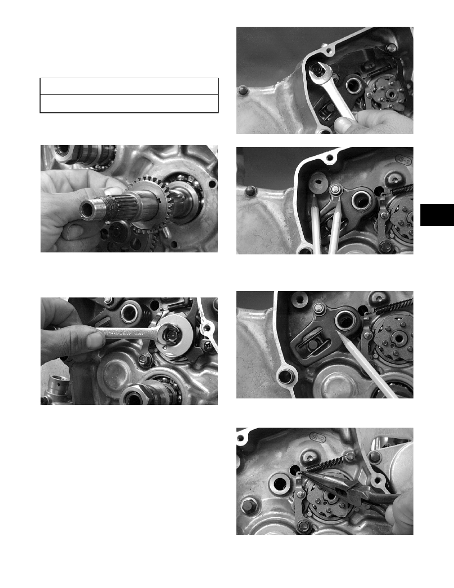
9. Remove the oil pump drive gear from the

crankshaft; then account for the pin.

4)

10. Remove the cap screw securing the gear shift

stopper plate pin retainer; then remove the

retainer.

4)

11. Remove the cap screw securing the gear shifting

arm assembly; remove the assembly and account

for a washer and a roller.

44)

45)

12. Remove the link arm and account for the spring

and the roller.

46)

13. Remove the spring from the cam stopper.

48)

 AT THIS POINT

 "    %" 1%

! $

RepairPro Service Manual

-------------------------------------------------------------------------------------------------------------------------------------------------------------

?

14. Remove the stopper plate and account for six pins.

Note the location of the alignment pin.

4?)

15. Remove the circlip securing the oil pump driven

gear; then remove the gear. Account for the pin.

49)

16. Remove the Phillips-head screws securing the oil

pump; then remove the pump.

447)

17. Remove the Phillips-head cap screws securing the

oil strainer cap. Note the arrow on the cap for

assembly purposes.

44)

18. Remove the Phillips-head screws securing the

strainer; then remove the strainer.

44)

Center Crankcase 

Components

„

 ! 

#$!

1"!!%(%

1%!!$

„

 /& !  "

 &!

 "&

!$

;$

 AT THIS POINT

 "   ! &

!%!."$

-------------------------------------------------------------------------------------------------------------------------------------------------------------

9

3

Separating Crankcase 

Halves

1. Remove the right-side cap screws securing the

crankcase halves. Note the location of the cap

screw with the copper washer.

4?)

2. Remove the left-side cap screws securing the

crankcase halves. Note the location of the

different-lengthed cap screws. 

3. Using a crankcase separator and tapping lightly

with a rubber mallet, separate the crankcase

halves. Account for two alignment pins and an

O-ring and remove a washer from the reverse

shifting cam.

„

 !# 

!

!

"$

4?4)

4?6)

Disassembling 

Crankcase Half

1. On the 300, remove the oil breather screen from

the crankcase. Note the direction of the tabs for

assembling purposes.

4?8)

RepairPro Service Manual

-------------------------------------------------------------------------------------------------------------------------------------------------------------

7

„

  / ! 8   

?6$

?6

„


 !,

1)1$

2. Remove the rear final driven gear w/shaft (A).

3. Remove the sub-transmission shaft assembly (B).

„

 4A4 

!&!

<=$

497)

4. On the 4x4, remove the secondary output shaft

(C); then account for the C-ring.

49)

5. Remove the cam stopper detent and gasket from

the crankcase.

-------------------------------------------------------------------------------------------------------------------------------------------------------------

3

49)

6. Remove the long shift shaft (D).

7. Remove the outer fork and center fork noting the

difference in the forks for assembling purposes.

8. Remove the reverse shifting cam (E).

9. Remove the inner fork (from the same shaft as in

step 7).

10. Remove the short shift shaft (F).

11. Remove the fork.

12. Remove the gear shifting cam (G).

13. Remove the spacer from the reverse idle shaft

assembly (H).

14. Remove the reverse idle shaft assembly (H).

Account for the gear, bushing, and washer.

15. Simultaneously, remove the driveshaft assembly

(I) and countershaft assembly (J) from the

crankcase.

575)

16. Using a crankshaft remover, push the crankshaft

assembly (L) out of the crankcase.

578)

17. Remove the Phillips-head screws securing the oil

pipe (K) to the crankcase.

Assembling Crankcase 

Half

„

 / &!

$

„

  ,  !   " 

!!$

 1. Place the oil pipe in position and secure to the

crankcase with the Phillips-head screws coated

with red Loctite #271.

 2. Using a crankshaft installer, install the crankshaft

assembly.

578)


3. Simultaneously, install the driveshaft and

countershaft assemblies into the crankcase.

 AT THIS POINT

 "   &  %"

! $

RepairPro Service Manual

-------------------------------------------------------------------------------------------------------------------------------------------------------------

575)

 4. Install the reverse idle shaft; then install a washer,

bushing, reverse idle gear, and a spacer.

574)

5. Install the gear shifting cam.

57)

6. Install the front gear shifting fork.

577)

7. Install the short gear shifting fork shaft.

499)

8. Install the inner shifting fork.

49?)

9. Install the reverse shifting cam and washer.

498)

4?6)

-------------------------------------------------------------------------------------------------------------------------------------------------------------

3

10. Install the center and outer shifting forks.

496)

495)

11. Install the long gear shifting fork shaft.

494)

12. Install the cam stopper detent with gasket onto the

crankcase.

49)

13. On the 4x4, place the C-ring into position; then

install the secondary output shaft noting the

location of the bearing alignment pin from

disassembly.

49)

497)

14. Install the sub-transmission shaft assembly.

4?9)

15. Install the final driven shaft and gear.

! CAUTION

-   ! "   !

" $

RepairPro Service Manual

-------------------------------------------------------------------------------------------------------------------------------------------------------------

4

4??)

16. On the 300, install the oil breather screen noting

the direction of the tabs from disassembly.

4?8)

Joining Crankcase 

Halves

 1. Verify that the alignment pins are in place and that

both case halves are clean and grease free. Apply

Three Bond Sealant (p/n 0636-070) to the mating

surfaces. Place the right-side half onto the left-side

half.

4?5)

 2. Using a plastic mallet, lightly tap the case halves

together until cap screws can be installed.

 3. From the left side, install the shift cable bracket

and the crankcase cap screws noting the location

of the different-lengthed cap screws; then tighten

only until snug.

„

  1       


!$

4?)

4?)

 4. From the right side, install the cap screws noting

the location of the cap screw with the copper

washer; then tighten only until snug.

„

  1       


!$

4?)

-------------------------------------------------------------------------------------------------------------------------------------------------------------

5

3

4?7)

 5. In a crisscross/case-to-case pattern, tighten the 8

mm cap screws until the halves are correctly

joined; then tighten to 2-2.4 kg-m (14.5-17 ft-lb).

„

  1       

 $

 6. In a crisscross/case-to-case pattern, tighten the 6

mm cap screws to 0.9-1.3 kg-m (6.5-9.5 ft-lb).

„

  1       

 $

Installing Right-Side 

Components

A. Oil Strainer/Oil Pump
B. Gear Shifting Arm

1. Place the oil strainer into position beneath the

crankcase and tighten with the Phillips-head cap

screws (coated with red Loctite #271) securely.

44)

2. Noting the arrow from disassembly, place the

strainer cap into position on the crankcase making

sure the O-ring is properly installed and secure

with the cap screws; then tighten the oil drain plug

to 2.2 kg-m (16 ft-lb).

44)

3. Place the oil pump into position on the crankcase

and secure with the Phillips-head screws coated

with blue Loctite #243. Tighten to 1 kg-m (7 ft-lb).

447)

4. Place the pin into position on the oil pump shaft,

install the oil pump driven gear making sure the

recessed side of the gear is directed inward, and

secure with the circlip.

 AT THIS POINT

!!

!,1%!

, (% !  

,!%!$

! CAUTION

 $

RepairPro Service Manual

-------------------------------------------------------------------------------------------------------------------------------------------------------------

6

49)

5. Place the stopper plate pins and the pin retainer

into position noting the alignment pin. Secure

assembly with the cap screw coated with red

Loctite #271. Tighten securely.

4?)

„

      !    

!$

6. Install the spring onto the cam stopper.

48)

7. Install the link arm making sure the spring and

roller are in position.

46)

8. Install the gear shifting arm assembly making sure

the washer and roller are properly positioned.

Secure with the cap screw coated with red Loctite

#271.

„

 B &

!!

 !!!!$

$

45)

449)

-------------------------------------------------------------------------------------------------------------------------------------------------------------

8

3

45)

C. Primary Gear Assembly
D. Primary Driven Clutch
E. Starter Clutch Shoe

„

  %! ?   !  

!!$

 9. Install the oil pump drive gear onto the crankshaft

making sure the pin is properly positioned.

„


$

4)

10. Install the primary driven washer and sleeve onto

the countershaft.

4)

7885

30

$ 2&)"*

$ ,1

$ B&

4$ &

5$ 

6$ (B

8$ (B

?$ 2&*&

9$ %!

7$ B

$ . 

$ B

4$ )"2

5$ )"2

6$ 2)

8$ %!

?$ !%

9$ 12

7$ 22

$ >

$ *>

$ *>,

4$ 1>

5$ ;%

6$ ;

8$ 1

?$ !%

9$ !%

7$ 

$ !%%

RepairPro Service Manual

-------------------------------------------------------------------------------------------------------------------------------------------------------------

?

11. Install the primary gear assembly housing onto the

countershaft; then install the washer.

45)

45)

12. Place the clutch hub on a work bench; then

alternately install the 6 drive clutch fiber plates

and the 5 driven clutch steel plates onto the hub

making sure the marks made during servicing on

the hub and plates align.

8)

13. Install the pressure disc onto the plates making

sure the marks scribed during removing are

aligned.

448)

„

 , 

"& &!

 !

!&

 $

„


 &!!&$

44?)

14. Place the primary driven clutch assembly onto the

countershaft.

„


!&" &"$

! CAUTION

 A "    !   "

"   !    &

"

 !$

! CAUTION

       ! 

 !!!$,&

  !      

" &

!!!&$

-------------------------------------------------------------------------------------------------------------------------------------------------------------

9

3

47)

15. Using a clutch sleeve hub holder, install the nut

and washer. Tighten to 8 kg-m (58 ft-lb).

4?)

16. Place the primary drive one-way clutch housing

onto the crankshaft.

17. Install the clutch shoe and washer; then secure

with the starter clutch-shoe nut (left-hand threads).

Tighten to 11 kg-m (79.5 ft-lb).

46)

18. Install the release roller assembly making sure the

four springs are in position; then using a crisscross

pattern, tighten the four cap screws securely.

„

       & !

!

 !

$

45)

19. Slide the clutch release arm and gear shift shaft

into the crankcase.

44)

F. Release Roller Guide
G. Cover

„

 %!9! 

!!$

„


!

!$

4)

20. Install the right-side cover onto the right side

crankcase half making sure the release roller guide

remains correctly positioned; then install the cap

screws. Note the proper locations of the long cap

screw with rubber washer and the two wire forms.

RepairPro Service Manual

-------------------------------------------------------------------------------------------------------------------------------------------------------------

7

4)

4)

 21. Tighten the cap screws in a crisscross pattern to

0.9-1.3 kg-m (6.5-9.5 ft-lb).

Installing Left-Side 

Components

A. Idle Gear Assembly
B. Magneto Rotor

1. Place the shift-indicator sending unit into position

making sure the neutral contact and spring are

inside the case and a well-oiled O-ring is properly

positioned. Secure with Phillips-head screws.

489)

48?)

2. Place the spacer and bushing (noting the location

of the oil hole) onto the driveshaft and place the

gear and washer onto the driveshaft; then secure

with the circlip.

486)

485)

484)

-------------------------------------------------------------------------------------------------------------------------------------------------------------

3

48)

3. Place a round washer onto the sub-transmission

shaft; then install the driven gear and notched

washer. Secure with a circlip.

„


"$

48)

487)

4. Install the sub-transmission gear cam.

469)

5. Install the idler gear and washers noting the thick

washer on the inside from disassembly.

488)

46?)

6. Install the drive gear dog onto the driveshaft.

468)

RepairPro Service Manual

-------------------------------------------------------------------------------------------------------------------------------------------------------------

7. Place the driven gear dog onto the

sub-transmission shaft.

466)

8. Install the long shift fork.

465)

9. Install the long shift fork shaft.

464)

10. Install the short shift fork.

46)

11. Install the short shift fork shaft.

46)

12. Place the drive gear and washer on the driveshaft.

13. Install the driven gear and washer.

467)

14. Install the cam chain; then install the starter clutch

gear assembly.

-------------------------------------------------------------------------------------------------------------------------------------------------------------


Content      ..     3      4      5      6     ..