Suzuki GSX-R1000. Service Manual - part 6
 

  Index      Manuals     Suzuki GSX-R1000. Service Manual


Search            copyright infringement  


Content      ..     4      5      6      7     ..


Suzuki GSX-R1000. Service Manual - part 6


1A-18 Engine General Information and Diagnosis: 

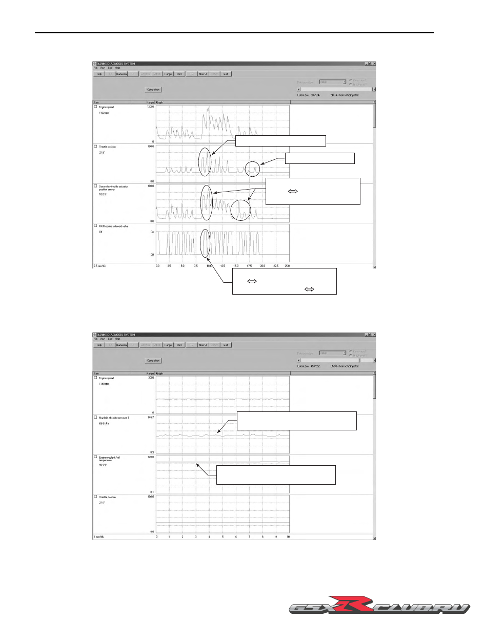
Data at the time of racing

Data of intake negative pressure during idling (100 

°

C)

Throttle: Slowly open

PAIR control solenoid valve 
ON       OFF in according with 
the throttle valve opens       closes

Throttle: Quick wide open

Secondary throttle valve 
opens       closes in according 
with the throttle valve opening

I947H1110148-01

Check the manifold absolute pressure.

XXX kPa

Check the engine coolant temperature.

XX ˚C

I947H1110149-01

-------------------------------------------------------------------------------------------------------------------------------------------------------------

Engine General Information and Diagnosis:  1A-19

Data of manifold absolute pressure operation at the time of starting

Check the manifold absolute pressure.

XXX kPa

I947H1110150-01

-------------------------------------------------------------------------------------------------------------------------------------------------------------

1A-20 Engine General Information and Diagnosis: 

Example of Trouble

Three data; value 3 (current data 3), value 1 (past data 1) and value 2 (past data 2); can be made in comparison by 
showing them in the graph. Read the change of value by comparing the current data to the past data that have been 
saved under the same condition, then you may determine how changes have occurred with the passing of time and 
identify what problem is currently occurring.

NOTE

With DTC not output, if the engine idling speed and ISC valve stepping position are found to be 
abnormal than the data saved previously, the possible cause may probably lie in the hardware side 
such as ISC valve air inlet hose crumple, bend, etc.


DTC Table

B947H11104006

Unstable idling speed

No DTC output

Abnormal value of ISC valve position

I947H1110151-02

Code

Malfunction Part

Remarks

C00

None

No defective part

C11 (P0340)

)

(Page 1A-29)

Camshaft position sensor (CMPS)

C12 (P0335)

)

(Page 1A-32)

Crankshaft position sensor (CKPS)

Pick-up coil signal, signal generator

C13 (P0105-H/L)

)

(Page 1A-35)

Intake air pressure sensor (IAPS)

C14 (P0120-H/L)

)

(Page 1A-43)

Throttle position sensor (TPS)

*1

C15 (P0115-H/L) 

)

(Page 1A-50)

Engine coolant temperature sensor (ECTS)

C21 (P0110-H/L)

)

(Page 1A-55)

Intake air temperature sensor (IATS)

C22 (P1450-H/L)

)

(Page 1A-60)

Atmospheric pressure sensor (APS)

C23 (P1651-H/L)

)

(Page 1A-68)

Tip-over sensor (TOS)

C24 (P0351)

)

(Page 1A-75)

Ignition signal #1 (IG coil #1)

For #1 cylinder

-------------------------------------------------------------------------------------------------------------------------------------------------------------

Engine General Information and Diagnosis:  1A-21

In the LCD (DISPLAY) panel, the malfunction code is indicated from small code to large code.
*1 To get the proper signal from the throttle position sensor, the sensor basic position is indicated in the LCD 
(DISPLAY) panel. The malfunction code is indicated in three digits. In front of the three digits, a line appears in any of 
the three positions, upper, middle or lower line. If the indication is upper or lower line when engine rpm is 1 200 r/min, 
slightly turn the throttle position sensor and bring the line to the middle.

C25 (P0352)

)

(Page 1A-75)

Ignition signal #2 (IG coil #2)

For #2 cylinder

C26 (P0353) 

)

(Page 1A-75)

Ignition signal #3 (IG coil #3)

For #3 cylinder

C27 (P0354)

)

(Page 1A-75)

Ignition signal #4 (IG coil #4)

For #4 cylinder

C28 (P1655)

)

(Page 1A-75)

Secondary throttle valve actuator (STVA)

C29 (P1654-H/L)

)

(Page 1A-79)

Secondary throttle position sensor (STPS)

C31 (P0705)

)

(Page 1A-86)

Gear position signal (GP switch)

C32 (P0201)

)

(Page 1A-88)

Primary Injector signal #1

For #1 cylinder

C33 (P0202)

)

(Page 1A-88)

Primary Injector signal #2

For #2 cylinder

C34 (P0203)

)

(Page 1A-88)

Primary Injector signal #3

For #3 cylinder

C35 (P0204)

)

(Page 1A-88)

Primary Injector signal #4

For #4 cylinder

C36 (P1764)

)

(Page 1A-91)

Secondary Injector signal #1

For #1 cylinder

C37 (P1765)

)

(Page 1A-91)

Secondary Injector signal #2

For #2 cylinder

C38 (P1766)

)

(Page 1A-91)

Secondary Injector signal #3

For #3 cylinder

C39 (P1767)

)

(Page 1A-91)

Secondary Injector signal #4

For #4 cylinder

C40 (P0505/P0506/

P0507)

)

(Page 1A-94)

Idle speed control valve (ISC valve)

C41 (P0230-H/L, 

P2505)

)

(Page 1A-98) / 

)

(Page 1A-101)

Fuel pump control system (FP control system), 
ECM/PCM power input signal

Fuel pump, fuel pump relay

C42 (P1650) 

)

(Page 1A-103)

Ignition switch signal (Anti-theft)

Ignition switch for E-03, 14, 28, 33/immobilizer 
for E-02, 19, 24, 51

C44 (P0130, 

P0135) 

)

(Page 1A-103)

Heated oxygen sensor (HO2S)

C46 (P1657-H/L, 

P1658)

)

(Page 1A-109)

Exhaust control valve actuator (EXCVA)

C49 (P1656)

)

(Page 1A-121)

PAIR control solenoid valve

C60 (P0480) 

)

(Page 1A-124)

Cooling fan control system

Cooling fan relay

C62 (P0443)

)

(Page 1A-127)

EVAP system purge control solenoid valve 

E-33 only

C91 (P0500)

)

(Page 1A-131)

Vehicle speed sensor

C93 (P1769)

)

(Page 1A-134)

Steering damper solenoid valve

Code

Malfunction Part

Remarks

-------------------------------------------------------------------------------------------------------------------------------------------------------------

1A-22 Engine General Information and Diagnosis: 

Fail-Safe Function Table

B947H11104007

FI system is provided with fail-safe function to allow the engine to start and the motorcycle to run in a minimum 
performance necessary even under malfunction condition.

Item

Fail-Safe Mode

Starting Ability

Running Ability

CMP sensor

When camshaft position signal has failed 
during running, the ECM determines the 
cylinder positions as # to be the same as 
before occurrence of such a failure.

“NO”

“YES”

Motorcycle can run, but once engine 
stops, engine can not start.

IAP sensor

Intake air pressure value is fixed to 101 KPa 
(760 mmHg).

“YES”

“YES”

TP sensor

The throttle opening is fixed to full open 
position.
Ignition timing is also fixed.

“YES”

“YES”

ECT sensor

Engine coolant temperature value is fixed to 
80 

°

C (176 

°

F).

Cooling fan is fixed on position.

“YES”

“YES”

IAT sensor

Intake air temperature value is fixed to 40 

°

(104 

°

F).

“YES”

“YES”

AP sensor

Atmospheric pressure is fixed to 101 kPa 
(760 mmHg).

“YES”

“YES”

Ignition signal

#1 fuel-cut
(primary side and secondary side)

“YES”

“YES”

#2, #3 & #4 cylinders can run.

#2 fuel-cut
(primary side and secondary side)

“YES”

“YES”

#1, #3 & #4 cylinders can run.

#3 fuel-cut
(primary side and secondary side)

“YES”

“YES”

#1, #2 & #4 cylinders can run.

#4 fuel-cut
(primary side and secondary side)

“YES”

“YES”

#1, #2 & #3 cylinders can run.

Primary injection signal

“YES”

“YES”

#2, #3 & #4 cylinders can run.

“YES”

“YES”

#1, #3 & #4 cylinders can run.

“YES”

“YES”

#1, #2 & #4 cylinders can run.

“YES”

“YES”

#1, #2 & #3 cylinders can run.

Secondary injection signal

“YES”

#2, #3 & #4 cylinders can run.

“YES”

#1, #3 & #4 cylinders can run.

“YES”

#1, #2 & #4 cylinders can run.

“YES”

#1, #2 & #3 cylinders can run.

STV actuator

Secondary throttle valve is fixed to full close 
position. When motor disconnection or lock 
occurs, power from ECM is shut off.

“YES”

“YES”

STP sensor

Secondary throttle valve is fixed to full open 
position.

“YES”

“YES”

Gear position signal

Gear position signal is fixed to 6th gear.

“YES”

“YES”

HO2 sensor

Feedback compensation is inhibited. (Air/
fuel ratio is fixed to normal.)

“YES”

“YES”

PAIR control solenoid valve

ECM stops controlling PAIR control solenoid 
valve.

“YES”

“YES”

EXCV actuator

EXCV actuator is fixed to full open position. 
When motor disconnection or lock occurs, 
power from ECM is shut off.

“YES”

“YES”

ISC valve

When motor disconnection or lock occurs, 
power from ECM is shut off.

“YES”

“YES”

-------------------------------------------------------------------------------------------------------------------------------------------------------------

Engine General Information and Diagnosis:  1A-23

The engine can start and can run even if the signal in the table is not received from each sensor. But, the engine 
running condition is not complete, providing only emergency help (by fail-safe circuit). In this case, it is necessary to 
bring the motorcycle to the workshop for complete repair.
When two ignition signals or two injector signals are not received by ECM, the fail-safe circuit can not work and ignition 
or injection is stopped.

FI System Troubleshooting

B947H11104008

Customer Complaint Analysis

Record details of the problem (failure, complaint) and how it occurred as described by the customer. For this purpose, 
use of such an inspection form such as following will facilitate collecting information to the point required for proper 
analysis and diagnosis.

NOTE

This form is a standard sample. The form should be modified according to conditions and 
characteristic of each market.


EXAMPLE: CUSTOMER PROBLEM INSPECTION FORM

EVAP system purge control 
solenoid valve (E-33 only)

ECM stops controlling EVAP system purge 
control solenoid valve.

“YES”

“YES”

Vehicle speed sensor

ECM stops controlling steering damper 
solenoid valve.

“YES”

“YES”

Steering damper solenoid 
valve

ECM stops controlling steering damper 
solenoid valve.

“YES”

“YES”

User name:

Model:

VIN:

Date of issue:

Date Reg.:

Date of problem:

Mileage:

Malfunction indicator 
light condition (LED)


†

 Always ON / 

†

 Sometimes ON / 

†

 Always OFF / 

†

 Good condition

Malfunction display/code 
(LCD)

User mode: 

†

 No display / 

†

 Malfunction display (              )

Dealer mode: 

†

 No code / 

†

 Malfunction code (              )

PROBLEM SYMPTOMS

†

 Difficult Starting

†

 Poor Driveability

†

 No cranking

†

 Hesitation on acceleration

†

 No initial combustion

†

 Back fire / 

†

 After fire

†

 No combustion

†

 Lack of power

†

 Poor starting at

†

 Surging

      (

†

 cold / 

†

 warm / 

†

 always)

†

 Abnormal knocking

†

 Other

†

 Engine rpm jumps briefly

†

 Other 

†

 Poor Idling

†

 Engine Stall when

†

 Poor fast Idle

†

 Immediately after start

†

 Abnormal idling speed

†

 Throttle valve is opened

     (

†

 High / 

†

 Low) (         r/min)

†

 Throttle valve is closed

†

 Unstable

†

 Load is applied

†

 Hunting (         r/min to         r/min)

†

 Other                     

†

 Other

†

 OTHERS:

Item

Fail-Safe Mode

Starting Ability

Running Ability

-------------------------------------------------------------------------------------------------------------------------------------------------------------

1A-24 Engine General Information and Diagnosis: 

Visual Inspection

Prior to diagnosis using the mode select switch or SDS, perform the following visual inspections. The reason for visual 
inspection is that mechanical failures (such as oil leakage) cannot be displayed on the screen with the use of mode 
select switch or SDS.

• Engine oil level and leakage. Refer to “Engine Oil and Filter Replacement” in Section 0B (Page 0B-10).

• Engine coolant level and leakage. Refer to “Cooling Circuit Inspection” in Section 1F (Page 1F-4).

• Fuel level and leakage. Refer to “Fuel Line Inspection” in Section 0B (Page 0B-10).

• Clogged air cleaner element. Refer to “Air Cleaner Element Inspection” in Section 0B (Page 0B-3).

• Battery condition.

• Throttle cable play. Refer to “Throttle Cable Play Inspection and Adjustment” in Section 0B (Page 0B-12).

• Vacuum hose looseness, bend and disconnection.

• Broken fuse.

• FI indicator light operation. Refer to “Combination Meter Inspection” in Section 9C (Page 9C-3).

• Each warning indicator light operation. Refer to “Combination Meter Inspection” in Section 9C (Page 9C-3).

• Speedometer operation. Refer to “Speedometer Inspection” in Section 9C (Page 9C-5).

• Exhaust gas leakage and noise. Refer to “Exhaust System Inspection” in Section 1K (Page 1K-13).

• Each coupler disconnection.

• Clogged radiator fins. Refer to “Radiator Inspection and Cleaning” in Section 1F (Page 1F-5).

MOTORCYCLE/ENVIRONMENTAL CONDITION WHEN PROBLEM OCCURS

Environmental condition

Weather

†

 Fair / 

†

 Cloudy / 

†

 Rain / 

†

 Snow / 

†

 Always / 

†

 Other

Temperature

†

 Hot / 

†

 Warm / 

†

 Cool / 

†

 Cold ( 

°

C / 

°

F) / 

†

 Always

Frequency

†

 Always / 

†

 Sometimes ( times / day, month) / 

†

 Only once

†

 Under certain condition

Road

†

 Urban / 

†

 Suburb / 

†

 Highway / 

†

 Mountainous (

†

 Uphill / 

†

 Downhill)

†

 Tarmacadam / 

†

 Gravel / 

†

 Other

Motorcycle condition

Engine condition

†

 Cold / 

†

 Warming up phase / 

†

 Warmed up / 

†

 Always / 

†

 Other at starting

†

 Immediately after start / 

†

 Racing without load / 

†

 Engine speed (     r/min)

Motorcycle condition During driving: 

†

 Constant speed / 

†

 Accelerating / 

†

 Decelerating

†

 Right hand corner / 

†

 Left hand corner

†

 At stop / 

†

 Motorcycle speed when problem occurs (        km/h,         mile/h)

†

 Other:

-------------------------------------------------------------------------------------------------------------------------------------------------------------

Engine General Information and Diagnosis:  1A-25

Malfunction Code and Defective Condition Table

B947H11104009

Malfunction 

Code

Detected Item

Detected Failure Condition

Check For

C00

NO FAULT

C11

CMP sensor

The signal does not reach ECM for 3 sec. or 
more, after receiving the starter signal.

CMP sensor wiring and 
mechanical parts
CMP sensor, intake cam pin, 
wiring/coupler connection

P0340

C12

CKP sensor

The signal does not reach ECM for 3 sec. or 
more, after receiving the starter signal.

CKP sensor wiring and 
mechanical parts
CKP sensor, lead wire/coupler 
connection

P0335

C13

IAP sensor

The sensor should produce following voltage.
0.5 V 

 Sensor voltage < 4.85 V

In other than the above range, C13 (P0105) is 
indicated.

IAP sensor, lead wire/coupler 
connection

P0105

H

Sensor voltage is higher than specified value.

IAP sensor circuit shorted to 
VCC or ground circuit open

L

Sensor voltage is lower than specified value.

IAP sensor circuit open or 
shorted to ground or VCC 
circuit open

C14

TP sensor

The sensor should produce following voltage.
0.2 V 

 Sensor voltage < 4.8 V

In other than the above range, C14 (P0120) is 
indicated.

TP sensor, lead wire/coupler 
connection

P0120

H

Sensor voltage is higher than specified value.

TP sensor circuit shorted to 
VCC or ground circuit open

L

Sensor voltage is lower than specified value.

TP sensor circuit open or 
shorted to ground or VCC 
circuit open

C15

ECT sensor

The sensor voltage should be the following.
0.15 V 

 Sensor voltage < 4.85 V

In other than the above range, C15 (P0115) is 
indicated.

ECT sensor, lead wire/coupler 
connection

P0115

H

Sensor voltage is higher than specified value.

ECT sensor circuit open or 
ground circuit open

L

Sensor voltage is lower than specified value.

ECT sensor circuit shorted to 
ground

C21

IAT sensor

The sensor voltage should be the following.
0.15 V 

 Sensor voltage < 4.85 V

In other than the above range, C21 (P0110) is 
indicated.

IAT sensor, lead wire/coupler 
connection

P0110

H

Sensor voltage is higher than specified value.

IAT sensor circuit open or 
ground circuit open

L

Sensor voltage is lower than specified value.

IAT sensor circuit shorted to 
ground

C22

AP sensor

The sensor voltage should be the following.
0.5 V 

 Sensor voltage < 4.85 V

In other than the above range, C22 (P1450) is 
indicated.

AP sensor, lead wire/coupler 
connection

P1450

H

Sensor voltage is higher than specified value.

AP sensor circuit shorted to 
VCC or ground circuit open

L

Sensor voltage is lower than specified value.

AP sensor circuit open or 
shorted to ground or VCC 
circuit open

-------------------------------------------------------------------------------------------------------------------------------------------------------------

1A-26 Engine General Information and Diagnosis: 

C23

TO sensor

The sensor voltage should be the following for 
2 sec. and more, after ignition switch is turned 
ON.
0.2 V 

 Sensor voltage < 4.8 V

In other than the above value, C23 (P1651) is 
indicated.

TO sensor, lead wire/coupler 
connection

P1651

H

Sensor voltage is higher than specified value.

TO sensor circuit shorted to 
VCC or ground circuit open

L

Sensor voltage is lower than specified value.

TO sensor circuit open or 
shorted to ground or VCC 
circuit open

C24/C25
C26/C27

Ignition signal

CKP sensor (pick-up coil) signal is produced, 
but signal from ignition coil is interrupted 8 
times or more continuously. In this case, the 
code C24 (P0351), C25 (P0352), C26 (P0353) 
or C27 (P0354) is indicated.

Ignition coil, wiring/coupler 
connection, power supply from 
the battery

P0351/P0352
P0353/P0354

C28

STV actuator

When no actuator control signal is supplied 
from the ECM, communication signal does not 
reach ECM or operation voltage does not 
reach STVA motor, C28 (P1655) is indicated. 
STVA can not operate properly or its motor 
locked.

STVA motor, STVA lead wire/
coupler connection

P1655

C29

STP sensor

The sensor should produce following voltage.
0.15 V 

 Sensor voltage < 4.85 V

In other than the above range, C29 (P1654) is 
indicated.

STP sensor, lead wire/coupler 
connection

P1654

H

Sensor voltage is higher than specified value.

STP sensor circuit shorted to 
VCC or ground circuit open

L

Sensor voltage is lower than specified value.

STP sensor circuit open or 
shorted to ground or VCC 
circuit open

C31

Gear position signal

Gear position signal voltage should be higher 
than the following for 3 seconds and more.
Gear position sensor voltage 

 0.6 V

If lower than the above value, C31 (P0705) is 
indicated.

GP switch, wiring/coupler 
connection, gearshift cam, etc.

P0705

C32/C33
C34/C35

Primary fuel injector

CKP sensor (pickup coil) signal is produced, 
but fuel injector signal is interrupted 4 times or 
more continuously. In this case, the code C32 
(P0201), C33 (P0202), C34 (P0203) or C35 
(P0204) is indicated.

Primary fuel injector, wiring/
coupler connection, power 
supply to the injector

P0201/P0202
P0203/P0204

C36/C37
C38/C39

Secondary fuel injector

Some failure exists in the fuel injector signal in 
a high load, high revolution condition. In this 
case, the code C36 (P1764), C37 (P1765), 
C38 (P1766) or C39 (P1767) is indicated.

Secondary fuel injector, wiring/
coupler connection, power 
supply to the injector

P1764/P1765
P1766/P1767

C40/P0505

ISC valve

The circuit voltage of motor drive is unusual.

ISC valve circuit open or 
shorted to ground
Power source circuit open

C40/P0506

Idle speed is lower than the desired idle 
speed.

Air passage clogged
ISC valve is fixed
ISC valve preset position is 
incorrect

C40/P0507

Idle speed is higher than the desired idle 
speed.

ISC valve hose connection
ISC valve is fixed
ISC valve preset position is 
incorrect

Malfunction 

Code

Detected Item

Detected Failure Condition

Check For

-------------------------------------------------------------------------------------------------------------------------------------------------------------

Engine General Information and Diagnosis:  1A-27

C41

FP relay

No voltage is applied to the fuel pump, 
although fuel pump relay is turned ON, or 
voltage is applied to fuel pump although fuel 
pump relay is turned OFF.

Fuel pump relay, lead wire/
coupler connection, power 
source to fuel pump relay and 
fuel injectors

P0230

H

Voltage is applied to fuel pump although fuel 
pump relay is turned OFF.

Fuel pump relay switch circuit 
shorted to power source
Fuel pump relay (switch side)

L

No voltage is applied to the fuel pump, 
although fuel pump relay is turned ON.

Fuel pump relay circuit open or 
short
Fuel pump relay (coil side)

C41/P2505

ECM/PCM power input 
signal

No voltage is applied to the ECM.

Lead wire/coupler connection 
of ECM terminal to fuel fuse

C42

Ignition switch

Ignition switch signal is not input to the ECM.
* When the I.D. agreement is not verified.
* ECM does not receive communication signal 
from the immobilizer antenna.

Ignition switch, lead wire/
coupler, etc.
* Immobilizer/anti-theft system

P1650

C44/P0130

HO2 sensor

HO2 sensor output voltage is not input to ECM 
during engine operation and running 
condition.
(Sensor voltage > 1.0 V)
C44 (P0130) is indicated.

HO2 sensor is circuit open or 
shorted to the power source

C44/P0135

The Heater can not operate so that heater 
operation voltage is not supply to the oxygen 
heater circuit, C44 (P0135) is indicated.

Heated circuit open or shorted 
to ground
Battery voltage supply to the 
HO2 sensor

C46

EXCV actuator

EXCVA position sensor produces following 
voltage.
0.14 V 

 sensor voltage < 4.9 V

In other than the above range, C46 (P1675) is 
indicated.
When no actuator control signal is supplied 
from the ECM, communication signal does not 
reach ECM or operation voltage does not 
reach EXCVA motor, C46 (P1658) is 
indicated. EXCVA can not operate.

EXCVA, EXCVA lead wire/
coupler

P1657

H

EXCVA position sensor voltage is higher than 
specified value.

EXCVA position sensor circuit 
shorted to VCC or ground 
circuit open

L

EXCVA position sensor voltage is lower than 
specified value.

EXCVA position sensor circuit 
open or shorted to ground or 
VCC circuit open

P1658

When no operation voltage reaches EXCVA 
motor, C46 (P1658) is indicated. EXCVA 
motor can not be operated.

EXCVA, EXCVA motor lead 
wire/coupler

C49

PAIR control solenoid 
valve

PAIR control solenoid valve voltage is not 
input to ECM.

PAIR control solenoid valve, 
lead wire/coupler connection

P1656

C60

Cooling fan relay 

Cooling fan relay signal is not input to ECM.

Cooling fan relay, lead wire/
coupler connection

P0480

C62

EVAP system purge 
control solenoid valve 
(E-33 only)

EVAP system purge control solenoid valve 
voltage is not input to ECM.

EVAP system purge control 
solenoid valve, lead wire/
coupler connection

P0443

Malfunction 

Code

Detected Item

Detected Failure Condition

Check For

-------------------------------------------------------------------------------------------------------------------------------------------------------------

1A-28 Engine General Information and Diagnosis: 

* : Immobilizer system equipped model only. (E-02, 19, 24, 51)

C91

Vehicle speed sensor

Speedometer does not receive signal from the 
vehicle speed sensor for more than 6 sec. 
when the motorcycle is running.
ECM does not receive signal from the vehicle 
speed sensor for more than 6 sec. when the 
motorcycle is running.
Failure in communication between ECM and 
speedometer with reference to vehicle speed.

Speed sensor and 
speedometer wiring/coupler 
connection between ECM and 
speedometer

P0500

C93

Steering damper 
solenoid valve

Steering damper control current does not flow 
to the solenoid valve.
With IG turned ON, ECM detects a failure of 
internal circuit element. Solenoid current does 
not converge to the target value. Battery 
voltage is 10 V or below with the engine 
running.

Steering damper solenoid valve 
circuit interrupter element 
shorted, feedback current 
convergence failure, low 
battery voltage

P1769

H

Steering damper control current is higher than 
specified value.
An abnormal current is detected during the 
vehicle standstill. Solenoid current is 0.7 A or 
above.

Steering damper solenoid valve 
circuit shorted to VCC

L

Steering damper control current is lower than 
specified value.
With IG turned ON, ECM detects a 
discontinuity. An abnormal current is detected 
during the vehicle standstill.

Steering damper solenoid valve 
circuit open or shorted

Malfunction 

Code

Detected Item

Detected Failure Condition

Check For

-------------------------------------------------------------------------------------------------------------------------------------------------------------

Engine General Information and Diagnosis:  1A-29

DTC “C11” (P0340): CMP Sensor Circuit Malfunction

B947H11104010

Detected Condition and Possible Cause

Wiring Diagram

ECM coupler (Harness side)

Troubleshooting

CAUTION

!


When using the multi-circuit tester, do not strongly touch the terminal of the ECM coupler with a
 needle pointed tester probe to prevent terminal damage.


NOTE

After repairing the trouble, clear the DTC using SDS tool. Refer to “Use of SDS Diagnosis Reset 
Procedures” (Page 1A-14).


Detected Condition

Possible Cause

The signal does not reach ECM for 3 sec. or more, after 
receiving the starter signal.

• CMP sensor circuit open or short.

• CMP sensor malfunction.

• ECM malfunction.

ECM

VCC

E2

CMP sensor

CMPS

7

8

35

B/Bl

W

B/Br

R

B/Y

Bl/Y

I837H1110006-01

1

2

3

4

5

6

7

8

9 10 11 12

13 14 15 16 17 18 19 20 21 22 23 24

25 26 27 28 29 30 31 32 33 34 35 36

37 38 39 40 41 42 43 44 45 46 47 48

49 50 51 52 53 54 55 56 57 58 59 60

61 62 63 64 65 66 67 68 69 70 71 72

I837H1110007-02

-------------------------------------------------------------------------------------------------------------------------------------------------------------

1A-30 Engine General Information and Diagnosis: 

Step

Action

Yes

No

1

1) Turn the ignition switch OFF.

2) Lift and support the fuel tank. Refer to “Fuel Tank 

Removal and Installation” in Section 1G (Page 1G-9).

3) Remove the air cleaner box. Refer to “Air Cleaner Box 

Removal and Installation” in Section 1D (Page 1D-7).

4) Check the CMP sensor coupler (1) for loose or poor 

contacts.
If OK, remove the CMP sensor. Refer to “CMP Sensor 
Removal and Installation” in Section 1C (Page 1C-2)
.

5) Connect 3 new 1.5 V batteries in series, 1 k

 resistor 

and the multi-circuit tester as shown in the figure.

Special tool

:  09900–25008 (Multi circuit tester set)

Tester knob indication
Voltage (

)

• B/Y, R or B/Br wire 

open or shorted to 
ground.

• Loose or poor 

contacts on the CMP 
sensor coupler or 
ECM coupler 
(Terminal “7”, “8” or 
“35”).

• If wires and 

connection are OK, 
intermittent trouble or 
faulty ECM.

• Recheck each 

terminal and wire 
harness for open 
circuit and poor 
connection.

• Replace the ECM 

with a known good 
one, and inspect it 
again. 

• Inspect that metal 

particles or foreign 
material stuck on the 
CMP sensor and 
camshaft tip.

• If there are no metal 

particles and foreign 
material, then replace 
the CMP sensor with 
a new one. 

1

I947H1110010-01

1 k

W

Bl/Y

B/Bl

(+)

(–)

I823H1110005-04

-------------------------------------------------------------------------------------------------------------------------------------------------------------

Engine General Information and Diagnosis:  1A-31

Step

Action

Yes

No

1

6) Under this condition, if a suitable screwdriver touching 

the pick-up surface of the CMP sensor is moved, the 
tester reading voltage changes (0.8 V and less 

 4.3 V 

and more).

Is the voltage OK?

• B/Y, R or B/Br wire 

open or shorted to 
ground.

• Loose or poor 

contacts on the CMP 
sensor coupler or 
ECM coupler 
(Terminal “7”, “8” or 
“35”).

• If wires and 

connection are OK, 
intermittent trouble or 
faulty ECM.

• Recheck each 

terminal and wire 
harness for open 
circuit and poor 
connection.

• Replace the ECM 

with a known good 
one, and inspect it 
again. 

• Inspect that metal 

particles or foreign 
material stuck on the 
CMP sensor and 
camshaft tip.

• If there are no metal 

particles and foreign 
material, then replace 
the CMP sensor with 
a new one. 

I823H1110007-01

-------------------------------------------------------------------------------------------------------------------------------------------------------------

1A-32 Engine General Information and Diagnosis: 

DTC “C12” (P0335): CKP Sensor Circuit Malfunction

B947H11104011

Detected Condition and Possible Cause

Wiring Diagram

ECM coupler (Harness side)

Troubleshooting

CAUTION

!


When using the multi-circuit tester, do not strongly touch the terminal of the ECM coupler with a 
needle pointed tester probe to prevent terminal damage.


NOTE

After repairing the trouble, clear the DTC using SDS tool. Refer to “Use of SDS Diagnosis Reset 
Procedures” (Page 1A-14).


Detected Condition

Possible Cause

The signal does not reach ECM for 3 sec. or more, after 
receiving the starter signal.

• Metal particles or foreign material being stuck on the 

CKP sensor and rotor tip.

• CKP sensor circuit open or short.

• CKP sensor malfunction.

• ECM malfunction.

ECM

CKP sensor

CKP

CKP

G/W

Bl/Y

B

G/BI

9

21

I947H1110011-01

1

2

3

4

5

6

7

8

9 10 11 12

13 14 15 16 17 18 19 20 21 22 23 24

25 26 27 28 29 30 31 32 33 34 35 36

37 38 39 40 41 42 43 44 45 46 47 48

49 50 51 52 53 54 55 56 57 58 59 60

61 62 63 64 65 66 67 68 69 70 71 72

I837H1110007-02

-------------------------------------------------------------------------------------------------------------------------------------------------------------

Engine General Information and Diagnosis:  1A-33

Step

Action

Yes

No

1

1) Turn the ignition switch OFF.

2) Lift and support the fuel tank. Refer to “Fuel Tank 

Removal and Installation” in Section 1G (Page 1G-9).

3) Check the CKP sensor coupler (1) for loose or poor 

contacts.
If OK, then measure the CKP sensor resistance.

4) Disconnect the CKP sensor coupler and measure the 

CKP sensor resistance.

Special tool

(A):  09900–25008 (Multi circuit tester set)

Tester knob indication
Resistance (

)

CKP sensor resistance
142 – 194 

 (B – Bl/Y)

Go to Step 2.

Replace the CKP 
sensor with a new one.

1

I947H1110012-01

(A)

I947H1110013-01

-------------------------------------------------------------------------------------------------------------------------------------------------------------


Content      ..     4      5      6      7     ..