CFMoto motorcycle CF650NK. Service Manual - part 22
 

  Index      Manuals     CFMoto motorcycle CF650NK. Service Manual


Search            copyright infringement  


Content      ..     20      21      22      23     ..


CFMoto motorcycle CF650NK. Service Manual - part 22


CLUTCH 6-13

Clutch

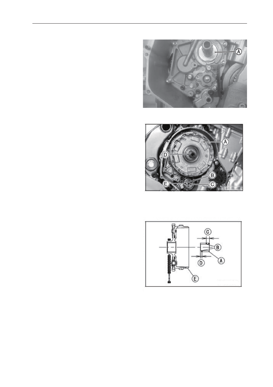
 Be sure that the spacer [A] is in position.


 Insert the following on the drive shaft.

   Clutch Housing [A] with Chain [B] and  Sprocket 
   [C]

 Align [E] the hole on the oil pump sprocket with 

   the oil pump shaft. 

 Apply engine oil on the sleeve [D] and insert to 

   Clutch Housing [A].  


 NOTE


Insert the sleeve into the clutch housing, noting 

   its direction as shown.

   Sleeve [A] 
   Oil Holes [B]  
    Long Distance [C] 
   Short Distance [D] 
   Clutch Housing [E]

-------------------------------------------------------------------------------------------------------------------------------------------------------------

6-14 CLUTCH

Clutch

 Install the following parts on the drive shaft.

   Spacer [A] 
   Clutch Hub [B]
   Washer [C] 
   Elastic  washer[D]
   Nut [E]

 Install the washer so that the OUTSIDE mark [A]  

   faces outward.

 Replace the clutch hub nut with a new one and 

   apply screw fastening grease.

 Holding the clutch hub, tighten the clutch hub 

    nut. 

Special Tool -  Clutch Holder
Torque - Clutch Hub Nut: 132 N·m 

-------------------------------------------------------------------------------------------------------------------------------------------------------------

CLUTCH 6-15

Clutch

 Install the friction plates and steel plates, starting 

   with a friction plate and alternating them. 

CAUTION

If new dry friction plates and steel plates are 
installed, apply engine oil to the surfaces of 
each plate to avoid clutch plate seizure.

 For the first and second  steel plate [A], its 

    thickness is 2 mm The others are 2.5 mm 

 Install the last friction plate [A] 

fi

 tting the tangs in 

   the grooves in the housing as shown.

 Apply molybdenum disul

fi

 de grease to the pusher 

   ends [A] and install it in the clutch spring plate [B].

 Apply engine oil to the bearing [C].

 Install the clutch spring plate and springs [D], and 

   tighten the clutch spring bolts [E].


Torque - Clutch Spring Bolts: 10 N·m

 Install the clutch cover (see Clutch Cover 

   Installation).

-------------------------------------------------------------------------------------------------------------------------------------------------------------

6-16 CLUTCH

Clutch

Clutch Plate, Wear, Damage Inspection

 Visually inspect the friction and steel plates for 

   signs of seizure, overheating (discoloration), or 
    uneven wear.

 Measure the thickness of each friction plate [A] at 

   several points. 
  If any plates show signs of damage, or if they   
  have worn past the service limit, replace them 
   with new ones.

Friction Plate Thickness 
Standard: 

2.95< 3.05 mm 

Service Limit:  2.8 mm (0.110 in.)

Clutch Plate Warp Inspection

 Place each friction plate or steel plate on a 

   surface plate and measure the gap between the 
   surface plate [A] and each friction plate or steel 
   plate [B] with a thickness gauge [C]. The gap is 
   the amount of friction or steel plate warp. If any 
   plate is warped over the service limit, replace it 
    with a new one. 
    

Friction and Steel Plate Warp

    Standard:   0.15 mm or less
    Service Limit:  0.3 mm

Clutch Spring Free Length Measurement

 Measure the free length of the clutch springs [A]. 

   If any spring is shorter than the service limit, it 
    must be replaced.

Clutch Spring Free Length
Standard:  

33.6 mm 

Service Limit:  32.6 mm

-------------------------------------------------------------------------------------------------------------------------------------------------------------

CLUTCH 6-17

Clutch

Clutch Housing Finger Inspection

 Visually inspect the clutch housing fingers [A] 

   where the friction plate tangs [B] hit them.

  If they are badly worn or if there are groove  
  cuts where the tangs hit, replace the housing.   
  Also, replace the friction plates if their tangs are  
   damaged.   
 

Clutch Housing Spline Inspection

 Visually inspect where the teeth [A] on the steel 

   plates wear against the clutch hub splines [B]. 

   If there are notches worn into the splines, replace 
  the clutch hub. Also, replace the steel plates if 
   their teeth are damaged.

-------------------------------------------------------------------------------------------------------------------------------------------------------------

ENGINE LUBRICATION SYSTEM 7-1

Engine Lubrication System

Table of Contents

Exploded View..................................................................................................................................

7-2

Engine Oil Flow Chart.......................................................................................................................

7-4

Speci

fi

 cations...................................................................................................................................

7-6

Special Tools and Sealant.................................................................................................................

7-7

Engine Oil and Oil Filter.....................................................................................................................

7-8

Oil Level Inspection......................................................................................................................

7-8

Engine Oil Change.......................................................................................................................

7-9

Oil Filter Replacement..................................................................................................................

7-9

Oil Pan..............................................................................................................................................

7-10

Oil Pan Removal..........................................................................................................................

7-10

Oil Pan Installation.......................................................................................................................

7-11

Oil Pressure Relief Valve..................................................................................................................

7-13

Oil Pressure Relief Valve Removal...............................................................................................

7-13

Oil Pressure Relief Valve Installation............................................................................................

7-13

Oil Pressure Relief Valve Inspection.............................................................................................

7-13

Oil Pump...........................................................................................................................................

7-14

Oil Pump Removal.......................................................................................................................

7-14

Oil Pump Installation....................................................................................................................

7-15

Oil Pressure Measurement...............................................................................................................

7-16

Oil Pressure Switch...........................................................................................................................

7-17

Oil Pressure Switch Removal.......................................................................................................

7-17

Oil Pressure Switch Installation....................................................................................................

7-17

-------------------------------------------------------------------------------------------------------------------------------------------------------------

7-2 ENGINE LUBRICATION SYSTEM

Exploded View

-------------------------------------------------------------------------------------------------------------------------------------------------------------

ENGINE LUBRICATION SYSTEM 7-3

Exploded View

No.

Fastener

Torque

Remarks

N·m

kgf·m

ft·lb

1

Engine Oil Drain Bolt

30

3.0

22

2

Filter Plate Bolts

10

1.0

87in·lb

L

3

Oil Filter

17

1.75

13

EO, R

4

Holder Mounting Bolt

25

2.5

18

L

5

Oil Pan Bolts

12

1.2

106in·lb

6

Oil Pipe Plate Bolt

8

0.8

71in·lb

L

7

Oil Pressure Relief Valve

15

1.5

11

L

8

Oil Pressure Switch

(15)

(1.5)

(11)

SS

9

Oil Pump Cover Bolt

12

1.2

106in·lb

L

10

Oil Pump Sprocket Bolt

12

1.2

106in·lb

L, Lh

11

Oil Passage Plug

20

2.0

15

L

12

Lowe Fairing Bracket Bolts

12

1.2

106in·lb

L

13

Oil Pump Chain Guide Bolts

10

1.0

87in·lb

L

14

Oil Plate Bolts

10

1.0

87in·lb

L

EO:  Apply engine oil

G: Apply 

grease

L: 

Apply an on-permanent locking agent

Lh: Left-hand 

threads

MO:  Apply molybdenum disul

fi

 de oil solution


(Mixture of the engine oil and molybdenum disul

fi

 de grease in a weight ratio10:1)

R: ReplacementParts

SS: Applysiliconesealant

-------------------------------------------------------------------------------------------------------------------------------------------------------------

7-4 ENGINE LUBRICATION SYSTEM

Engine Oil Flow Chart

-------------------------------------------------------------------------------------------------------------------------------------------------------------

ENGINE LUBRICATION SYSTEM 7-5

Engine Oil Flow Chart

-------------------------------------------------------------------------------------------------------------------------------------------------------------

7-6 ENGINE LUBRICATION SYSTEM

Specifi cations

Item

Standard

Engine Oil

Type
Viscosity
Capacity

Level

API SG
SAE 15W-40
2.0L(2.1US gt)(when 

fi

 lter is not removed)

2.2L(2.3US gt)(when 

fi

 lter is removed)

2.6L(2.7US gt)(when engine is completely dry)
Between upper and lower level lines

Oil Pressure Measurement

Oil Pressure

216~294kPa(2.2~3.0kgf/cm

2

,31~43 psi) at 4000r/min(rpm), Oil 

Temperature 90°C(194°F)

-------------------------------------------------------------------------------------------------------------------------------------------------------------

ENGINE LUBRICATION SYSTEM 7-7

Special Tools and Sealant

Oil Pressure Gauge, 10kgf/cm

2                                                                    

Oil Filter Wrench 


Oil Pressure Gauge Adapter, PT3/8                                 Silicone Sealant 

-------------------------------------------------------------------------------------------------------------------------------------------------------------

7-8 ENGINE LUBRICATION SYSTEM

Engine Oil and Oil Filter

WARNING

Motorcycle operation with insufficient, 
deteriorated, or contaminated engine oil will 
cause accelerated wear and may result in 
engine or transmission seizure, accident, and 
injury.


Oil Level Inspection

 Check that the engine oil level is between the 

    upper [A] and lower [B] levels in the engine. 


 NOTE


Situate the motorcycle so that it is perpendicular 

   to the ground.

   If the motorcycle has just been used, wait several 
   minutes for all the oil to drain down.
   If the oil has just been changed, start the engine 
   and run it for several minutes at idle speed. This 
  fills the oil filter with oil. Stop the engine, then 
   wait several minutes until the oil settles.

CAUTION

Racing the engine before the oil reaches 
every part can cause engine seizure.
If the engine oil gets extremely low or if the oil 
pump or oil passages clog up or otherwise do 
not function properly, the oil pressure warning 
light will light. If this light stays on when the 
engine is running above idle speed, stop the 
engine immediately and fi nd the cause. 


!

-------------------------------------------------------------------------------------------------------------------------------------------------------------

ENGINE LUBRICATION SYSTEM 7-9

Engine Oil and Oil Filter

  If the oil level is too high, remove the excess oil,  
   using a syring or some other suitable device.
  If the oil level is too low, add the correct acmount 
  of oil through the oil 

fi

 lter opening. Use the same 

   type and make of oil that is already in the engine. 


NOTE

 If the engine oil type and make are unknown, use 

   any brand of the speci

fi

 ed oil to top off the level in 

   preference to running the engine with the oil level 
  low. Then at your earliest convenience, change 
   the oil completely.   

Engine Oil Change

 Refer to the Engine Oil Change in the Periodic 

    Maintenance chapter.
   

Oil Filter Replacement

 Refer to the Oil Filter Replacement in the 

    Periodic Maintenance chapter.

-------------------------------------------------------------------------------------------------------------------------------------------------------------

7-10 ENGINE LUBRICATION SYSTEM

Oil Pan

Oil Pan Removal

 Remove:

   Engine oil (Drain, see Engine Oil Change in the 
   Periodic Maintenance chapter)
   Exhaust Pipe (see Exhause Pipe Removal in the 
   Engine Top End chapter)
  Muffler body (see Muffler Body Removal in the  
   Engine Top End chapter)
   Oil Pan Bolts [A]
   Oil Pan [B]
   Gasket [C]
   Damper [D]

 Remove the following from the oil pan as 

    necessary.
    Filter Plate Bolts [A]
    Filter Plate [B]
    Filter [C]

 Remove the following from the lower crankcase 

    half as necessary.
    Oil Screen [A]
    Oil Pipe Plate Bolt [B]
    Oil Pipe Plate [C]
    Oil Pipes [D]
    Oil Pressure Relief Valve [E]

-------------------------------------------------------------------------------------------------------------------------------------------------------------

ENGINE LUBRICATION SYSTEM 7-11

Oil Pan

Oil Pan Installation

 Apply grease to the O-rings on the oil pipes [A]

  Install the oil pipe plate [B] so that its guide  
   portion [C] 

fi

 ts the breather pipe [D] as shown.

 Apply a non-permanent locking agent to the oil 

   pipe plate bolt.


Torque: Oil Pipe Plate Bolt [E]: 8N·m

  If the oil pressure relief valve [F] was removed, 
   install it.

 Apply a non-permanent locking agent to the 

  threads [G] of the oil pressure relief valve, and 
   tighten it.


 Torque: Oil Pressure Relief Valve 15N·m

CAUTION

Do not apply too much non-permanent locking 
agent to the threads. This may block the oil 
passage.


 Apply grease to the O-ring [A] on the oil screen 

   [B] and install it on the lower crankcase hald as 
   shown. 

 Be sure the damper [C] is on the end of the 

    breather pipe [D].

-------------------------------------------------------------------------------------------------------------------------------------------------------------


Content      ..     20      21      22      23     ..