CFMoto motorcycle CF650NK. Service Manual - part 20
 

  Index      Manuals     CFMoto motorcycle CF650NK. Service Manual


Search            copyright infringement  


Content      ..     18      19      20      21     ..


CFMoto motorcycle CF650NK. Service Manual - part 20


ENGINE TOP END 5-15

Camshaft/Timing Chain

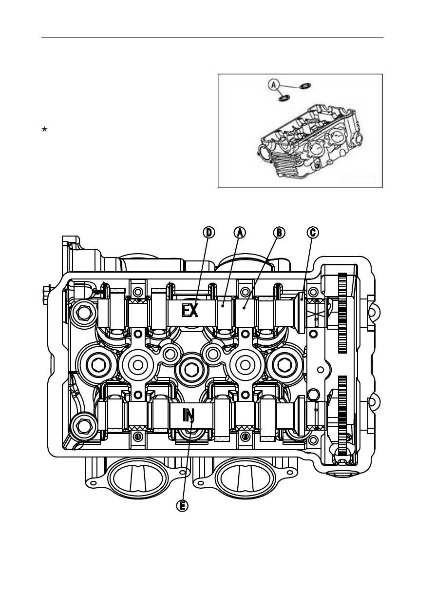
Camshaft Installation

● Be sure to install the following parts.
   Plug Hole Gaskets [A]


● Apply  molybdenum  disulfide  oil  solution  to  all  


  cams [A] journals [B] and thrust blocks [C] with 


   × marks.
    If  a  new  camshaft  is  to  be  used,  apply  a  thin  


   coat of molyb-denum disulfide grease to the cam 


   surfaces.

NOTE

○ 

The exhaust camshaft has a  EX mark [D] 

   and the inlet camshaft has a 2 412 IN mark [E].  
   Be careful not to mix up these shafts.

EX

A

B

C

D

E

IN

-------------------------------------------------------------------------------------------------------------------------------------------------------------

5-16 ENGINE TOP END 

Camshaft/Timing Chain

 Pull the tension side (exhaust side) of the chain 

   taut to install the chain.

 Engage the camshaft chain with the camshaft 

   sprockets so that the timing marks on the 
   sprockets are positioned as shown.

 Using a wrench on the crankshaft rotation bolt, 

   turn thecrankshaft clockwise until the 2/T mark 
   line [A] on the timing rotor is aligned with the 
   notch [B] in the edge of the upper hole [C] in the 
   clutch cover.

 If the clutch cover is removed, perform 

   the next procedure.

 Using a wrench on the crankshaft rotation bolt, 

   turn the crankshaft clockwise until the 1/T mark 
   line [A] on the timing rotor is aligned with the 
   wating surface [B] of the crankcase halves.

 The timing marks must be aligned with 

   the cylinder head upper surface [C].
   EX Mark [D] (between #1 pin and #2 pin)
  IN Mark [E] (between #31 pin and #32 pin)


#1   Pin [F]

    #2   Pin [G]
    #31 Pin [H]
    #32 Pin [J]

-------------------------------------------------------------------------------------------------------------------------------------------------------------

ENGINE TOP END 5-17

Camshaft/Timing Chain

NOTE

 The exhaust cap has a "EX" mark [A] and the 

    inlet cap has a "IN" mark [B]. Be careful not to 
    mix up these caps.

 First tighten all the camshaft cap bolts evenly to 

   seat the camshaft in place, then tighten all bolts 
   following the speci

fi

 ed tightening sequence.


 Torque-Camshaft Cap Bolts (1 < 12)

        12 N·m (1.2 kgf·m, 106 in·Ib)

 Installation:

   Camshaft Chain Tensioner (see Camshaft Chain 
   Tensioner Installation)  
   Cylinder Head Cover (see Cylinder Head Cover 
   Installation)

Camshaft and Sprocket Assembly

 The inlet and exhaust sprockets are identical.

 Install the sprockets so that the marked ("IN" and 

   "EX") side faces to the right side.


CAUTION

Inlet sprocket must use "IN" marked bolts 
holes [A].Exhaust sprocket must use "EX" 
marked bolts holes [B].

 Apply a non-permanent locking agent to the  

   camshaft sprockets bolts and tighten them.


 Torque-Camshaft Shaft Sprockets 

   Bolts: 15 N·m (1.5 kgf·m, 11 ft·Ib)

   If a new camshaft is to be used, apply a thin coat 
    of molybdenum disul

fi

 de to the cam surfaces.

-------------------------------------------------------------------------------------------------------------------------------------------------------------

5-18 ENGINE TOP END 

Camshaft/Timing chain

Camshaft, Camshaft Cap Wear

 Remove:

   Camshaft Caps (see Camshaft Removal)

 Retighten camshaft cap and measure hole  

   diameter of camshaft cap <A>,<B>,<C>.


  Torque: Camshaft cap bolt 12N.m

   Hole diameter of camshaft cap
   Standard : 24.00~24.021mm
   Service Limit: 24.05mm

   If out of service limit, replace new cylinder  
   head.

 Measure camshaft journal diameter. 


Diameter of Camshaft Journal Standard :  

   23.950~23.972mm
   Service Limit : 23.920mm

   If the camshaft journal diameter is less than the  
   service limit, replace the camshaft with a new 
   one and measure the clearance again. If the  
   clearance still remains out of the limit, replace 
   the cylinder head unit.


 Camshaft Journal, Camshaft Cap Clearance

   Standard: 0.028~0.071mm
   Service Limit : 0.13mm


Camshaft run-out 

 Remove the camshaft (see Camshaft Removal).

If the runout exceeds the service limit, replace 

   the shaft.

A

B

C

-------------------------------------------------------------------------------------------------------------------------------------------------------------

ENGINE TOP END 5-19

Camshaft/Timing chain

 Set the camshaft in a camshaft alignment jig or 

   on V blocks.

 Measure runout with a dial gauge at the speci

fi

 ed  

   place as shown.


   Camshaft Runout
   Standard: Less than 0.02mm
       Service limit: 0.04mm

Camshaft wear

 Remove the camshaft (see Camshaft Removal).

 Measure the height [A] of each cam with a 

   micrometer.
   If the cams are worn down past the service limit,  
   replace the camshaft.

    Cam Height
     EX : 35.843~35.957mm
     IN :  36.543~36.657mm
    Service Limit
     EX :35.74mm     
      IN :36.44mm

Camshaft Chain Removal

 Split the crankcase (see Crankcase Splitting in 

    the Crankshaft/Transmission chapter).

-------------------------------------------------------------------------------------------------------------------------------------------------------------

5-20 ENGINE TOP END 

Cylinder head 

Cylinder Compression Measurement

                         NOTE


Use the battery which is fully charged.

 Warm up the engine thoroughly.

 Stop the engine.

 Remove

   Fuel Tank (see Fuel Tank Removal in the Fuel 
   System (EFI) chapter)
   Air Cleaner Housing (see Air Cleaner Housing  
   Removal in the Fuel System (EFI) chapter)
   Ignition Coils (see Ignition Coil together with   
   Spark Plug Cap) Removal in the Electrical 
   System chapter) Spark Plugs (see Spark Plug  
   Replacement in the Periodic Maintenance 
   chapter) 


 Owner’s Tool - Spark Plug Wrench 16mm

 Attach the compression gauge [A] and adapter [B]  


fi

 rmly into the spark plug hole.

   Using the starter motor, turn the engine over with  
  the throttle fully open until the compression  
  gauge stops rising; the compression is the 
   highest reading obtainable.


Special tools: Compression Gauge, 20kgf/    

   cm

2

-------------------------------------------------------------------------------------------------------------------------------------------------------------

ENGINE TOP END 5-21

Cylinder head

Problem

Diagnosis

Countermeasures (Action)

Cylinder compression 
is higher than usable 
range

Carbon accumulation on piston and in 
combustion chamber possibly due to 
damaged valve stem oil seal and/or 
damaged piston oil rings (This may be 
indicated by white exhaust smoke).

Remove the carbon deposits 
and replace damaged parts if 
necessary.

Incorrect cylinder head 
gasket thickness

Replace the gasket with a standard 
part.

Cylinder compression is 
lower than usable range

Gas leakage around cylinder head

Replace damaged gasket and 
check cylinder head warp.

Bad condition of valve seating

Repair if necessary.

Incorrect valve clearance

Adjust the valve clearance.

Incorrect piston/cylinder clearance

Replace the piston and/or cylinder.

Piston seizure

Inspect the cylinder and replace/
repair the cylinder and/or piston 
asnecessary.

Bad condition of piston ring and/or 
piston ring grooves

Replace the piston and/or the 
piston rings.

Cylinder Head Removal

  Remove:

    Exhaust Pipes (see Exhaust Pipe Removal)
    Cylinder Head Cover (see Cylinder Head Cover 
    Removal)
    Camshafts (see Camshaft Removal)
    Throttle Body Assy (see Throttle Body Assy  
    Removal in the Fuel System (EFI) chapter)
    Intake manifold
    Water Hose
    Water Temperature Sensor Connector
    Front Camshaft Chain Guide

 Firstly remove the 4 pcs of M6 cylinder head 

    bolts and M6 cylinder bolts [A].

 Secondly, remove the M8 bolts [B].

 Thirdly, remove the M10 nut [C].

 Finally, remove the M10 bolts [D].

-------------------------------------------------------------------------------------------------------------------------------------------------------------

5-22 ENGINE TOP END 

Cylinder head 

Cylinder head installation

NOTE


The camshaft cap is machined with the cylinder 

   head,so if a new cylinder head is installed, use    
   the cap that is supplied with the new head.

 Install a new cylinder head gasket [A] and dowel 

   pins [B]

 Apply molybdenum disulfide oil solution [A] to 

  both sides of washers and the threads of bolts 
   and nut.

   M10 Cylinder Head Bolts [B] 
   M10 Cylinder Nut [C]
   M8 Cylinder Bolt [D]

Torque - Cylinder head bolt (M10):
First:  25N·m
Final:  
Used Cylinder Head Bolts: 49 N·m
New Cylinder Head Bolts: 54 N·m
Cylinder Nut(M10): 49 N·m

-------------------------------------------------------------------------------------------------------------------------------------------------------------

ENGINE TOP END 5-23

Cylinder head 

Tighten the M6 cylinder head bolts and M6 

  cylinder bolts [A].


 Torque - Cylinder Head Bolts (M6):  

     12 N·m(1.2 kgf·m, 106 in·Ib)
     Cylinder Bolts (M6): 
     12 N·m (1.2 kgf·m, 106 in·Ib)

 Install the front camshaft chain guide [A].

 Insert the end [B] of front camshaft chain guide 

    into the hollow on the lower crankcase half.

 Install the removed parts (see appropriate 

    chapters).

Cylinder Head Warp

 Clean the cylinder head.

 Lay a straightedge across the lower surface of the 

   cylinder head at several positions.

 Use a thickness gauge [A] to measure the space 

   between the straightedge [B] and the head.


 Cylinder Head Warp

   Standard:
   Service Limit:  0.05 mm (0.002 in.)

  If the cylinder head is warped more than the 
   service limit, replace it.

If the cylinder head is warped less than the 

   service limit, repair the head by rubbing the lower   
  surface on emery paper secured to a surface 
   plate (

fi

 rst No. 200, then No.400).

-------------------------------------------------------------------------------------------------------------------------------------------------------------

5-24 ENGINE TOP END 

Valves

Valve Clearance Inspection

 Refer to the Valve Clearance Inspection in the  

    Periodic Maintenance chapter.

Valve Clearance Adjustment

 Refer to the Valve Clearance Adjustment in the   

   Periodic Maintenance chapter.

Valve Removal

 Remove cylinder head (see Cylinder Head 

   Removal).

 Remove the valve lifter and shim Mark and 

   record the valve lifter and shim locations so they 
   can be installed in their original positions.

 Using the valve spring compressor assembly, 

   remove the valve.


Special Tools -Valve  Spring  Compressor  

   Assembly  [A]:
   Valve Spring Compressor Adapter,   [B]:

Valve Installation

 Replace the oil seal with a new one.

 Apply engine oil to the oil seal lip. Apply a thin 

   coat of molybdenum disul

fi

 de grease to the valve 

   stem before valve installation.

 Install the springs so that the closed coil end 

   faces downwards (the side painted in green faces 
   upwards).

   Valve[A]                    Valve spring[E]
   Valve oil seal[B]        Side Painted [F]
   Spring seat[C]           Retainer[G]
   Closed coil end[D]     Split Keepers[H]


-------------------------------------------------------------------------------------------------------------------------------------------------------------

ENGINE TOP END 5-25

Valves

Valve Guide Removal

 Remove:

   Valve (see Valve Removal)
   Oil Seal
   Spring Seat

 Heat the area around the valve guide to 120 < 

   150

O

C (248< 302

O

F), and hammer lightly on the 

   valve guide arbor [A] to remove the guide from 
   the top of the head.


CAUTION

Do not heat the cylinder head with a torch. 
This will warp the cylinder head. Soak the 
cylinder head in oil and heat 
the oil.

Special Tool -  Valve Guide Arbor, 

Φ

 4.5

Valve Guide Installation


Apply engine oil to the valve guide outer  

   surface before installation.


Heat the area around the valve guide hole to  

   about 120 <150 

O

C (248 < 302 

O

F).


Drive the valve guide in from the top of the 

    head using the valve guide arbor. The 
    

fl

 ange stops the guide from going in too far.

    Special Tool -  Valve Guide Arbor, 

Φ

 4.5


Wait until the cylinder head cools down and then 

    ream the valve guide with the valve guide reamer 
    [A] even if the old guide is reused.

-------------------------------------------------------------------------------------------------------------------------------------------------------------

5-26 ENGINE TOP END 

Valves


Turn the reamer in a clockwise direction 

   until the reamer turns freely in the guide. Never 
   turn the reamer counter-clockwise or it will be 
   dulled.

 Once the guides are reamed they must be 

   cleaned thoroughly.


Special tool - Valve Guide Reamer 

Φ

 4.5

Valve-to-Guide Clearance Measurement

 (Wobble Method)

 Insert a new valve [A] into the guide [B] and 

   set a dial gauge against the stem perpendicular 
   to it as close as possible to the cylinder head 
   mating surface.

 Move the stem back and forth [C] to measure 

   valve/valve guide clearance.

 Repeat the measurement in a direction at 

   a right angle to the 

fi

 rst.


NOTE


The reading is not actual valve/valve guide 

   clearance because the measuring point is 
   above the guide.

 Valve/Valve guide clearance
 Standard     
     EX:  0.07~ 0.14mm
     IN:  0.02~ 0.08mm
 Service limit 
     EX:  0.27mm 
     IN:  0.22mm

-------------------------------------------------------------------------------------------------------------------------------------------------------------

ENGINE TOP END 5-27

Valves

Valve Seat Inspection

 Remove the valve (see Valve Removal).

 Check the valve seating surface [A] between the   

   valve [B] and valve seat [C]

 Measure the outside diameter [D] of the seating 

   pattern on the valve seat.
  If the outside diameter is too large or too small, 
   repair the seat (see Valve Seat Repair).

 Valve Seating Surface Outside Diameter
      EX:    27.6 ~ 27.7mm
      IN:      32.6 ~32.7mm


Measure the seat width [E] of the portion 

   where there is no build-up carbon (white portion)
   of the valve seat with a vernier caliper. 
  If the width is too wide [G], too narrow [H] or  
  uneven [J], repair the seat (see Valve Seat 
   Repair).


Valve Seating Surface Width

     EX:    0.5 ~1.0mm
     IN:    0.5 ~1.0 mm

Valve Seat Repair

 Repair the valve seat with the valve seat 

   cutters [A].


 Special Tools - 

       Valve Seat Cutter Holder Bar [C]:
       Valve Seat Cutter Holder 

Φ

 4.5 [B]: 


-------------------------------------------------------------------------------------------------------------------------------------------------------------

5-28 ENGINE TOP END 

Cylinder Removal

 Remove:

   Cylinder Head (see Cylinder Head Removal)
   Front Engine Mounting Bolts (Both Side) [A] (see  
   Engine Removal in the Engine Removal/
   Installation chapter) 
   Front Engine Brackets (Both Side) [B] (see 
   Engine Removal in the Engine Removal/ 
   Installation chapter) 
   Cylinder [C]

Cylinder installation


 NOTE


If a new cylinder is used, use new piston ring.

 Install the dowel pins [A] and new cylinder gasket  

   [B].


 The piston ring openings must be positioned as 

    shown in the 

fi

 gure. The openings of the oil ring 

    steel rails must be about 30 < 40?of angle from 
    the opening of the top ring.

 Top Ring [A]

   Second Ring [B]
   Oil Ring Steel Rails [C] 
   Oil Ring Expander [D] 
   Hollow [E]
   30 < 40

[F]


-------------------------------------------------------------------------------------------------------------------------------------------------------------

ENGINE TOP END 5-29

Cylinder/Pistons

 Apply molybdenum disul

fi

 de oil solution to the 

   cylinder bore, piston rings and piston.

 Prepare two auxiliary head bolts with their head 

   cut.

 Install the two bolts [A] diagonally in the 

   crankcase.

 Position the crankshaft so that all the piston   

   heads are almost level.

 Install the cylinder block. Insert the piston rings 

    with your thumbs.

Piston Removal

 Remove the cylinder (see Cylinder Removal).

 Place a clean cloth under the pistons and remove 

  the piston pin snap ring [A] from the outside of 
   each piston.

 Remove the piston pins.


Special tool :

   Piston Pin Puller [A]
   Piston Pin Puller Adapter [D]

 Remove pistons.

 Carefully spread the ring opening with your 

   thumbs and then push up on the opposite side of 
   the ring [A] to remove it.

 Remove the 3-piece oil ring with your thumbs in  

   the same manner.

-------------------------------------------------------------------------------------------------------------------------------------------------------------

5-30 ENGINE TOP END 

Cylinder/Pistons

Piston installation


Install the oil ring expander [A] in the bottom 

    piston ring groove so the ends [B] butt together.

  Install the oil ring steel rails, one above the 

    expander and one below it.


NOTE


Do not mix up the top [A] and second [C] ring.

 Install the top ring [A] so that the "R" mark 

   [B] faces up.

 Install the second ring [C]so that the "RN" mark 

    [D] faces up.


NOTE


If a new piston is used, use new piston ring.

 Install the piston with its marking hollow facing 

    forward.

 Fit a new piston pin snap ring into the side of the 

   piston so that the ring opening [A] does not   
   coincide with the slit [B] of the piston pin hole.

 Install piston pin.

 Use same way to install the other piston pin ring.

 Apply molybdenum disul

fi

 de oil solution to the 

   piston pins and piston journals.
   When installing the piston pin snap ring, compress 
   it only enough to install it and no more.

CAUTION

Do not reuse snap rings, as removal weakens 
and deforms them. They could fall out and 
score the cylinder wall.

-------------------------------------------------------------------------------------------------------------------------------------------------------------


Content      ..     18      19      20      21     ..