CFMoto motorcycle CF650NK. Service Manual - part 18


  Index      Manuals     CFMoto motorcycle CF650NK. Service Manual


Search            copyright infringement  


Content      ..     16      17      18      19     ..


CFMoto motorcycle CF650NK. Service Manual - part 18


4-2 COOLING SYSTEM

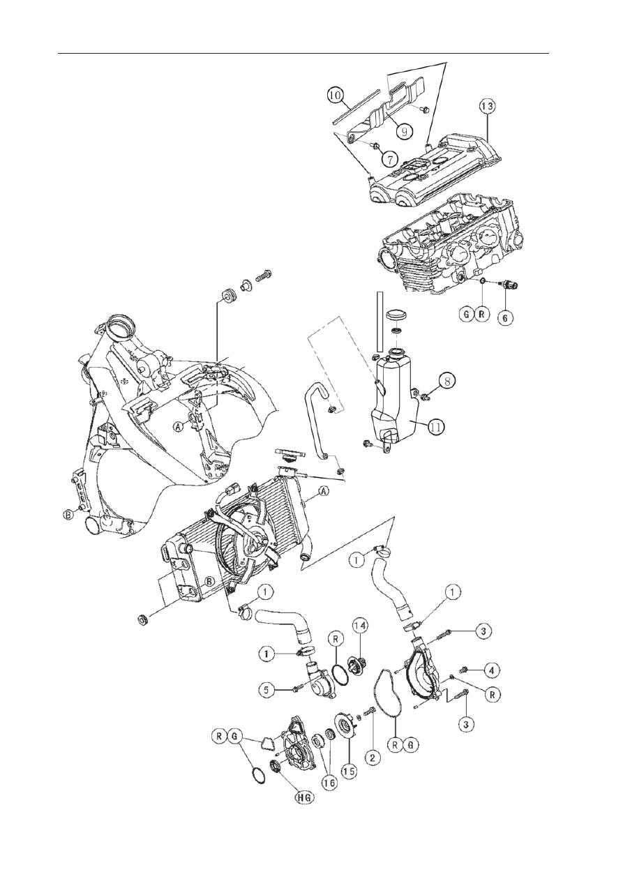
Exploded View
-------------------------------------------------------------------------------------------------------------------------------------------------------------

COOLING SYSTEM 4-3

Exploded View

No.

Fastener

Torque

Remarks

N·m

kgf·m

ft·lb

1

Radiator Hose Clamp Screws

2.0

0.20

17 in·lb

2

Water Pump Impeller Bolt

9.8

1.0

87 in·lb

3

Water Pump Cover Bolts

9.8

1.0

87 in·lb

4

Water Pump Drain Bolt

7.0

0.70

62 in·lb

5

Thermostat Housing Bolts

9.8

1.0

87 in·lb

6

Coolant Temperature Sensor

12

1.2

106 in·lb

7

Baf

fl

 e Plate Bolts

5.9

0.60

52 in·lb

L

8

Baf

fl

 e Plate Bolts

5.9

0.60

52 in·lb

9.   Fairing
10.   Seal Plate
11. Reserve 

Tank

12.   Baf

fl

 e Plate

13.   Cylinder Head Cover
14.   Thermostat
15.  Water Pump Impeller
16.   Mechanical Seal
G:   Apply grease.
HG:  Apply high-temperature grease.
L:   Apply a non-permanent locking agent.
R: Replacement 

Parts

-------------------------------------------------------------------------------------------------------------------------------------------------------------

4-4 COOLING SYSTEM

Coolant Flow Chart

Hot Coolant
Cold Coolant

-------------------------------------------------------------------------------------------------------------------------------------------------------------

COOLING SYSTEM 4-5

Coolant Flow Chart

Permanent type antifreeze is used as a coolant to protect the cooling system from rust and corrosion.
When the engine starts, the water pump turns and the coolant circulates.
The thermostat is a wax pellet type which opens or closes with coolant temperature changes. The
thermostat continuously changes its valve opening to keep the coolant temperature at the proper level.
When coolant temperature is below 80.5 ~ 83.5°C (177 ~ 182°F), the thermostat closes so that the
coolant 

fl

 ow is restricted through the air bleeder hole, causing the engine to warm up more quickly.

When coolant temperature is more than 80.5 ~ 83.5°C, the thermostat opens and the coolant 

fl

 ows.

When the coolant temperature goes up beyond 93 ~ 103°C (199 ~ 217°F), the radiator fan relay
conducts to operate the radiator fan. The radiator fan draws air through the radiator core when there
is not suf

fi

 cient air 

fl

 ow such as at low speeds. This increases up the cooling action of the radiator.

When the temperature is below 91°C (196°F) ~ temperature less than ON temperature, the fan relay
opens and the radiator fan stops.
In this way, this system controls the engine temperature within narrow limits where the engine operates
most ef

fi

 ciently even if the engine load varies.

The system is pressurized by the radiator cap to suppress boiling and the resultant air bubbles
which can cause engine overheating. As the engine warms up, the coolant in the radiator and the
water jacket expands. The excess coolant 

fl

 ows through the radiator cap and hose to the reserve tank

to be stored there temporarily. Conversely, as the engine cools down, the coolant in the radiator and
the water jacket contracts, and the stored coolant 

fl

 ows back to the radiator from the reserve tank.

The radiator cap has two valves. One is a pressure valve which holds the pressure in the system
when the engine is running. When the pressure exceeds 112.3 ~ 141.7 kPa (1.15 ~ 1.45 kgf/cm²,
16.3 ~ 20.5 psi), the pressure valve opens and releases the pressure to the reserve tank. As soon
as pressure escapes, the valve closes, and keeps the pressure at 112.3 ~ 141.7 kPa (1.15 ~ 1.45
kgf/cm², 16.3 ~ 20.5 psi). When the engine cools down, another small valve (vacuum valve) in the
cap opens. As the coolant cools, the coolant contracts to form a vacuum in the system. The vacuum
valve opens and allows the coolant from the reserve tank to enter the radiator.

-------------------------------------------------------------------------------------------------------------------------------------------------------------

4-6 COOLING SYSTEM

Specifi cations

Item

Standard

Coolant Provided when Shipping

Type (Recommended)

Color
Mixed Ratio
Freezing Point
Total Amount

Permanent type of antifreeze (soft water and ethylene 
glycol plus corrosion and rust inhibitor chemicals for 
aluminum engines and radiators)
Green
Soft water 50%, coolant 50%
-35°C (-31°F)
1.2 L (1.3 US qt) (reserve tank full level, including radiator
and engine)

Radiator Cap
Relief Pressure

112.3 ~ 141.7 kPa (1.15 ~ 1.45 kgf/cm², 16.3 ~ 20.5 psi)

Thermostat
Valve Opening Temperature
Valve Full Opening Lift

80.5 ~ 83.5°C (177 ~ 182°F)
8 mm (0.31 in.) or more at 95°C (203°F)

-------------------------------------------------------------------------------------------------------------------------------------------------------------

COOLING SYSTEM 4-7

Special Tools

Bearing Driver Set

Oil Seal Driver

-------------------------------------------------------------------------------------------------------------------------------------------------------------

4-8 COOLING SYSTEM

Coolant

Coolant Deterioration Inspection 

 Remove the right center fairing (see Center 

   Fairing Removal in the Frame chapter).

 Visually inspect the coolant [A] in the reserve 

   tank.
   If whitish cotton-like wafts are observed, 
   aluminum parts in the cooling system are 
   corroded. If the coolant is brown, iron or steel 
   parts are rusting. In either case, 

fl

 ush the cooling 

   system.
   If the coolant gives off an abnormal smell, check 
   for a cooling system leak. It may be caused by 
   exhaust gas leaking into the cooling system.

Coolant Level Inspection 

 Refer to the Coolant Level in the Periodic  

   Maintenance chapter.

Coolant Draining 

 Refer to the Coolant Change in the Periodic 

   Maintenance chapter.

Coolant Filling 

 Refer to the Coolant Change in the Periodic 

   Maintenance chapter.

Pressure Testing 

 Remove the reserve tank (see Coolant Change 

   in the Periodic Maintenance chapter).

 Remove the radiator cap, and install a cooling 

   system pressure tester [A] on the 

fi

 ller neck [B].

NOTE

 Wet the cap sealing surfaces with water or 

   coolant to prevent pressure leaks.

 Build up pressure in the system carefully until the 

   pressure reaches 141.7 kPa (1.45 kgf/cm², 20.5 
   psi).

CAUTION

During pressure testing, do not exceed the 
pressure for which the system is designed. 
The maximum pressure is 141.7 kPa (1.45 kgf/
cm², 20.5 psi).

 Watch the gauge for at least 6 seconds.

   If the pressure holds steady, the system is all 
   right.
   If the pressure drops and no external source is 
   found, check for internal leaks. Droplets in the 
   engine oil indicate internal leakage. Check the 
   cylinder head gasket and the water pump. 

 Remove the pressure tester, replenish the 

   coolant, and install the radiator cap.

-------------------------------------------------------------------------------------------------------------------------------------------------------------

COOLING SYSTEM 4-9

Coolant

Cooling System Flushing

  Over a period of time, the cooling system 
accumulates rust, scale, and lime in the water 
jacket and radiator. When this accumulation is 
suspected or observed, 

fl

 ush the cooling system. If 

this accumulation is not removed, it will clog
up the water passage and considerable reduce the 
ef

fi

 ciency of the cooling system. 

 Drain the cooling system (see Coolant Change in 

   the Periodic Maintenance chapter). 

 Fill the cooling system with fresh water mixed 

   with a 

fl

 ushing compound.

CAUTION

Do not use a flushing compound which is 
harmful to the aluminum engine and radiator. 
Carefully follow the instructions supplied by 
the manufacturer of the
cleaning product.

 Warm up the engine, and run it at normal 

   operating temperature for about ten minutes. 

 Stop the engine, and drain the cooling system. 

 Fill the system with fresh water. 

 Warm up the engine and drain the system. 

 Repeat the previous two steps once more. 

 Fill the system with a permanent type coolant 

   and bleed the air from the system (see Coolant 
   Change in the Periodic Maintenance chapter).

Coolant Reserve Tank Removal/Installation 

 The coolant reserve tank is removed and 

   installed during coolant change (see Coolant 
   Change in the Periodic Maintenance chapter).

-------------------------------------------------------------------------------------------------------------------------------------------------------------

4-10 COOLING SYSTEM

Water Pump

Water Pump Removal

 Drain the coolant (see Coolant Change in the 

   Periodic Maintenance chapter). 

 Loosen the clamp and remove the radiator hose 

   [A] from the water pump cover [B]. 

 Remove the water pump cover bolts [C].

 Shift the transmission into 1st gear.

 While applying the rear brake, remove the water 

   pump impeller bolt [A]. 

 Remove:

   Impeller [B]
   Water Pump Housing [C]

Water Pump Installation 

 When installing the water pump impeller bolt, 

   shift the transmission into 1st gear and apply the 
   rear brake. 

 Replace the O-rings [A] on the water pump 

   housing with new ones and apply grease them. 

 Apply high-temperature grease to the lips of the   

   water pump housing oil seal [B].

 Be sure that the dowel pin [A] is in position. 

 Install the water pump housing. 

 Tighten:

   Torque - Water Pump Impeller Bolt: 9.8 N·m 
   (1.0 kgf·m, 87 in·lb)

 Replace the O-ring [A] on the water pump cover 

   with a new one and grease it.

-------------------------------------------------------------------------------------------------------------------------------------------------------------

COOLING SYSTEM 4-11

Water Pump

 Install the water pump cover, being careful of the 

   two dowel pins [A].

   Torque - Water Pump Cover Bolts: 9.8 N·m (1.0 
   kgf·m, 87 in·lb)

Mechanical Seal Inspection


 Visually inspect the mechanical seal.

   If any one of the parts is damaged, replace the 
   mechanical seal as a unit.

 The sealing seat and rubber seal may be 

   removed easily by hand.
   Impeller Sealing Seat Surface [A]
   Rubber Seal [B]
   Mechanical Seal Diaphragm [C]

Water Pump Housing Disassembly

CAUTION

Be careful not to damage the sealing surface 
of the mechanical seal.

 Take the oil seal [A] out of the housing [B] with a 

    hook [C].

 Press the mechanical seal [A] out of the housing 

   with a bearing driver [B].
   

Special Tool - Bearing Driver Set

Water Pump Housing Assembly 

 Apply high-temperature grease [A] to the new oil 

   seal [B]. 

 Press the oil seal into the housing with a bearing 

   driver so that the seal surface is 

fl

 ush [C] with the 

   end of the hole. 

 Press the new mechanical seal into the housing 

   with the oil seal driver [D] until its 

fl

 ange [E] 

   touches the surface [F] of the housing.
 

  Special Tool - Oil Seal Driver

-------------------------------------------------------------------------------------------------------------------------------------------------------------

4-12 COOLING SYSTEM

Water Pump

Impeller Assembly 

 Clean the sliding surface of the mechanical seal  

   with a high-

fl

 ash point solvent, and apply a little  

   coolant to the sliding surface to give the 
   mechanical seal initial lubrication.

 Apply coolant to the surfaces of the rubber seal [A] 

   and sealing seat [B], and install the rubber seal 
   and sealing seat into the impeller by pressing 
   them by hand until the seat stops at the bottom of 
   the hole.

Pump Impeller Inspection 

 Visually check the impeller [A].

   If the surface is corroded, or if the blades are 
   damaged,replace the impeller (see Water Pump 
   Removal).

-------------------------------------------------------------------------------------------------------------------------------------------------------------

COOLING SYSTEM 4-13

Radiator

Radiator and Radiator Fan Removal 

 Drain the coolant (see Coolant Change in the 

   Periodic Maintenance chapter). 

 Remove:

   Center Fairings (see Center Fairing in the Frame 
   chapter)
   Reserve Tank (see Coolant Change in the  
   PeriodicMaintenance chapter)
   Radiator Fan Motor Connector [A] (Disconnect)
   Radiator Hose Clamp Screw [B] (Loosen)

 Loosen:

   Radiator Hose Clamp Screw [A] 

 Remove:

   Radiator Bolt [B]

 Pull [A] the radiator [B] toward the left, noting the 

   baf

fl

 e plate [C] on the cylinder head cover.

CAUTION

Do not touch the radiator core. This could 
damage the radiator fi ns, resulting in loss of 
cooling effi ciency.

 If necessary, remove:

   Radiator Fan Mounting Bolts [A]
   Radiator Fan [B]

-------------------------------------------------------------------------------------------------------------------------------------------------------------

4-14 COOLING SYSTEM

Radiator

Radiator and Radiator Fan Installation

 Install the grommets [A] so that its large side 

   faces the front. 

 Install the radiator [B] to the frame.

 Align [C] the projection on the frame with the hole 

   on the radiator.

 Tighten the radiator bolt [D].

 Note the baf

fl

 e plate on the cylinder head cover 

   when installing the radiator.

 Position the radiator hose clamp screws [E] as 

   shown.

Radiator Inspection 

 Check the radiator core.

   If there are obstructions to air 

fl

 ow, remove them.

   If the corrugated 

fi

 ns [A] are deformed, carefully

   straighten them.
   If the air passages of the radiator core are  
   blocked more than 20% by unremovable 
   obstructions or irreparably deformed 

fi

 ns, replace 

   the radiator with a new one.

CAUTION

When cleaning the radiator with steam cleaner, 
be careful of the following to prevent radiator 
damage: Keep the steam gun [A] away more 
than 0.5 m (1.6 ft) [B] from the radiator core. 
Hold the steam gun perpendicular [C] (not 
oblique [D]) to the core surface. Run the 
steam gun, following the core fi n direction.

Radiator Cap Inspection 

 Remove:

   Reserve Tank (see Coolant Change in the  
   Periodic Maintenance chapter)
   Radiator Cap 

 Check the condition of the bottom [A] and top [B] 

   valve seals and valve spring [C].
   If any one of them shows visible damage, replace   

-------------------------------------------------------------------------------------------------------------------------------------------------------------

COOLING SYSTEM 4-15

Radiator

 Install the cap [A] on a cooling system pressure 

   tester [B].

NOTE


Wet the cap sealing surfaces with water or 

   coolant to prevent pressure leaks.

 Watching the pressure gauge, pump the pressure 

   tester to build up the pressure until the relief 
   valve opens: the gauge needle 

fl

 icks downward. 

   Stop pumping and measure leak time at once. 
   The relief valve must open within the speci

fi

 ed 

   range in the table below and the gauge hand
   must remain within the same range at least 6 
   seconds.

   Radiator Cap Relief Pressure
   Standard: 112.3 ~ 141.7 kPa (1.15 ~ 1.45 kgf/
   cm², 16.3 ~ 20.5 psi)

   If the cap can not hold the speci

fi

 ed pressure or 

   if it holds too much pressure, replace it with a 
   new one.

Radiator Filler Neck Inspection 

 Remove the reserve tank (see Coolant Change 

   in the Periodic Maintenance chapter). 

 Remove the radiator cap. 

 Check the radiator 

fi

 ller neck for signs of 

   damage. 

 Check the condition of the top and bottom 

   sealing seats [A] in the 

fi

 ller neck. They must be 

   smooth and clean for the radiator cap to function 
   properly.

-------------------------------------------------------------------------------------------------------------------------------------------------------------

4-16 COOLING SYSTEM

Thermostat

Thermostat Removal 

 Drain the coolant (see Coolant Change in the 

   Periodic Maintenance chapter). 

 Remove:

   Left Center Fairing (see Center Fairing Removal 
   in the Frame chapter)
   Thermostat Hosing Bolts [A]
   Thermostat Hosing [B]

 Pull the thermostat [A] out of the cylinder head.

Thermostat Installation 

 Install the thermostat [A] in the cylinder head 

   so that the air bleeder hole [B] is on top. 

 Install a new O-ring into the housing and apply 

   grease it. 

 Tighten:

   Torque - Thermostat Hosing Bolts: 9.8 N·m 
   (1.0 kgf·m, 87 in·lb)

 Fill the radiator with coolant (see Coolant Change 

   in the Periodic Maintenance chapter).

Thermostat Inspection 

 Remove the thermostat, and inspect the 

   thermostat valve [A] at room temperature.
   If the valve is open, replace the thermostat with a 
   new one

-------------------------------------------------------------------------------------------------------------------------------------------------------------

COOLING SYSTEM 4-17

Thermostat

 To check valve opening temperature, suspend 

    the thermostat [A] in a container of water and 
    raise the temperature of the water.

 The thermostat must be completely submerged  

   and must not touch the container sides or bottom. 
   Suspend an accurate thermometer [B] in the 
   water so that the heat sensitive portions [C] are 
   located in almost the same depth. It must not 
   touch the container, either.
   If the measurement is out of the speci

fi

 ed range, 

   replace the thermostat with a new one.

   Thermostat Valve Opening Temperature
   80.5 ~ 83.5°C (177 ~ 182°F)

-------------------------------------------------------------------------------------------------------------------------------------------------------------


Content      ..     16      17      18      19     ..