CFMoto motorcycle CF650NK. Service Manual - part 16
 

  Index      Manuals     CFMoto motorcycle CF650NK. Service Manual


Search            copyright infringement  


Content      ..     14      15      16      17     ..


CFMoto motorcycle CF650NK. Service Manual - part 16


FUEL SYSTEM (EFI) 3-49

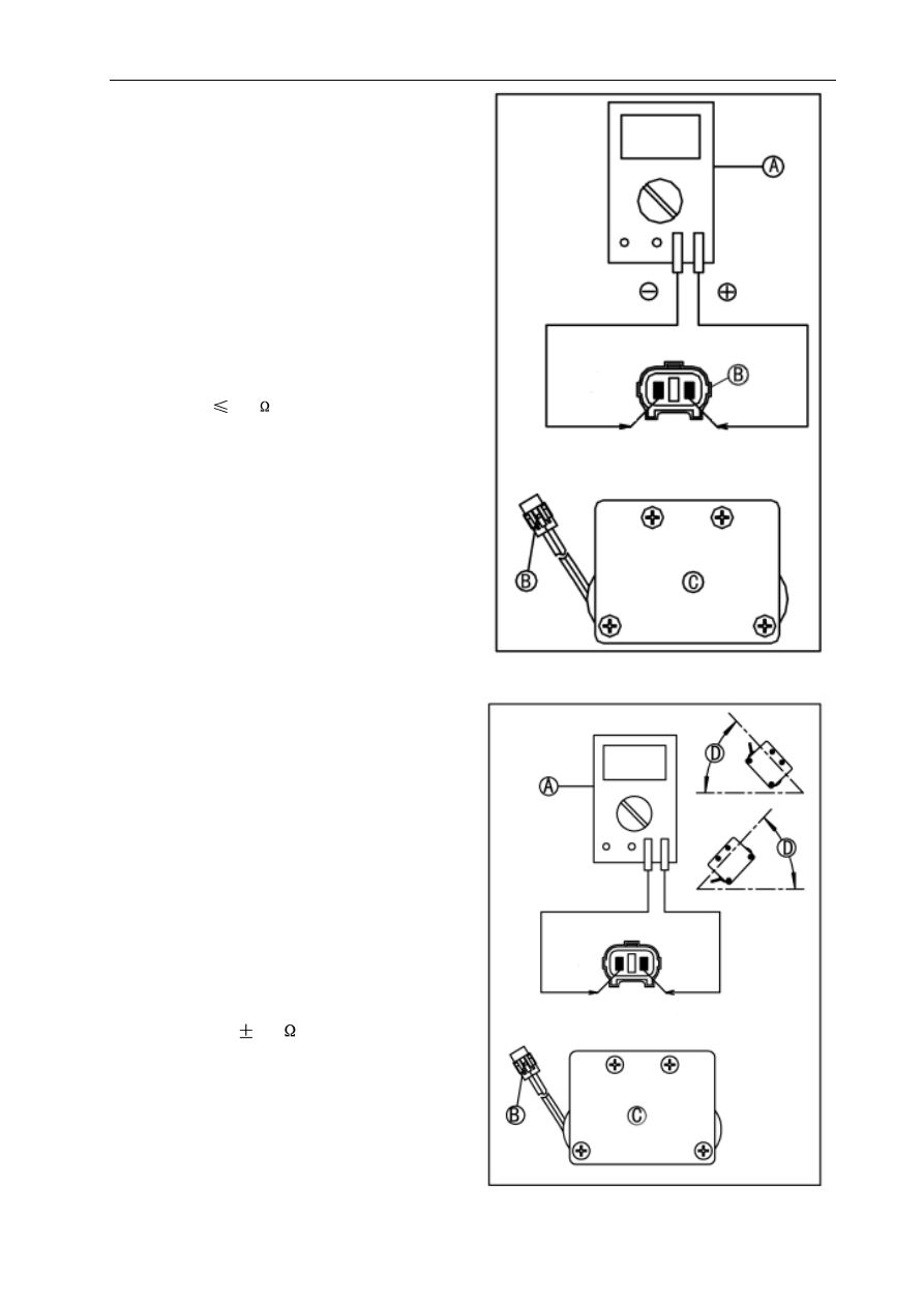
   Roll-over Sensor Resistance Inspection(when

   not tilted)

 Remove roll-over sensor [C] (see Roll-over Sensor

   Removal/Installation).

 Disconnect roll-over sensor connector [B].

 Connect hand tester [A] to connector[B] and mea-

   sure the resistance.

   Roll-over Sensor Output Resistance:

   Standard:R

0.5

   Roll-over sensor is placed as showin in the right

   figure.

   Roll-over Resistance Inspection (when not

   tilted)

 Remove roll-over sensor [C] (see Roll-over Sensor

   Removal/Installation).

 Disconnect roll-over sensor connector [B].

 Connect hand tester [A] to connector [B] and mea-

   sure the resistance.

 Tilt the sensor  40~50

o

 or more [C] right or left, then

   and measure the output resistance.

Roll-over Sensor Output Resistance

Standard:R=62

5k

(20°C)

Sensor  tilted 


40~50

o

 or more [C] right or

left

   Roll-over Sensor

-------------------------------------------------------------------------------------------------------------------------------------------------------------

3-50 FUEL SYSTEM (EFI)

Oxygen Sensor

Oxygen Sensor Removal/Installation

Oxygen Removal

 Disconnect connector[A] and remove oxygen sen-

   sor [B].

Oxygen Sensor Installation

 Connect oxygen sensor [B] and connector[A].

Torque: 60N

m

2 N

m

Never drop the sensor [B], especially on a

hard surface. Such a shock to the part can

damage it. Do not touch the portion [A] of the

sensor, otherwise, the oil residue on your

hand may contaminate  the sensor and cause

performance degeneration.

WARNING

!

-------------------------------------------------------------------------------------------------------------------------------------------------------------

FUEL SYSTEM (EFI) 3-51

Oxygen Sensor
Oxygen Sensor Inspection

 Disconnect the oxygen sensor connector [A] of  one

   cylinder.

 Place the transmission in neutral.

 Start the engine and throughly warm it up, then have

   the engine run at more than 5000rpm.

 Measure oxygen sensor output volatage using hand

   tester[B].

Disconnect the oxygen sensor connector

   [A] of one cylinder.

 Place the transmission in neutral.

 Start the engine and let it idle.


Standard: about 0.8V

   Oxygen Sensor Output Voltage

   Oxygen Sensor Output Voltage

   Cylinder 1:

   Meter(+)

B lead [C]

   Meter(-)

Grlead [D]

   Cylinder 2:

   Meter(+)

B lead  [C]

   Meter(-)

Gr lead [D]

-------------------------------------------------------------------------------------------------------------------------------------------------------------

3-52 FUEL SYSTEM (EFI)

 Measure oxygen sensor output voltage with hand

   tester [B].

   Oxygen Sensor Output Voltage:

   Cylinder 1:

   Meter(+)

B lead [C]

   Meter(-)

Gr lead [D]

Oxygen Sensor

   Standard: about 0.1V

   Oxygen Sensor Output Voltage:

   Cylinder 2:

 Remove the hose [B].

   Meter(+)

B lead [C]

   Meter(-)

Gr lead [D]

-------------------------------------------------------------------------------------------------------------------------------------------------------------

FUEL SYSTEM (EFI) 3-53

Ignition Coil

Ignition Coil Removal/Installation

Stick Coil Input Voltage Inspection

Be sure the battery is fully charged.

 NOTE

 Turn the iignition switch OFF.

 Remove the fuel tank.

Ignition Coil Input Voltage:

Ignition coil 1:

Meter (+)

B/Y lead [C]

Meter (-)

   Ground

Standard: about 12 V DC

Ignition coil 2:

Meter (+)

B/Y lead [C]

Meter (+)

Ground

Standard: about 12 V DC

 Remove the air filter.

 Remove the ignition switch connector [A].

 Connect a hand tester [B] as shown.

G

N

I

N

R

A

W

Never drop the sensor, especially on a hard

surface. Such a shock to the part can damage it.

 Measure the input voltage to each primary winding

   of the ignition coils with the engine stopped, and
   with the connectors joined.

 Turn the ignition switch ON. Measure the ignition

   coil input voltage during fuel pump working time.

!

-------------------------------------------------------------------------------------------------------------------------------------------------------------

3-54 FUEL SYSTEM (EFI)

Ignition Coil

Ignition Coil Circuit

1. Main Fuse
2. Battery
3. ECU
4. Ignition Switch
5. Fuse Box
6. Engine Stop Switch
7. Fuel Pump Relay
8. Ignition Coil 1
9. Ignition Coil 2

-------------------------------------------------------------------------------------------------------------------------------------------------------------

FUEL SYSTEM (EFI) 3-55

Turn the ignition SW on.

Does the light (LED) go on?

Does the light (LED) go off after 5 seconds?

The light (LED) shortly blinks 

15 times after it goes on for 5 

seconds.

Alerts owner to have the dealer 

do the maintenance of EFI 

Does the light (LED) keep on for 10 seconds 

then start to blink?

Allow the engine to idle.

Turn the ignition SW off.

Repair or replace the meter or wiring.

Check the light (LED) and the wiring.

The light (LED) and EFI system are considered 

to be normal.

EFI has trouble(s).

Turn the ignition SW off 

and end the inspection 

(go to self-diagnosis).

Ask the rider if the problem

occurs again. 

EFI is normal.

Replace the ECU.

No

NG

Yes

Good

Yes

No

No

Yes

Yes

No

-------------------------------------------------------------------------------------------------------------------------------------------------------------

3-56 FUEL SYSTEM (EFI)

FI Indicator Light

FI Indicator Light Inspection

 Remove the meter unit (see Meter Unit Removal in

   the Electrical System chapter).

 Using two auxiliary leads, supply battery power to

   the FI indicator light (LED) [A].

 Battery [B] 12 V.

   Battery (+) terminal

Meter lead terminal 1

   Battery (-)terminal

Meter lead terminal 13

   Criterion: The light (LED) should light.

If the light does not go on, replace the meter unit

   (see Meter Unit Removal/Installation in the Electri-
   cal Sys- tem chapter).

FI Indicator Light Circuit

1. Main Fuse                                                               2: Battery
3. ECU                                                                       4. Ignition Switch
5. Fuse Box                                                                6. Engine Stop Switch
7. Meter Unit

-------------------------------------------------------------------------------------------------------------------------------------------------------------

FUEL SYSTEM (EFI) 3-57

ECU
ECU Removal/Installation

ECU Removal

 Remove rear seat (see Seat Removal in the Frame

   chapter)

 ECU [A] and the harness.

 Disconnect the ECU lead connectors.

ECU Installation:

 Fit the ECU unit and connect the lead connectors.

ECU Power Supply Inspection

 Visually inspect the terminals [A] of the ECU

   connectors.

If the connector is clogged with mud or dust, blow it

   off with compressed air.

Replace the main harness if the terminals of the

   main harness connectors are cracked, bent, or oth-
   erwise damaged.

Replace the ECU if the terminals of the ECU con-

   nectors are cracked, bent, or otherwise damaged.

With the ECU connectors [A] connected, check the

   following ground lead for continuity with the ignition
   switch OFF, using a tester and needle adapter set.
   Battery 

[B]

   Tester [C]

ECU Grounding Inspection

  Terminal 2 (G/B), 17 (G)

Battery (-)

   terminal: 0 

   Engine ground

 Battery (-) terminal: 0 

If no continuity, check the connector, the engine

   ground lead, or main harness, and repair or replace
   them if nec- essary.

N

O

I

T

U

A

C

Never drop the sensor, especially on a hard

surface. Such a shock to the part can damage it.

-------------------------------------------------------------------------------------------------------------------------------------------------------------

3-58 FUEL SYSTEM (EFI)

ECU Power Source Inspection

   Meter Connections:
   Between Terminal 1 (Br/L) and Battery (+) Terminal
   Between Terminal 18 (Br/B) and Battery (+) Termi-
   nal
   Ignition Switch OFF:
   Terminal 1 (Br/L) and Battery (-) Terminal:
   Battery Voltage (12.8 V or more)
   Terminal 18 (Br/B) and Battery (-) Terminal:
   Ignition Switch ON, Engine Stop Switch ON:
   Both: Battery Voltage (12.8 V or more)

If the meter does not read as specified, check the

   following.
   Main Fuse 30 A (see Fuse Inspection in the Electri-
   cal System chapter)
   ECU Fuse 15 A (see Fuse Inspection in the Electri-
   cal System chapter)
   ECU Main Relay (see Relay Circuit Inspection in
   the Electrical System chapter)
   Power Source Wiring (see wiring diagram below)

If the inspection checks good, the ECU is damaged.

   Replace the ECU (see ECU Removal/Installation).
   The ECU itself cannot be checked or serviced.

ECU

ECU Power Source Inspection

 Check the ECU power source voltage with a hand

   tester [A].

-------------------------------------------------------------------------------------------------------------------------------------------------------------

FUEL SYSTEM (EFI) 3-59

ECU Circuit Diagram

1. Ignition Switch
2. Fuse Box
3. Engine Stop Switch
4. ECU
5. Main Fuse
6. Battery

ECU

-------------------------------------------------------------------------------------------------------------------------------------------------------------

3-60 FUEL SYSTEM (EFI)

Fuel Line

Fuel Pressure Inspection

 NOTE

This inspection can determine which trouble the EFI

   system has, mechanical or electrical trouble.

It is preferable to measure the fuel pressure while

   running the motorcycle just when trouble occurred

   in order to know symptom well.

Be sure the battery is fully charged.

Fuel Pressure Measurement

 Remove the fuel tank (see Fuel Tank Removal).

 Be sure to place a piece of cloth around the fuel

   hose joint and the delivery pipe.

 Insert a minus screw driver [A] into the slit on the

   joint lock [B].

 Turn the driver to disconnect the joint lock.

 Install the fuel pressure gauge adapter [A] and fuel

   hoses between the fuel pump outlet pipe [B] and
   the delivery pipe [C].

 Connect the pressure gauge [D] to the fuel pressure

   gauge adapter.

  E: Fuel Tank  D: Fuel Pressure Gauuge F: Joint
 

 Connect the joints and ensure no leaks.


 Turn the ignition switch ON. Fuel pump will turn for

    3 seconds, then stop.

Be prepared for fuel spillage; any spilled fuel

must be completely wiped up immediately.

When the fuel hose is disconnected, fuel spills

out from the hose and the pipe because of re-

sidual pressure. Cover the hose connection with

a piece of clean cloth to prevent fuel spillage.

G

N

I

N

R

A

W

G

N

I

N

R

A

W

Do not try to start the engine with the fuel

hoses disconnected.

Do not drive the fuel pump without the fuel in

the fuel tank.

G

N

I

N

R

A

W

!

!

!

-------------------------------------------------------------------------------------------------------------------------------------------------------------

FUEL SYSTEM (EFI) 3-61

Fuel Line

Fuel Pressure Inspection

 Measure the fuel pressure with the engine stopped.

NOTE

The gauge needle will fluctuate. Read the pressure

  at the average of the maximum and minimum

   indications

.

If the fuel pressure is normal, the fuel circulation

   system (fuel pump, pressure regulator, and fuel
   passage) is no faults. Check the EFI electronic con-
   trol system (injectors, sensors, crankshaft sensor,
   and ECU).

Fuel Pressure

Right after Ignition Switch ON, with pump

running:

Standard:

330 kPa (0.33 MPa)

After 3 seconds from Ignition Switch ON, with

pump stopped:

Standard:

265 kPa (0.265 MPa)

The system should hold the residual pressure

about 30 seconds.

If the fuel pressure is much lower than specified,

   check the following.
   Fuel Line Leakage
    Fuel Pump Operation (check the sound of the pump)
   Amount of Fuel Flow (see Fuel Flow Rate
   Inspection)

If the fuel pressure is much higher than specified,

   check the following.
   Delivery Pipe Clogging
   Injector Clogging
   Fuel pressure regulator damage

-------------------------------------------------------------------------------------------------------------------------------------------------------------

3-62 FUEL SYSTEM (EFI)

Fuel Pump

Fuel Flow Rate Inspection

NOTE

Be sure the battery is fully charged.

Wipe off spilled out fuel immediately.Be sure

to hold the measuring cylinder vertical.

Gasoline is extremely flammable and can be

explosive under certain conditions. Make sure the

area is well-ventilated and free from any source

of flame or sparks; this includes any appliance

with a pilot light. Do not smoke. Turn the ignition

switch OFF. Be prepared for fuel spillage; any

spilled fuel must be completely wiped up

immediately.

G

N

I

N

R

A

W

 Turn the ignition switch, and engine stop switch OFF.

 Wait until the engine cools down.

 Prepare a plastic hose of the inside diameter 7.5

   mm (0.30 in.) and a measuring cylinder.

 Remove the fuel tank bolt (see Fuel Tank Removal).

 Open the fuel tank cap [A] to lower the pressure in

   the tank.

   Be prepared for fuel spillage; any spilled fuel

   must be completely wiped up immediately.

   When the fuel hose is disconnected, fuel spills

   out from the hose and the pipe because of re-

   sidual pressure. Cover the hose connection with

   a piece of clean cloth to prevent fuel spillage.

G

N

I

N

R

A

W

 Connect the plastic hose [A] to the fuel pump outlet

   pipe.

 Secure the plastic hose with a clamp [B].

 Run the other side of the plastic hose into the mea-

   suring cylinder [C].

G

N

I

N

R

A

W

!

!

!

-------------------------------------------------------------------------------------------------------------------------------------------------------------

FUEL SYSTEM (EFI) 3-63

Fuel Pump

Fuel Flow Rate Inspection

G

N

I

N

R

A

W

Do not drive the fuel pump without the fuel in

the fuel tank.

 Measure the discharge for 3 seconds with the plas-

   tic hose filled with fuel.

 Repeat this operation several times.

Amount of Fuel Flow

Standard:

60 mL or more for 3 seconds

If the fuel flow is much less than the specified, check

   the battery condition (see Charging Condition In
  spection in the Electrical System chapter). If the
  battery is good, replace the fuel pump (see Fuel
   Pump Removal/Installation).

 After inspection, install the fuel tank (see Fuel Tank

   Installation).

 Start the engine and check for fuel leakage.

!

-------------------------------------------------------------------------------------------------------------------------------------------------------------

3-64 FUEL SYSTEM (EFI)

Fuel Pump

Fuel Pump Removal/Installation

Fuel Pump Removal

Never drop the fuel pump, especially on a

hard surface. Such a shock to the pump can

damage it.

   Remove:
   Fuel Pump Bolts [A].
   Fuel Pump [B].
   Replace fuel pump gasket [C] if damaged.

G

N

I

N

R

A

W

Gasoline is extremely flammable and can be

explo- sive under certain conditions. Make

sure the area is well-ventilated and free from

any source of flame or sparks; this includes

any appliance with a pilot light. Do not smoke.

Turn the ignition switch OFF. Disconnect the

battery (-) terminal.To make fuel spillage

minimum, draw the fuel out from the fuel tank

when the engine is cold. Be prepared for fuel

spillage; any spilled fuel must be completely

wiped up immediately.

G

N

I

N

R

A

W

 Draw the fuel out from the fuel tank with a commer-

   cially available electric pump.

 Remove the fuel tank (see Fuel Tank Removal).

 Be careful of fuel spillage from the fuel tank since

   fuel still remains in the fuel tank and fuel pump. Plug
   the fuel pipe of the fuel tank.

 Turn the fuel tank upside down.

Do not pull the lead of the fuel pump.  If they

are pulled, the lead terminals may be

damaged.

N

O

I

T

U

A

C

!

!

-------------------------------------------------------------------------------------------------------------------------------------------------------------


Content      ..     14      15      16      17     ..