содержание .. 16 17 18 19 ..
FTB-2 и FTB-2 Pro. Руководство пользователя - часть 18
Preparing for Automation
Configuring DCOM Access to Your Unit
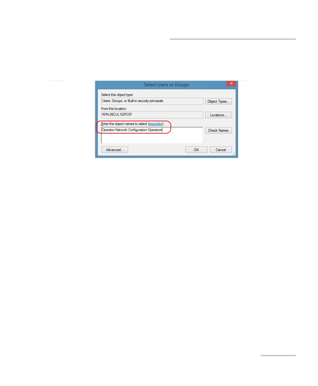
17. In the Select Users or Groups dialog box, under Enter the object
names to select, type the name of the user to whom you want to give
access permissions for remote access.
18. Tap OK.
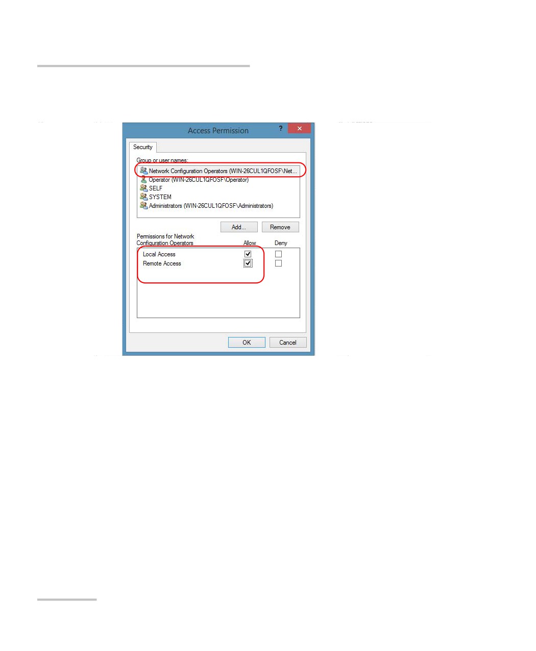
19. In the Access Permission dialog box, select a user.
FTB-2 and FTB-2 Pro
263
Preparing for Automation
Configuring DCOM Access to Your Unit
20. To allow this user to access the unit remotely, select Allow for both
permission choices.
Note: You can also deny connection permission for specific users.
21. Repeat steps 19 and 20 for each newly added user.
22. Tap OK to close the Access Permission dialog box.
23. Tap OK to close the EXFO KernosHost Properties dialog box.
24. Restart your unit.
The EXFO IcSCPIAccess Class component, located on your unit, can
now be accessed with DCOM.
264
FTB-2 and FTB-2 Pro
Preparing for Automation
Configuring DCOM Access to Your Unit
Enabling DCOM on Client Computer
Note: To run DCOMCNFG.EXE, you need Administrator access rights.
If you want to subscribe to EXFO IcSCPIAccess Class component events,
you need to set security parameters on the client computer.
To enable DCOM on the client computer:
1. Start Windows, on the taskbar, click Start (Start button (
) under
Windows 8.1) and select Run.
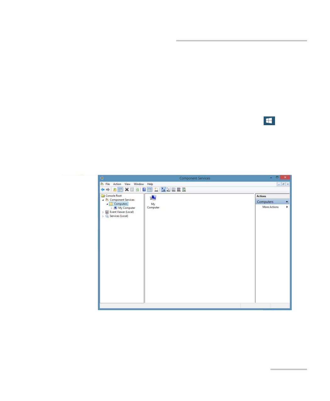
2. In the Open box, type “DCOMCNFG.EXE” and tap OK.
3. In the Component Services dialog box, select: Console Root >
Component Services > Computers to show available computers.
FTB-2 and FTB-2 Pro
265
Preparing for Automation
Configuring DCOM Access to Your Unit
4. Right-click My Computer, and then select Properties.
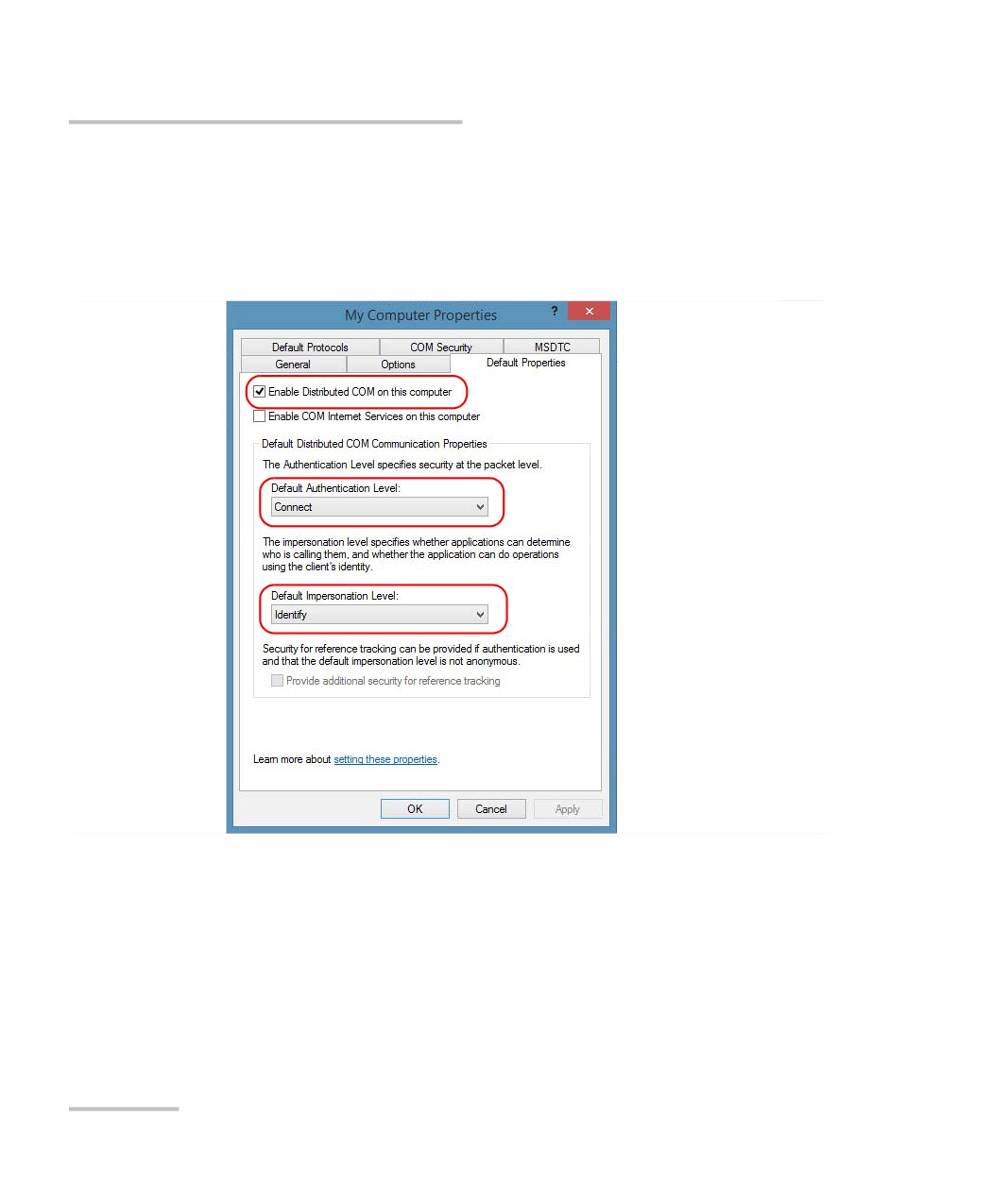
5. In the My Computer Properties dialog box, tap the Default Properties
tab.
6. Select Enable Distributed COM on this computer.
7. Under Default Distributed COM Communication Properties, in the
Default Authentication Level list, select Connect.
8. In the Default Impersonation Level list, select Identify.
9. Tap Apply.
266
FTB-2 and FTB-2 Pro
Preparing for Automation
Configuring DCOM Access to Your Unit
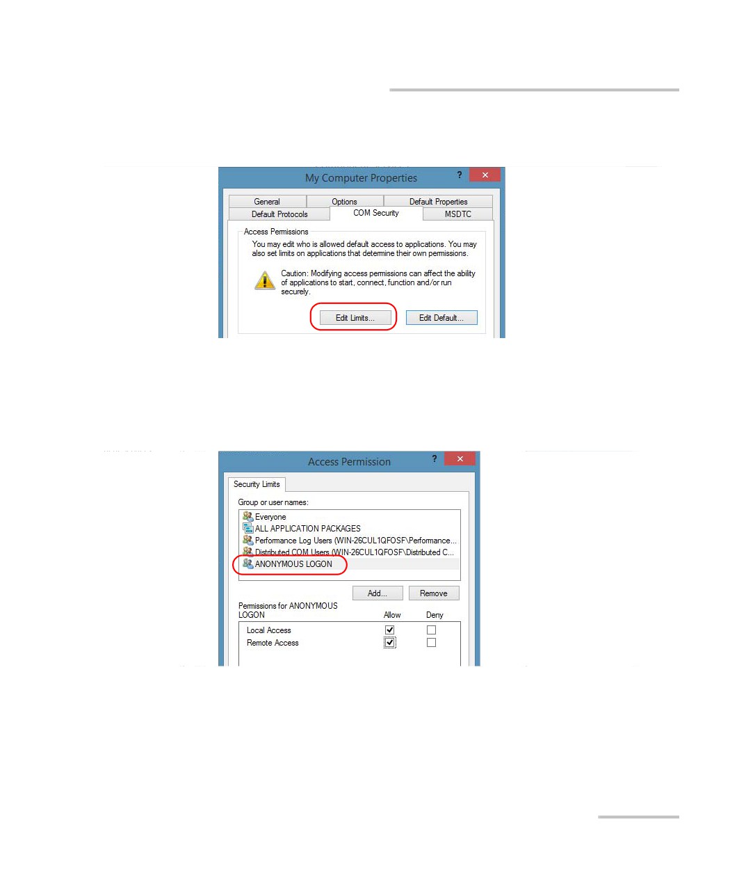
10. Tap the COM Security tab and, under Access Permissions, tap Edit
Limits.
11. In the Access Permission dialog box, ensure that, for ANONYMOUS
LOGON, local and remote accesses are allowed.
If ANONYMOUS LOGON is not listed under Group or user names, tap
Add to add it.
For more information on enabling events with DCOM, refer to
AppId Key in MSDN Documentation.
FTB-2 and FTB-2 Pro
267
Preparing for Automation
Configuring DCOM Access to Your Unit
Disabling DCOM Access to Your Unit
Note: To change the DCOM access to your unit, you need Administrator access
rights.
If you no longer want client computers to access your unit using DCOM,
you can disable this access.
To disable DCOM access to your unit:
1. From the main window, tap the System Settings button.
2. Tap Control Panel.
3. Tap System and Security > Administrative Tools.
4. Double-tap Component Services.
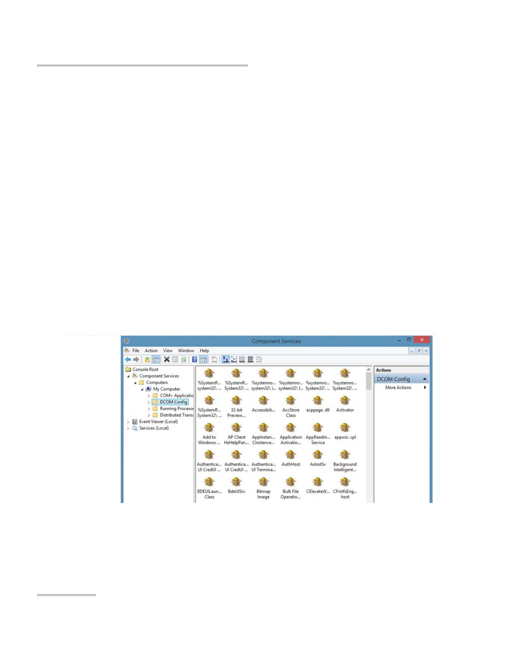
5. From the Component Services window, select: Console Root >
Component Services > Computers > My Computer > DCOM Config
to show the contents of the DCOM Config folder.
6. From DCOM Config, right-click EXFO KernosHost, and select
Properties.
268
FTB-2 and FTB-2 Pro
Preparing for Automation
Configuring DCOM Access to Your Unit
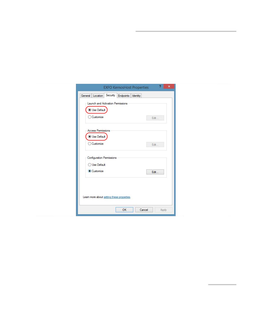
7. In the EXFO KernosHost Properties dialog box, tap the Security tab.
8. Under Launch and Activation Permissions and Access Permissions,
select Use Default.
This ensures the EXFO IcSCPIAccess Class component uses the default
lists instead of the customized lists.
9. Tap OK.
10. Restart your unit.
The EXFO IcSCPIAccess Class component, located on your unit,
cannot be accessed with DCOM.
FTB-2 and FTB-2 Pro
269
Preparing for Automation
Preparing to Control Modules with a Dedicated Application
Preparing to Control Modules with a
Dedicated Application
Some modules come with a dedicated application designed to control
them remotely from a computer. The main characteristic of this application
is that it lets another user control the module exactly as if he had it close at
hand.
To control the module remotely, you must configure it on the unit
containing the module, including a description that can help you identify it.
The user controlling the module from a computer must install the
dedicated application (for more information on the installation, refer to the
application documentation).
The module can be controlled both remotely and locally at the same
time.
You will have to configure your remote control again in the following
cases:
you inserted the module in another slot
you applied changes on applications while the module is not
inserted in its slot.
Note:
Some modules do not support the remote control.
IMPORTANT
If there is a network failure or a problem with your
remotely-controlled module, you can shut down the latter without
closing all the other applications. The local and remote module
session will then be closed.
270
FTB-2 and FTB-2 Pro
Preparing for Automation
Preparing to Control Modules with a Dedicated Application
To activate or deactivate remote control:
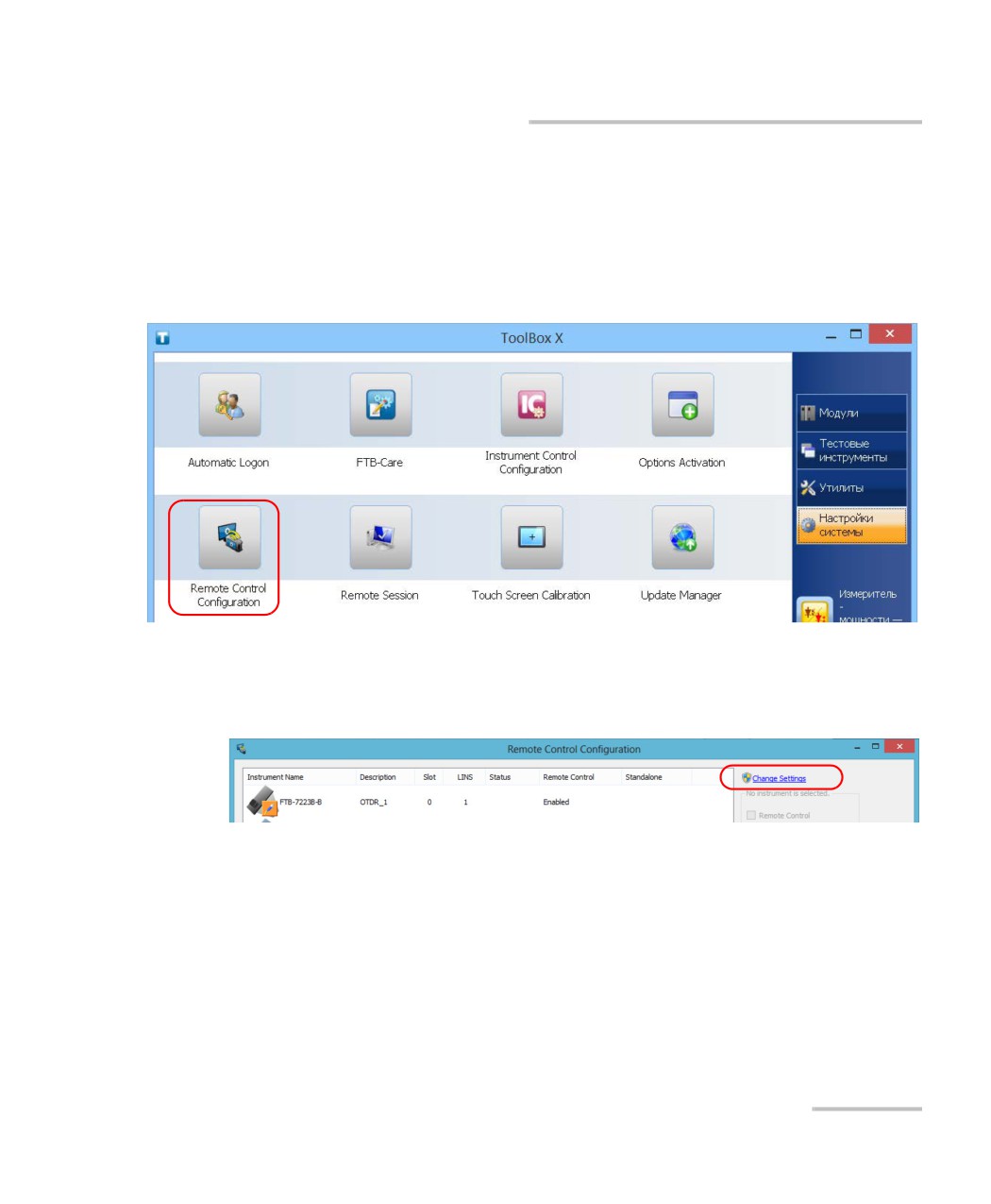
1. From the main window, tap the System Settings button.
2. Tap Remote Control Configuration.
3. If necessary, tap Change settings, and then, when the application
prompts you to authorize the changes to your unit (identified as
“computer”), select Yes.
FTB-2 and FTB-2 Pro
271
Preparing for Automation
Preparing to Control Modules with a Dedicated Application
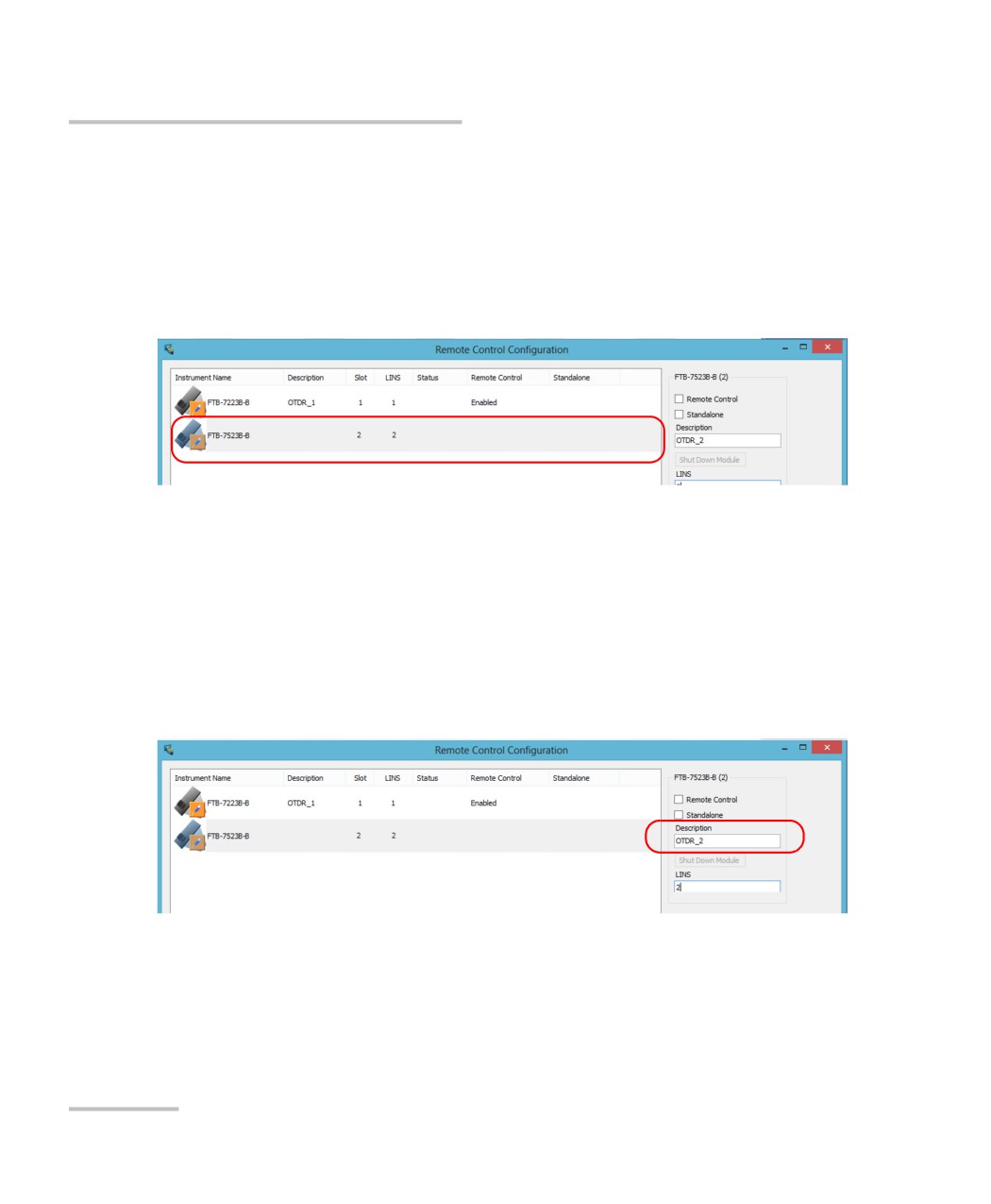
4. From the Remote Control Configuration window you will see all the
inserted modules. Select the module for which you want to have a
remote access.
Note: Modules for which remote control is not supported are identified as
unrecognized.
5. Set the parameters:
Select Remote Control to let another user control the module from
a computer.
Select Standalone to leave the module active even if all users
close their dedicated applications.
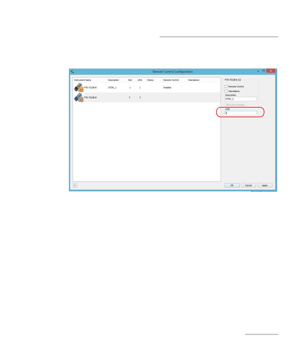
6. If desired, under Description, type a description that will help you
identify the instrument.
Note: You can enter up to 10 characters. The description can correspond to the
test interface ID or to any other short text of your choice.
272
FTB-2 and FTB-2 Pro
Preparing for Automation
Preparing to Control Modules with a Dedicated Application
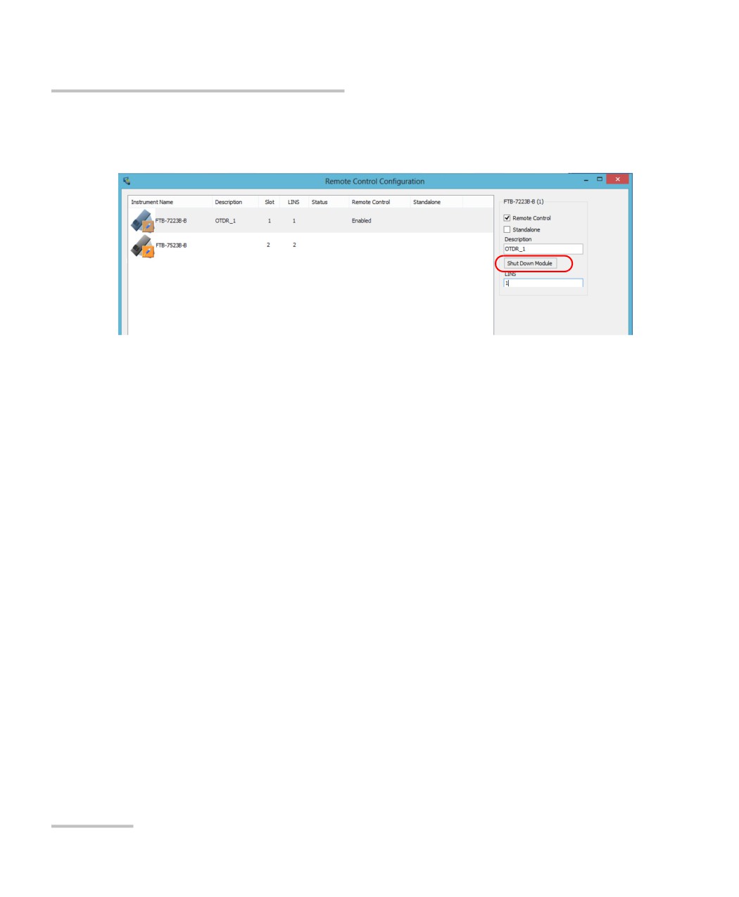
7. If necessary, under LINS, modify the logical instrument number that
you will use to access the instrument remotely.
8. Tap Apply to confirm your changes or OK to apply your changes and
close the window.
Note: This information will be updated the next time you start the module
application and will appear in the title bar if the module application allows
it. Refer to the corresponding module documentation for more details.
FTB-2 and FTB-2 Pro
273
Preparing for Automation
Preparing to Control Modules with a Dedicated Application
To shut down the remotely-controlled module:
Tap Shut Down Module.
274
FTB-2 and FTB-2 Pro
12 Using Your Unit and Modules
in an Automated Test
Environment
EXFO supplies commands that follow the guidelines determined by the
SCPI consortium for all available instruments. EXFO also supplies COM
properties and events allowing you to build your own application.
The present chapter gives you information to help you use the provided
commands as well as COM properties and events to remotely control your
instruments.
If you need information on how to prepare your unit for remote control, see
the corresponding section in this documentation.
Note: To have access to automation features on an FTB-2 unit, you must
purchase the Automation option.
FTB-2 and FTB-2 Pro
275

Using Your Unit and Modules in an Automated Test Environment
Standard Status Data Structure
Standard Status Data Structure
Each device that is physically connected to the remote bus has four status
registers with a structure complying with the IEEE 488.2 standard. These
registers allow the controller to monitor events and get useful information
on the status of the devices it controls.
Standard Event Status Register (ESR)
Standard Event Status Enable Register (ESE)
Status Byte Register (STB)
Service Request Enable Register (SRE)
ESR and ESE
The standard event status register and status enable register information is
presented in the following table.
Bits
Mnemonics
Bit Value
7
Power On (PON)
128
6
User Request (URQ)
64
5
Command Error (CME)
32
4
Execution Error (EXE)
16
3
Device-Dependent Error (DDE)
8
2
Query Error (QYE)
4
1
Not Used (N.U.)
0
0
Operation Complete (OPC)
1
276
FTB-2 and FTB-2 Pro

Using Your Unit and Modules in an Automated Test Environment
Standard Status Data Structure
The following table presents a summary of the possible operations on ESR
and ESE registers.
Register
Read
Write
Clear
ESR
Use *ESR?.
Impossible
Use *CLS.
to write.
Read the register.
ESE
Use *ESE?.
Use *ESE.
Use *ESE with a value equal to 0.
STB and SRE
The status byte register and service request enable register information is
presented in the following table.
Bits
Mnemonics
Bit Value
7
Not Used (N.U.)
0
6
Master Summary Status (MSS)/ Service
64
Request (RQS)
5
Event Summary Bit (ESB)
32
4
Message Available (MAV)
16
3
Not Used (N.U.)
0
2
Error Available (EAV)
4
1
Not Used (N.U.)
0
0
Not Used (N.U.)
0
FTB-2 and FTB-2 Pro
277

Using Your Unit and Modules in an Automated Test Environment
Standard Status Data Structure
The following table presents a summary of the possible operations on STB
and SRE registers.
Register
Read
Write
Clear
STB
Use *STB?.
Impossible to write;
Use *CLS before
the register content is
sending a query (to
Use serial poll (GPIB
only modified when
clear the Event registers
bus sequence that
the Event registers or
and Queues and by the
allows retrieval of the
Queues are modified.
same token clear the
value without
STB register).
interrupting the current
process).
SRE
Use *SRE?.
Use *SRE with a value
Use *SRE with a
equal to 0 to disable
value equal to 0.
the register or with a
At startup, the
value equal to 1 to
register is set to 0.
enable it.
The diagram displayed on the next page is a useful aid in understanding
the general commands and how a service request (SRQ) is generated.
Using a service request, a device notifies the controller that an event
requiring special attention occurred. The controller will then find which
device generated a SRQ (its RQS bit is set) and the causes of it.
278
FTB-2 and FTB-2 Pro
содержание .. 16 17 18 19 ..