SINUMERIK 840D sl. Basesoftware and operating software. Manual (2019) - page 16
Configuration in the side screen
11.4 Adding Run MyScreens configurations to a side screen element
11.4
Adding Run MyScreens configurations to a side screen element
The basis of the procedure that is described in the following as example is a side screen page
with a side screen element. Two Run MyScreens configurations are displayed next to each
other in the side screen element.
Configure a side screen page with a side screen element as described in the following. Assign
two side screen widgets with the respective Run MyScreens configurations to the side screen
element.
Procedure
Expand the "slsidescreen.ini" by the following entries:
[Sidescreen]
PAGE100= name:=RMSPage, implementation:=SlSideScreenPage
● You cannot change the specification for the implementation, "SlSideScreenPage" in this
case.
[Page_RMSPage]
ELEMENT001= name:=RMSElement, implementation:= SlSideScreenElement
● You cannot change the specification for the implementation, "SlSideScreenElement" in this
case.
[Element_RMSElement]
TextId=RMS_ELEMENT_TITLE
TextFile=rmstexts
TextContext=rmstexts
TextContext=rmstexts
WIDGET001= name:=RMSWidget001,
implementation:=sleseasyscreen.SlEsSideScreenWidget
WIDGET002= name:=RMSWidget002,
implementation:=sleseasyscreen.SlEsSideScreenWidget
SINUMERIK Integrate Run MyScreens
298
Programming Manual, 06/2019, A5E40869575B AC
Configuration in the side screen
11.4 Adding Run MyScreens configurations to a side screen element
●
When the SlSideScreenElement implementation is used for the side screen element (see
Section [Page_RMSPage]), the side screen element has a title bar in which a text can be
displayed.
This text is configured with the entries TextId, TextFile and TextContext:
- TextId: Text ID of the text to be displayed
- TextFile: File in which the text is saved
- TextContext: Text context, in which the text is located within this file
A separate file must be provided for each language.
The name of these files is formed according to the following diagram:
<TextFile>_<Sprachsuffix>.ts, e.g. rmstexts_deu.ts for the example above.
If you do not specify a file or a context (TextFile=<empty> and TextContext=<empty>), the
text ID is displayed as text. You can specify any string as the text ID.
The text file (e.g. rmstexts_deu.ts) is structured as follows:
<?xml version="1.0" encoding="utf-8"?>
<!DOCTYPE TS>
<TS>
<context>
<name>rmstexts</name>
<message>
<source>My application</source>
<translation>My Application</translation>
</message>
</context>
</TS>
Store the file in the directory /oem/sinumerik/hmi/lng or /user/sinumerik/hmi/lng. During the
next HMI power-up, the file is converted to the file format that is needed during runtime.
●
You can freely select the names of the widgets assigned to the element, "RMSWidget001"
and "RMSWidget002" in this case.
●
You must not change the widget implementation
"sleseasysscreen.SlEsSideScreenWidget".
[Widget_RMSWidget001]
PROPERTY001= name:=maskPath, type:=QString, value:="mymask001.com"
PROPERTY002= name:=maskName, type:=QString, value:="MyMask001"
[Widget_RMSWidget002]
PROPERTY001= name:=maskPath, type:=QString, value:="mymask002.com"
PROPERTY002= name:=maskName, type:=QString, value:="MyMask002"
● The names of the sections are formed for configuring the side screen widgets by appending
the name of the widget that is to be configured in this section to the prefix "Widget_".
● In the Property maskPath, specify the name of the file that contains the RunMyScreens
configuration, "mymask001.com" or "mymask002.com" in this case.
● In the Property maskName, specify the name of the RunMyScreens mask that is to be
displayed, "MyMask001" or "MyMask002" in this case.
SINUMERIK Integrate Run MyScreens
Programming Manual, 06/2019, A5E40869575B AC
299
Configuration in the side screen
11.5 Notes on carrying out Run MyScreens configurations in the side screen
11.5
Notes on carrying out Run MyScreens configurations in the side
screen
Note the following:
● The functions LS, LM, DLGL, EXIT, EXITLS are not available when carrying out Run
MyScreens configurations in the side screen.
● It is not possible to query the mask size in the LOAD block.
● Texts are always displayed using the font that is used in SINUMERIK Operate with a screen
resolution of 640x480 pixels.
● The configured positions of operator controls are implemented without changes (e.g.
extension).
● The dialog size is adapted automatically.
● If Run MyScreens configurations are carried out in a side screen page, the entire area of the
page is available for the configuration. When carrying out in side screen elements or
widgets, the area available for display is specified by the system depending on the context.
● The header and softkeys cannot be configured.
● All of the debugging and error outputs are sequentially written to the text file
"easyscreen_log.txt". There is no specific identification indicating which configuration a
message comes from.
● The status of a Run MyScreens configuration displayed in the side screen is rejected when
the configuration is faded out.
Note
The integration of Run MyScreens configurations into the side screen can lead to more than
one Run MyScreens configuration being carried out simultaneously. To maintain the functional
capability of the overall system, take note of the additional system load caused as a result of the
hardware used.
SINUMERIK Integrate Run MyScreens
300
Programming Manual, 06/2019, A5E40869575B AC
Configuration in the Display Manager
12
12.1
Displaying Run MyScreens configurations in the Display Manager
The SISideScreenDialog dialog is available to you for displaying Run MyScreens
configurations in the Display Manager. Depending on the space available, this dialog can
display one or more side screen pages (see IM9 Chapter 3.13). Several pages are displayed
next to each other in column format. The available space (width) is evenly divided among the
individual columns. The number of pages to be displayed and their content are configured.
Each page has its own configuration file. The names of these configuration files are specified
during the dialog configuration in the "systemconfiguration.ini" file, in the command line
parameter "cmdline". Behind the parameter identifier "-sidescreen1" is the name of the
configuration file for the first column; behind the parameter identifier "-sidescreen2" is the
name of the configuration file for the second column, etc.
Example
[dialogs]
DLG500= name:=RMSApp,
implementation:=sldmsidescreenapp.SlSideScreenDialog,
process:=SlHmiHost1, preload:=false, cmdline:=“-sidescreen1
rmspage1.ini -sidescreen2 rmspage2.ini -spacing 3”
The instance of the SlSideScreenDialog dialog created in this example has the name RMSApp.
It has 2 pages/columns. The two pages/columns are configured in the files "rmspage1.ini" and
"rmspage2.ini". Between the two columns, there is a distance of 3 pixels.
Note
You can freely select the names of the files with the page configurations, "rmspage1.ini" and
"rmspage2.ini" in this case.
The use of Run MyScreens configurations in the Display Manager is done as described in
Chapter Configuration in the side screen (Page 291). The only difference is that the integration
of the configurations is not done in the file "slsidescreen.ini", but in the respective files provided
for the configuration of the existing pages.
2 variants are available to you for the integration of Run MyScreens configurations into the
Display Manager of SINUMERIK Operate. These are described in the following sections.
SINUMERIK Integrate Run MyScreens
Programming Manual, 06/2019, A5E40869575B AC
301
Configuration in the Display Manager
12.2 Integration in SISideScreenDialog
12.2
Integration in SISideScreenDialog
For the integration of the Run MyScreens configuration, you must create the dialog instance of
SlSideScreenDialog in the file "systemconfiguration.ini" and create the file for integrating the
Run MyScreens configuration.
The following example shows the integration of a Run MyScreens configuration. The Run
MyScreens configuration takes up the entire window of the SlSideScreenDialog dialog, i.e. only
one page/column exists.
Procedure
First, create an instance of the SlSideScreenDialog in the "systemconfiguration.ini" file in
the [dialogs] section. The instance is given the name "RMSApp".
[dialogs]
DLG500= name:=RMSApp,
implementation:=sldmsidescreenapp.SlSideScreenDialog,
process:=SlHmiHost1, preload:=false,
cmdline:=“-sidescreen1 rmsapp.ini”
In the next step, you will configure or integrate the RunMyScreens configuration in the
"rmsapp.ini" file:
[Sidescreen]
PAGE001= name:=RMSPage, implementation:=SlSideScreenPage
● Create a page with the name "RMSPage".
[Page_RMSPage]
ELEMENT001= name:=RMSElement,
implementation:=sleseasyscreen.SlEsSideScreenElement
● You create an element with the name RMSElement on the RMSPage. This element is used
for displaying the Run MyScreens configuration.
[Element_RMSElement]
PROPERTY001= name:=maskPath, type:=QString,
value:="sidescreenmask.com"
PROPERTY002= name:=maskName, type:=QString, value:="Mask"
● In the property maskPath, specify the name of the file that contains the RunMyScreens
configuration, "sidescreenmask.com" in this case.
● In the property maskName, specify the name of the RunMyScreens mask that is to be
displayed, "sidescreenmask.com" in this case.
Store the files "rmsapp.ini" and "systemconfiguration.ini" (see above) in the directory /oem/
sinumerik/hmi/cfg or /user/sinumerik/hmi/cfg.
The Run MyScreens configuration is available after the next HMI power-up.
SINUMERIK Integrate Run MyScreens
302
Programming Manual, 06/2019, A5E40869575B AC
Configuration in the Display Manager
12.3 Integration into SIWidgetsApp
12.3
Integration into SIWidgetsApp
The integration of a Run MyScreens configuration into the SlWidgetsApp application, which is
part of the SIEMENS delivery kit, is described in the following.
Depending on which page/column of the SlWidgetsApp application the Run MyScreens
configuration is to be integrated into, you must expand either the "sldmwidgets1.ini" file or the
"sldmwidgets2.ini" file accordingly.
The following example shows the integration of a Run MyScreens configuration into the left
page/column of the SlWidgetsApp application.
Procedure
Expand the "sldmwidgets1.ini" file as follows:
[Sidescreen]
PAGE001= name:=WidgetsPage, implementation:=SlSideScreenPage
[Page_WidgetsPage]
ELEMENT100= name:=RMSElement,
implementation:=sleseasyscreen.SlEsSideScreenElement
● Create an element with the name "RMSElement" for displaying the Run MyScreens
configuration.
Note
Use a number range ≥ 100 for new elements. This avoids conflicts with the SIEMENS display
elements. The RMSElement is inserted in the WidgetsPage under the SIEMENS elements
according to this numbering.
[Element_RMSElement]
PROPERTY001= name:=maskPath, type:=QString,
value:="sidescreenmask.com"
PROPERTY002= name:=maskName, type:=QString, value:="Mask"
● In the property maskPath, specify the name of the file that contains the RunMyScreens
configuration, "sidescreenmask.com" in this case.
● In the Property maskName, specify the name of the RunMyScreens mask that is to be
displayed, "Mask" in this case.
Save the file "sldmwidgets1.ini" in the directory /oem/sinumerik/hmi/cfg or /user/sinumerik/hmi/
cfg .
The Run MyScreens configuration is available after the next HMI power-up.
SINUMERIK Integrate Run MyScreens
Programming Manual, 06/2019, A5E40869575B AC
303
Configuration in the Display Manager
12.4 Notes on carrying out Run MyScreens configurations in the Display Manager
12.4
Notes on carrying out Run MyScreens configurations in the Display
Manager
Note the following:
● The functions LS, LM, DLGL, EXIT, EXITLS are not available when carrying out Run
MyScreens configurations in the Display Manager.
● It is not possible to query the mask size in the LOAD block.
● Texts are always displayed using the font that is used in SINUMERIK Operate with a screen
resolution of 640x480 pixels.
● The configured positions of operator controls are implemented without changes (e.g.
extension).
● If Run MyScreens configurations are carried out in a side screen page, the entire area of the
page is available for the configuration. When carrying out in side screen elements or
widgets, the area available for display is specified by the system depending on the context.
● All of the debugging and error outputs are sequentially written to the text file
easyscreen_log.txt. There is no specific identification indicating which configuration a
message comes from.
● The status of a Run MyScreens configuration displayed in the Display Manager is rejected
when the configuration is faded out.
Note
The integration of Run MyScreens configurations into the Display Manager can lead to more
than one Run MyScreens configuration being carried out simultaneously. To maintain the
functional capability of the overall system, take note of the additional system load caused as a
result of the hardware used.
SINUMERIK Integrate Run MyScreens
304
Programming Manual, 06/2019, A5E40869575B AC

Reference lists
A
A.1
Lists of start softkeys
A.1.1
List of start softkeys for turning
Program operating area for turning
HSK1
HSK2
HSK3
HSK4
HSK5
HSK6
HSK7
HSK8
Edit
Drilling
Turning
Contour turn-
Milling
Miscellane-
Simulation
NC select
ing
ous
HSK9
HSK10
HSK11
HSK12
HSK13
HSK14
HSK15
HSK16
--
Straight-line
--
--
Measure
Measure tool
OEM
--
circle
workpiece
(only for
ShopTurn)
Turning
The following tables list the possible start softkeys for turning technology. Assignments of
individual start softkeys can differ depending on the particular system. The specified OEM
softkeys are permitted for "Run MyScreens".
programGUIDE (G-Code) start softkeys:
Drilling
Turning
Contour turning
Milling
Miscellaneous
HSK2
HSK3
HSK4
HSK5
HSK6
VSK1
Centering
Stock remov-
Contour
--
Face mill-
Contour
Settings
High
al
ing
speed
settings
VSK2
Drilling ream-
Groove
Stock removal
--
Pocket
Path
Swivel plane
Parallel
ing
axes
VSK3
Deep-hole drill-
Undercut
Stock remov-
--
Multi-edge
Predrilling
Swivel tool
--
ing
al residual ma-
spigot
terial
VSK4
Boring
Thread
Grooving
--
Groove
Pocket
--
--
VSK5
Thread
Parting
Grooving re-
--
Thread
Pocket
--
--
sidual material
milling
res. mat.
VSK6
OEM
--
Plunge-turn-
--
Engraving
Spigot
Subprogram
--
ing
SINUMERIK Integrate Run MyScreens
Programming Manual, 06/2019, A5E40869575B AC
305

Reference lists
A.1 Lists of start softkeys
VSK7
Positions
OEM
Plunge turn-
OEM
OEM
Spigot res.
--
OEM
ing residual
mat.
material
VSK8
Repeat posi-
--
>>
<<
Contour
<<
>>
<<
tion.
milling
ShopTurn start softkeys:
Drilling
Turning
Contour turning
Milling
Miscellaneous
HSK2
HSK3
HSK4
HSK5
HSK6
HSK10
VSK1
Drilling
Stock re-
New contour
--
Face mill-
New con-
Settings
High
Tool
centered
moval
ing
tour
speed set-
tings
VSK2
Centering
Groove
Stock removal
--
Pocket
Path
Swivel
Parallel
Straight line
plane
axes
VSK3
Drilling
Undercut
Stock remov-
--
Multi-edge
Predrilling
Swivel tool
Repeat
Circle center
reaming
al residual
spigot
progr.
point
material
VSK4
Deep-
Thread
Grooving
--
Groove
Pocket
Counter-
--
Circle radius
hole drill-
spindle
ing
VSK5
Thread
Parting
Grooving re-
--
Thread mill-
Pocket
Transfor-
--
Polar
sidual materi-
ing
res. mat.
mations
al
VSK6
OEM
--
Plunge-turn-
--
Engraving
Spigot
Subpro-
--
Approach/
ing
gram
retract
VSK7
Positions
OEM
Plunge turn-
OEM
OEM
Spigot
--
OEM
--
ing residual
res. mat.
material
VSK8
Repeat
--
>>
<<
Contour
<<
>>
<<
--
position.
milling
See also
Defining the start softkey (Page 33)
A.1.2
List of start softkeys for milling
Program operating area when milling
HSK1
HSK2
HSK3
HSK4
HSK5
HSK6
HSK7
HSK8
Edit
Drilling
Milling
Contour mill-
Turning
Miscellane-
Simulation
NC select
ing
(only for G
ous
code)
SINUMERIK Integrate Run MyScreens
306
Programming Manual, 06/2019, A5E40869575B AC
Reference lists
A.1 Lists of start softkeys
HSK9
HSK10
HSK11
HSK12
HSK13
HSK14
HSK15
HSK16
--
Straight-line
--
--
Measure
Measure tool
OEM
--
circle
workpiece
(only for
ShopMill)
Milling
The following tables list the possible start softkeys for milling technology. Assignments of
individual start softkeys can differ depending on the particular system. The specified OEM
softkeys are permitted for "Run MyScreens".
programGUIDE (G-Code) start softkeys:
Drilling
Milling
Contour milling
Turning
Miscellaneous
HSK2
HSK3
HSK4
HSK5
HSK6
VSK1
Centering
Face milling
Contour
--
Stock re-
Contour
Settings
--
moval
VSK2
Drilling ream-
Pocket
Path
--
Groove
Stock re-
Swivel plane
Parallel
ing
moval
axes
VSK3
Deep-hole drill-
Multi-edge
Predrilling
--
Undercut
Stock re-
Swivel tool
--
ing
spigot
moval re-
sidual ma-
terial
VSK4
Boring
Groove
Pocket
--
Thread
Grooving
High speed set-
--
tings
VSK5
Thread
Thread mill-
Pocket res.
--
Parting
Grooving
--
--
ing
mat.
residual
material
VSK6
OEM
Engraving
Spigot
--
--
Plunge-
Subprogram
--
turning
VSK7
Positions
OEM
Spigot res.
OEM
OEM
Plunge
--
OEM
mat.
turning re-
sidual ma-
terial
VSK8
Repeat posi-
--
>>
<<
Contour
<<
>>
<<
tion.
turning
ShopMill start softkeys:
Drilling
Milling
Contour milling
Miscellaneous
Straight line circle
HSK2
HSK3
HSK4
HSK6
HSK10
VSK1
Centering
Face milling
New contour
--
Settings
--
Tool
VSK2
Drilling ream-
Pocket
Path
--
Swivel plane
Parallel axes
Straight line
ing
VSK3
Deep-hole
Multi-edge
Predrilling
--
Swivel tool
Repeat progr.
Circle center point
drilling
spigot
VSK4
Boring
Groove
Pocket
--
High speed set-
--
Circle radius
tings
VSK5
Thread
Thread mill-
Pocket res. mat.
--
Transforma-
--
Helix
ing
tions
SINUMERIK Integrate Run MyScreens
Programming Manual, 06/2019, A5E40869575B AC
307
Reference lists
A.1 Lists of start softkeys
VSK6
OEM
Engraving
Spigot
--
Subprogram
--
Polar
VSK7
Positions
OEM
Spigot res. mat.
OEM
--
OEM
--
VSK8
Repeat posi-
--
>>
<<
>>
<<
--
tion.
SINUMERIK Integrate Run MyScreens
308
Programming Manual, 06/2019, A5E40869575B AC
Reference lists
A.2 List of predefined softkeys
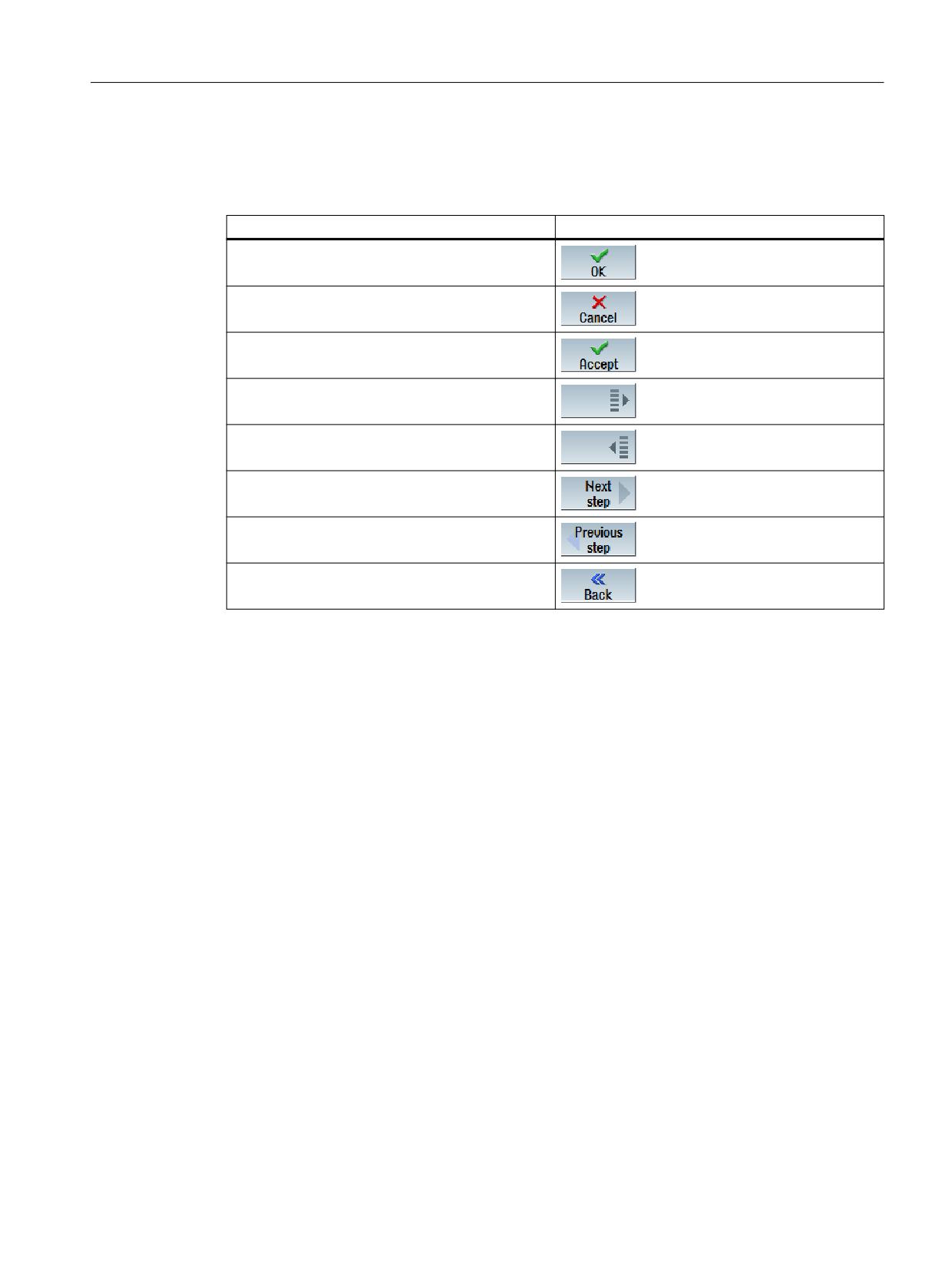
A.2
List of predefined softkeys
Table A-1
Predefined softkeys
Name
Softkey
SOFTKEY_OK
SOFTKEY_CANCEL
SOFTKEY_APPLY
SOFTKEY_MORE
SOFTKEY_BACK
SOFTKEY_ASSISTANT_NEXT
SOFTKEY_ASSISTANT_PREVIOUS
SOFTKEY_NAV_BACK
SINUMERIK Integrate Run MyScreens
Programming Manual, 06/2019, A5E40869575B AC
309
Reference lists
A.3 List of access levels
A.3
List of access levels
The meanings of the different access levels are as follows:
Protection level
Locked by
Area
ac0
Reserved for Siemens
ac1
Password
Machine manufacturer
ac2
Password
Service
ac3
Password
User
ac4
Keyswitch position 3
Programmer, machine setter
ac5
Keyswitch position 2
Qualified operator
ac6
Keyswitch position 1
Trained operator
ac7
Keyswitch position 0
Semi-skilled operator
SINUMERIK Integrate Run MyScreens
310
Programming Manual, 06/2019, A5E40869575B AC
Reference lists
A.4 List of colors
A.4
List of colors
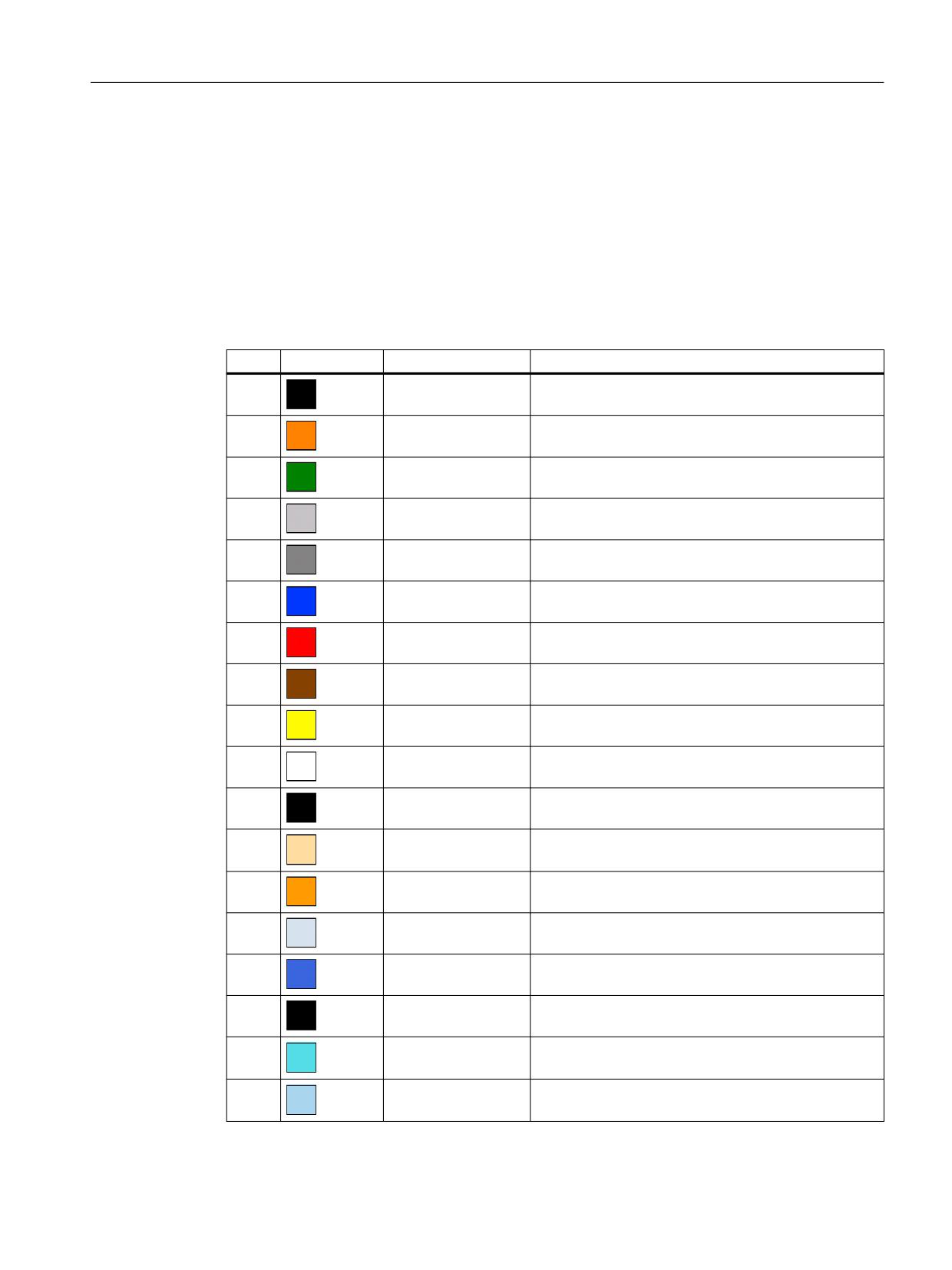
System colors
A uniform color table is available for configuring dialogs (subset of the respective standard
colors). The color of an element (text, input field, backg18round, etc.) can be selected from the
following options (between 0 and 133).
As an alternative to the predefined colors, you can also specify colors as RGB values
("#RRGGBB").
Index
Pictogram
Color
Color description
1
Black
2
Orange
3
Dark green
4
Light gray
5
Dark gray
6
Blue
7
Red
8
Brown
9
Yellow
10
White
126
Black
Font color of an input/output field that is currently in
focus
127
Light orange
Background color of an input/output field that is cur-
rently in focus
128
Orange
System color focus
129
Light gray
Background color
130
Blue
Header color (active)
131
Black
Header font color (active)
132
Turquoise
Background color of a toggle field
133
Light blue
Background color of a list box
SINUMERIK Integrate Run MyScreens
Programming Manual, 06/2019, A5E40869575B AC
311
Reference lists
A.5 List of language codes used in file names
A.5
List of language codes used in file names
Supported languages
Standard languages:
Language
Abbreviation in file name
Chinese simplified
chs
German
deu
English
eng
French
fra
Italian
ita
Spanish
esp
Other languages:
Language
Abbreviation in file name
Chinese traditional
cht
Danish
dan
Finnish
fin
Indonesian
ind
Japanese
jpn
Korean
kor
Malay
msl
Dutch
nld
Polish
plk
Portuguese (Brazil)
ptb
Romanian
rom
Russian
rus
Swedish
sve
Slovakian
sky
Slovenian
slv
Thai
tha
Czech
csy
Turkish
trk
Hungarian
hun
Vietnamese
vit
SINUMERIK Integrate Run MyScreens
312
Programming Manual, 06/2019, A5E40869575B AC
Reference lists
A.6 List of accessible system variables
A.6
List of accessible system variables
References
List Manual System Variables/PGAsl/
SINUMERIK Integrate Run MyScreens
Programming Manual, 06/2019, A5E40869575B AC
313
Reference lists
A.7 Behavior when opening the dialog (attribute CB)
A.7
Behavior when opening the dialog (attribute CB)
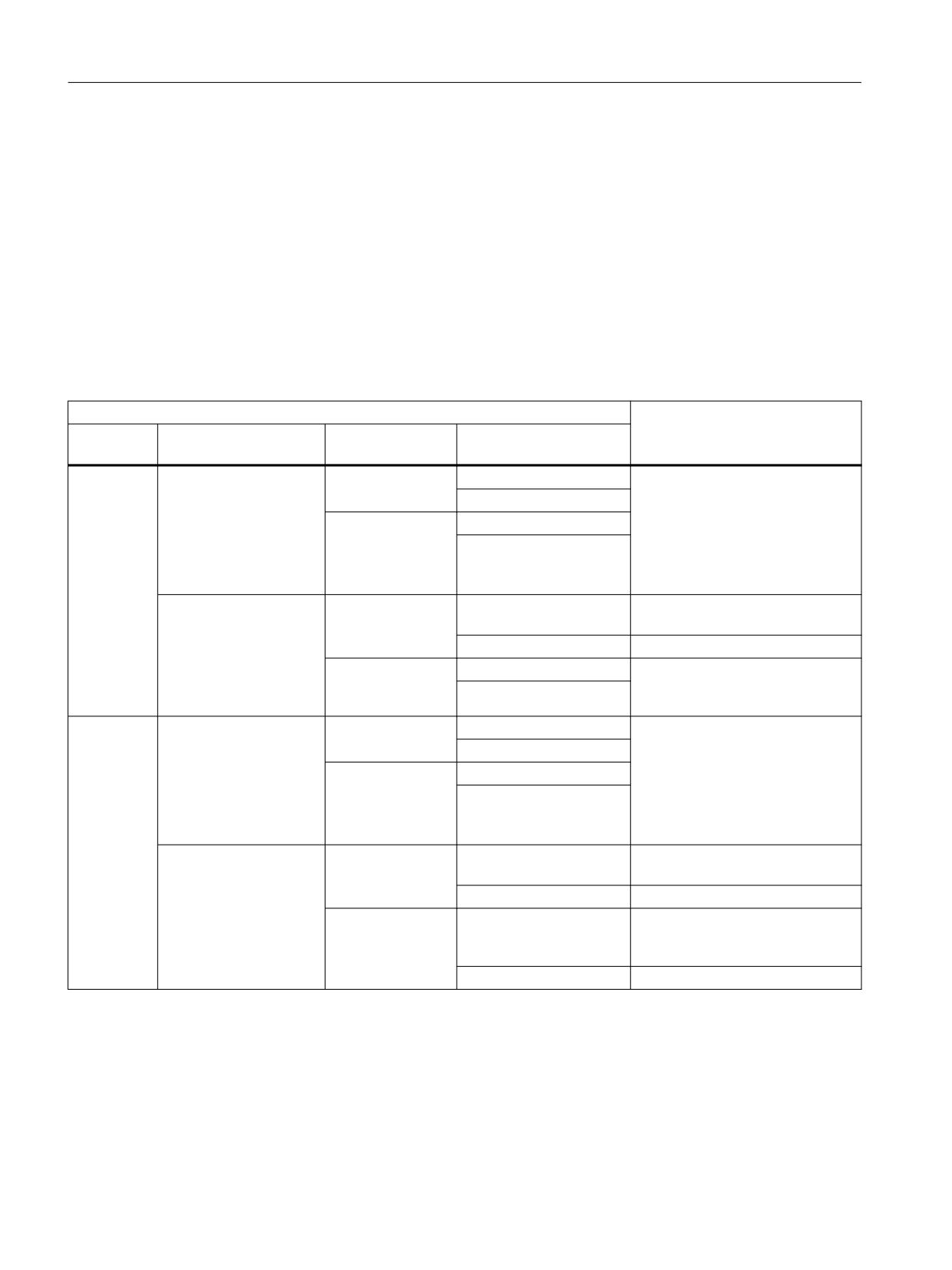
The following table provides an overview of the conditions when the CHANGE method is called.
The following applies to attribute CB:
CB0
The CHANGE method is triggered when the screen is displayed if the variable has a valid value
at this time (e.g. through default setting or NC/PLC variable).
CB1 (default)
The CHANGE method is not explicitly triggered when the screen is displayed. If the variable has
a configured NC/PLC variable, then the CHANGE method is of course still called.
Condition
Response
Type
System or user variable
Default setting
Execute the CHANGE
method
I/O field
Yes
Yes
Yes
Due to the configured NC/PLC var-
iable, there is always at least one
No
automatic call of the CHANGE
No
Yes
method with the current value of
No
the NC/PLC variable. The pre-as-
signment of CB does not have an
effect.
No
Yes
Yes
The CHANGE method is called
with the pre-assigned value.
No
The CHANGE method is not called.
No
Yes
No call because there is no valid
value present to call the CHANGE
No
method.
Toggle
Yes
Yes
Yes
Due to the configured NC/PLC var-
iable, there is always at least one
No
automatic call of the CHANGE
No
Yes
method with the current value of
No
the NC/PLC variable. The pre-as-
signment of CB does not have an
effect.
No
Yes
Yes
The CHANGE method is called
with the pre-assigned value.
No
The CHANGE method is not called.
No
Yes
The CHANGE method is called
with the first pre-assigned value of
(per default the
the toggle list.
first value from the
toggle is assigned)
No
The CHANGE method is not called.
See also
CHANGE (Page 127)
SINUMERIK Integrate Run MyScreens
314
Programming Manual, 06/2019, A5E40869575B AC
Tips and tricks
B
B.1
General tips
●
If possible, use the OPI version for system variables ($ variables).
Reason:
Avoids complex name resolution.
Example:
Instead of "$R[10]", it is better to use "/Channel/Parameter/R[u1,10]".
●
Avoids cyclic (similar) setting, e.g. of the screen and variable HLP property. Compare the
value to be set with the current value first, and only set it when it is different.
Reason:
Avoid a time-consuming search of the resolution-dependent help screens.
Example:
DEF MyVar=(R3///,"X1",,"mm"/WR1//"$AA_IM[0]")
CHANGE(MyVar)
IF MyVar.VAL < 100
HLP="mypic1.png"
ELSE
HLP="mypic2.png"
ENDIF
END_CHANGE
Recommendation:
CHANGE(MyVar)
IF MyVar.VAL < 100
IF HLP <> "mypic1.png"
HLP="mypic1.png"
ENDIF
ELSE
IF HLP <> "smypic2.png"
HLP="mypic2.png"
ENDIF
ENDIF
END_CHANGE
SINUMERIK Integrate Run MyScreens
Programming Manual, 06/2019, A5E40869575B AC
315
Tips and tricks
B.1 General tips
● Replace several RNP() functions in succession with one MRNP() function.
Replace several RDOP() functions in succession with one MRDOP() function.
Reason:
Reduces the communication load and increases the performance.
● Do not read drive parameters faster than in a 1 second cycle, slower is better.
Reason: The communication with the drives can otherwise be extremely disturbed or even
cause failures.
● Avoid successive arithmetic operations with system or user variable-connected dialog
variables. Use, for example, register (REG[x]) or (invisible) help variables for this.
Reason: Each assignment of a value results in a write operation in the connected system or
user variable.
● Similar code used in different blocks should be combined in a SUB block for reasons of
transparency, serviceability and performance (when displaying the screen). It can then be
called at the appropriate positions with the CALL() function.
● By monitoring the CPU load in the dialog line (setting in slguiconfig.xml), it is possible to
investigate the effects of changes in the screen on the performance.
SINUMERIK Integrate Run MyScreens
316
Programming Manual, 06/2019, A5E40869575B AC
Tips and tricks
B.2 Tips for debugging
B.2
Tips for debugging
● Use the DEBUG() function for diagnostic purposes. When the DEBUG() function is called,
the transferred string is written to the "easyscreen_log.txt" file. The output of information in
the dialog line by the DLGL() function can also be helpful.
However, after completion of the screen development, this function should be removed
again for performance reasons or commented out.
● The "easyscreen_log.txt" file should have no entries after the development of a screen is
completed.
SINUMERIK Integrate Run MyScreens
Programming Manual, 06/2019, A5E40869575B AC
317
Tips and tricks
B.3 Tips for the CHANGE method
B.3
Tips for the CHANGE method
●
Always keep CHANGE methods very short and small, particularly for those whose variables
are connected to a system or user variable and change very frequently.
Reason:
Increases the screen performance.
●
If possible, do not configure any RNP() functions in CHANGE methods. Instead, it is better
to configure an invisible variable parallel to the system or user variable to be read and then
use this.
Reason:
An RNP() function would be issued with each call. Otherwise, the current value which is
already available would be simply accessed.
Example:
A name resolution is performed via RNP() for each change of the axis motion in order to read
channel-specific machine data:
DEF AXIS_POSITION_X = (R///,""///"$AA_IM[X]")
CHANGE(AXIS_POSITION_X)
DLGL("Axis """ << RNP("$MC_AXCONF_GEOAX_NAME_TAB[0]") << """
has moved: "
<< AXIS_POSITION_X)
END_CHANGE
Keep the channel-specific machine data up-to-date with the aid of an invisible variable, copy
each value change to a temporary variable, e.g. register.
This temporary variable can then be used in the CHANGE method of the value change for
the axis position without making a name resolution of the machine data each time and the
subsequent read access:
DEF AXIS_POSITION_X = (R///,""///"$AA_IM[X]")
DEF AXIS_NAME_X = (S///,""/WR0//"$MC_AXCONF_GEOAX_NAME_TAB[0]")
CHANGE(AXIS_NAME_X)
REG[0] = AXIS_NAME_X
END_CHANGE
CHANGE(AXIS_POSITION_X1)
DLGL("Axis """ << REG[0] << """ has moved " << AXIS_POSITION_X)
END_CHANGE
SINUMERIK Integrate Run MyScreens
318
Programming Manual, 06/2019, A5E40869575B AC
Tips and tricks
B.3 Tips for the CHANGE method
● The update rate and therefore the execution of the associated CHANGE method of
variables that are connected to system or user variables with very frequent value changes,
can be reduced by using the UR variable property, e.g. variable that is coupled to the actual
axis values.
Reason:
In this way, the associated CHANGE method is executed in a fixed specified grid for a value
change.
SINUMERIK Integrate Run MyScreens
Programming Manual, 06/2019, A5E40869575B AC
319
Tips and tricks
B.4 Tips for DO LOOP loops
B.4
Tips for DO LOOP loops
As loops can impair the performance of SINUMERIK Operate, depending on the configuration,
they should be used carefully and if possible without time-intensive actions.
A register (REG[]) should also be used as run variable, because normal display variables
(particularly those with OPI connection) also impair the system performance due to the frequent
updates or write operations.
Note that the number of script lines executed "in one operation", is currently limited to 10,000.
When this number is reached, the script execution is aborted with an appropriate entry in the
"easyscreen_log.txt" file.
Reason:
● Prevention of endless loops
● "Run MyScreens" must remain operable
SINUMERIK Integrate Run MyScreens
320
Programming Manual, 06/2019, A5E40869575B AC
Animated elements
C
C.1
Introduction
Introduction
The manual describes working with the X3D Viewer with which you can integrate animated and
non-animated graphical scenes (animated elements) - called help screens in the following -
into the graphical user interface of SINUMERIK Operate as of Version V4.7 SP1 .
You can show motion sequences and parameters in context-sensitive help screens. This helps
you to improve the operation of applications and make the user interface more appealing.
Implementation of your initial idea to the final help screen is described in the steps below:
● Creation of graphical elements and 3D models for the help screens that will eventually
appear in the X3D Viewer (see Chapter Modeling (Page 323)).
● Creation of the scene description file in which the model data of the graphics file will be
assigned to the scenes and animations to be displayed at particular points (see
Chapter Structure of the scene description file (Page 329)).
● Conversion of the X3D files and XML files into HMI files (see Chapter Conversion to hmi file
(Page 334)).
● C++ integration of the X3D Viewer into your own application (see Chapter Implementation
example (Page 337)).
● Application in Run MyScreens (see Chapter Display in Run MyScreens (Page 338)).
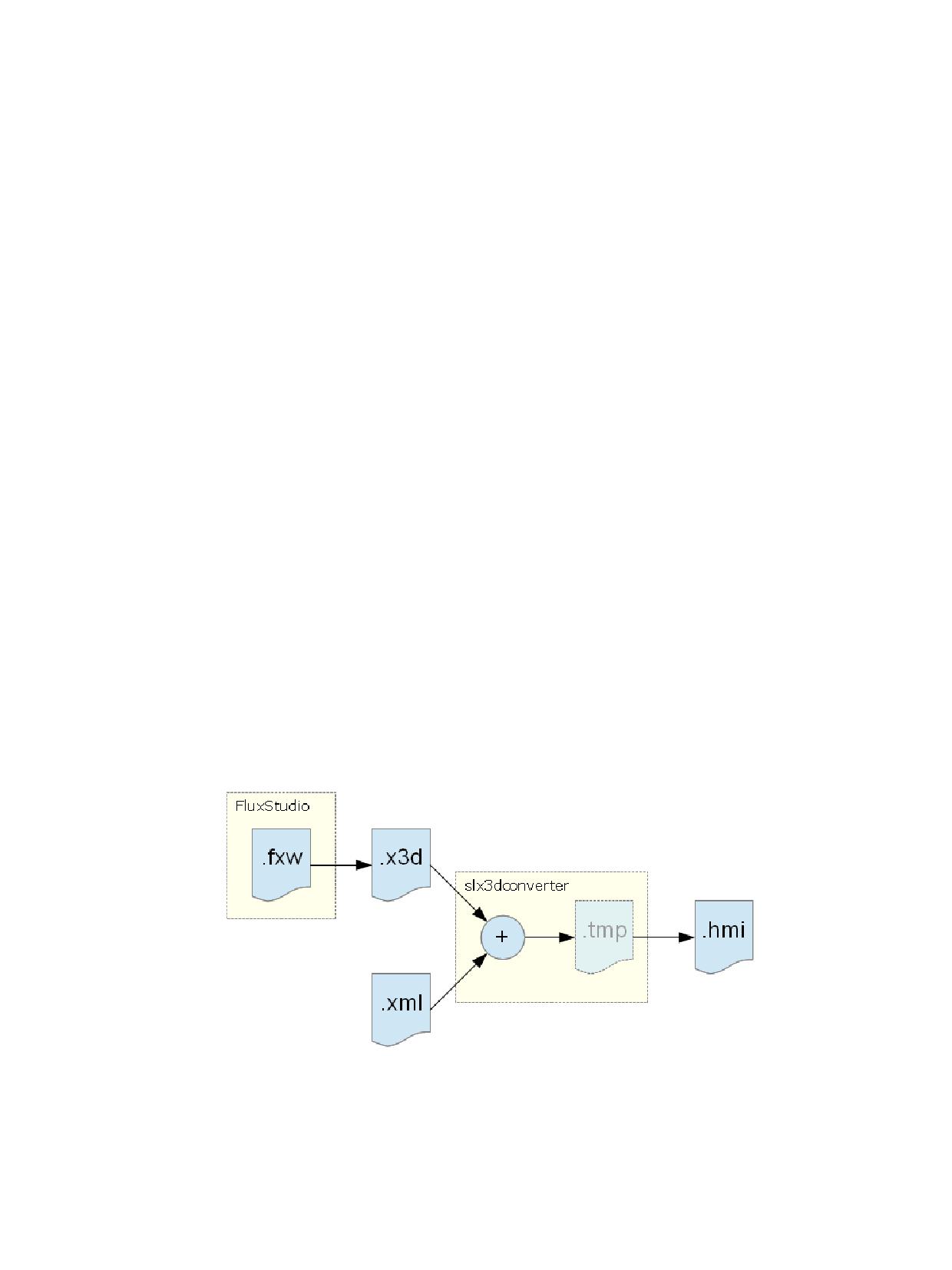
Overview of the file formats
Figure C-1
File formats
SINUMERIK Integrate Run MyScreens
Programming Manual, 06/2019, A5E40869575B AC
321
Animated elements
C.1 Introduction
File format
Description
.fxw
Flux Studio (3D) graphics file
.x3d
Model file in exchange format
.xml
Definition file for animations and scenes
.hmi
Output file for the X3D Viewer
SINUMERIK Integrate Run MyScreens
322
Programming Manual, 06/2019, A5E40869575B AC
Animated elements
C.2 Modeling
C.2
Modeling
C.2.1
Requirements
The aim of the modeling is to create a file with the generated 3D models in .x3d file format, an
official standard for 3D contents.
Modeling is performed in the Flux Studio Web3D authoring tool . The Flux Studio Web3D
authoring tool is a freely available 3D modeling tool with versatile export and import options.
Requirements
● You have installed the Flux Studio Web3D authoring tool, Version 2.1.
● You are familiar with modeling and use of Flux Studio.
● File format .x3d is not described in any detail in this document, adequate knowledge of the
subject is assumed.
Note
You can download the Flux Studio Web3D authoring tool from the Internet via the following link:
mediamachines.wordpress.com/flux-player-and-flux-studio)
C.2.2
Rules for modeling
Observe the following rules when modeling. You will only be able to process your help screen
file if you have followed these rules correctly.
Rules for modeling
1. The time sensor must have the name "Animation".
2. All related elements must be assigned to a group.
3. All groups must be set to the following position:
x = 0, y = 0, z = 0
4. To make the groups invisible, the translation values are set as follows:
x = 1000000, y = 1000000 and z = 1000000
5. The following elements must have the same name both in the Flux Studio graphic models
and in the XML scene definitions (cf. Chapter Overview (Page 329)):
- Tool
- Cameras
SINUMERIK Integrate Run MyScreens
Programming Manual, 06/2019, A5E40869575B AC
323
Animated elements
C.2 Modeling
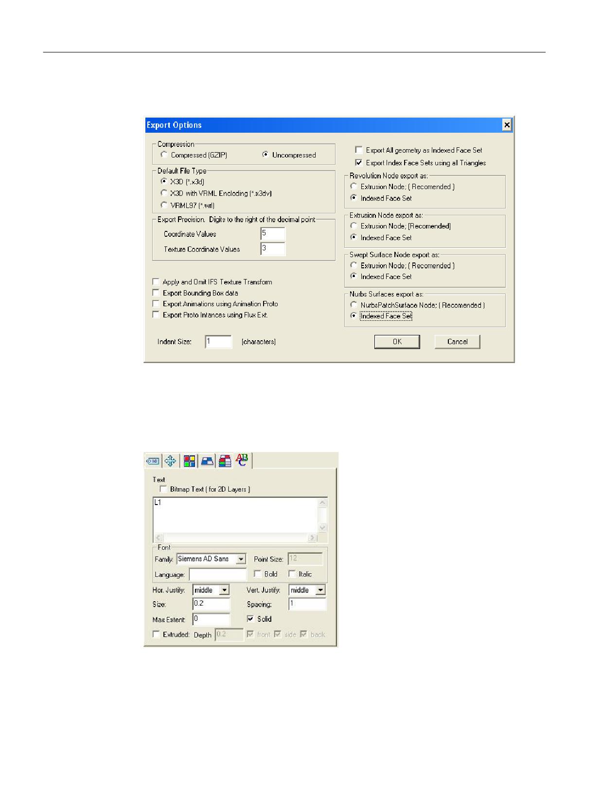
6. Before you can create a .x3d file you must make the following settings in dialog box "Export
Options":
Figure C-2
Settings in the Export Options dialog box
7. We recommend the following settings for texts (see also the following dialog box):
- Texts must always be centered.
- The size of the text should be 0.2. This size allows you to position the text easily. The text
output by the X3D Viewer is in the font size of the user interface, irrespective of this value.
Figure C-3
Settings for text
SINUMERIK Integrate Run MyScreens
324
Programming Manual, 06/2019, A5E40869575B AC
Animated elements
C.2 Modeling
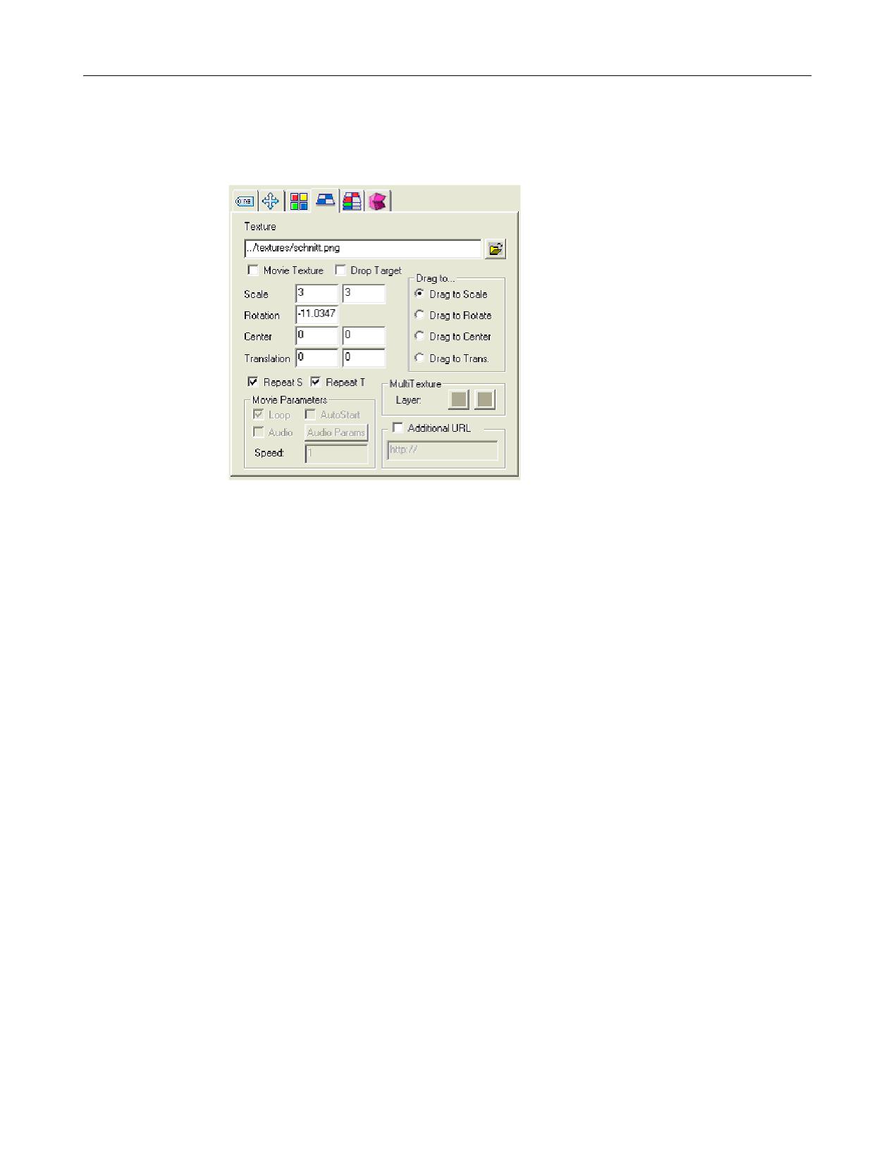
8. To create hatching, use file schnitt.png as the texture. The lines always go from the bottom
left to the top right at an angle of 45°. You should set the scaling to 3 in both dimensions. The
rotation depends on the construction type and must be adapted manually.
Figure C-4
Settings for hatching
9. We recommend the following sizes/dimensions for the blanks:
- Cylinder for turning operation:
Length = 5.5 ; Radius = 1.4 (cf. template turning_blank.fxw)
- Cube for milling operation
x = 4.75 ; y = 3 ; z = 3 (cf. template milling_blank.fxw)
See also
XML commands (Page 329)
C.2.3
Importing graphics (models)
In Flux Studio, you can import external graphics (models). You can store frequently used
models, such as tools, as .x3d or .hmi files centrally for further use as finished elements in other
help screens. You will find a list of supplied modeling templates in Chapter Modeling templates
(Page 327).
Complex objects can also be created with other modeling tools, such as Cinema4D, and then
imported.
A description of how you can reuse these models is given below.
Import as inline
Flux Studio uses the object "Inline" for importing .x3d files. It allows you to link in external
elements without multiplying the 3D data of these models.
SINUMERIK Integrate Run MyScreens
Programming Manual, 06/2019, A5E40869575B AC
325
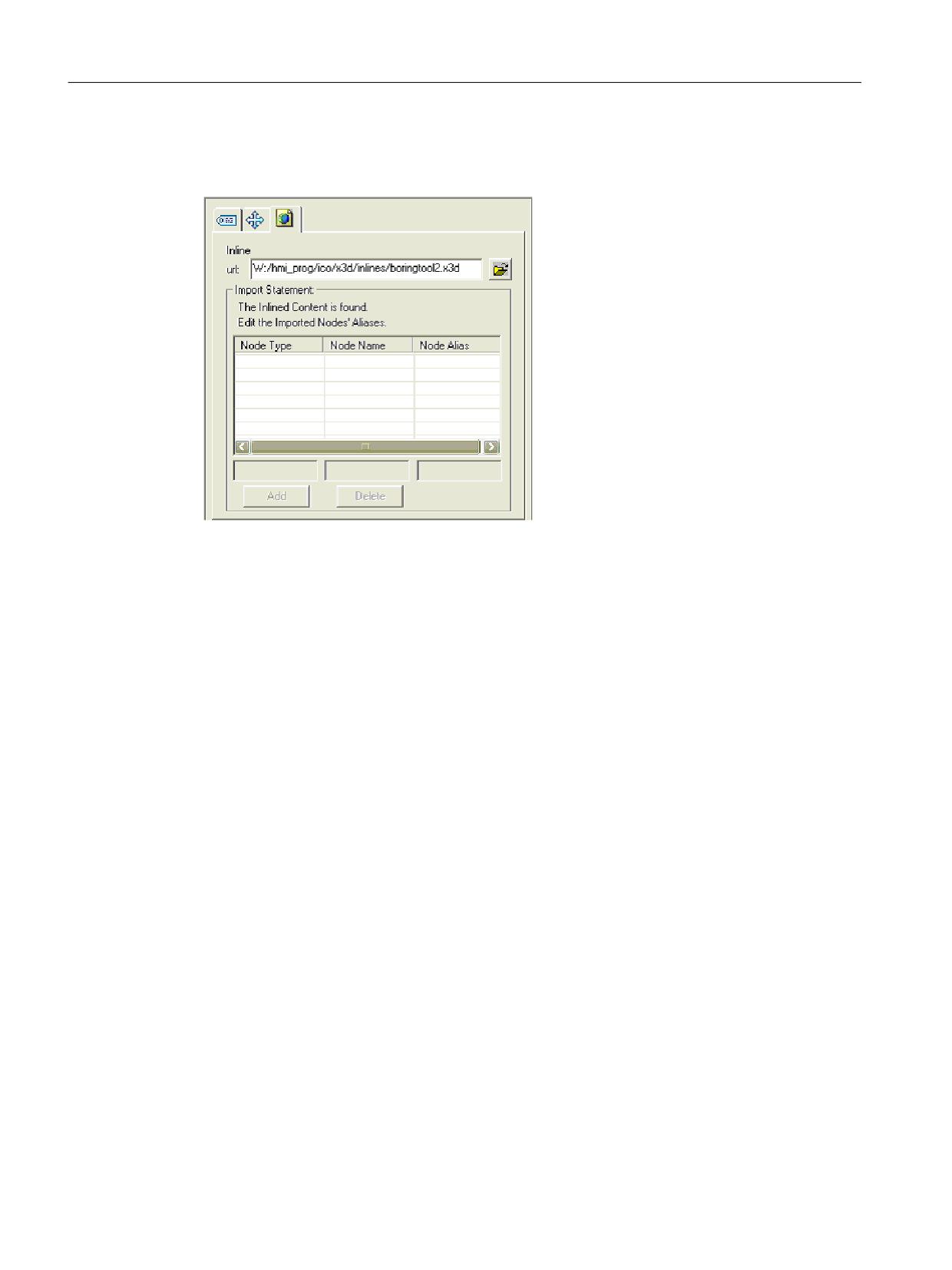
Animated elements
C.2 Modeling
Insert the object with menu item Create -> Create Inline. Then enter a file name in the object
properties.
Figure C-5
Importing with object "Inline"
SINUMERIK Integrate Run MyScreens
326
Programming Manual, 06/2019, A5E40869575B AC
Animated elements
C.2 Modeling
Importing 3D model data
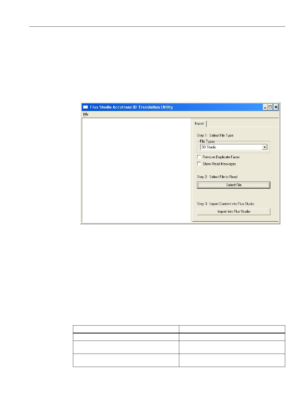
Proceed as follows to import model data from a file.
1. Open dialog box "Flux Studio Accutrans3D Translation Utility" via menu item File -> Import
Other Format .
2. Select a format from the "File Types" list box. For example, to import a Cinema4D file, select
file type "3D Studio."
3. Then select a file with Select Files and start import.
Figure C-6
Importing 3D model data
The model data from the Cinema4D file is inserted as a complete group. All cameras and any
other information that is additionally imported should be deleted. Only the graphics elements of
the Cinema4D file are required.
C.2.4
Modeling templates
In this chapter, you will find a list of graphics elements on which you can base your design,
colors, and sizes. To maintain a uniform "look and feel" in the user interface, we recommend
using the style of the templates or the templates themselves for creating your own graphics.
General
Template
Description
intersection_texture.png
Texture for an sectioned area
rapid_traverse_line_hori.fxw
Horizontal line to illustrate the tool traversing path
during rapid traverse
rapid_traverse_line_vert.fxw
Vertical line to illustrate the tool traversing path
during rapid traverse
SINUMERIK Integrate Run MyScreens
Programming Manual, 06/2019, A5E40869575B AC
327

Animated elements
C.2 Modeling
Template
Description
feed_traverse_line_hori.fxw
Horizontal line to illustrate the tool path during feed
feed_traverse_line_vert.fxw
Vertical line to illustrate the tool path during feed
dimensioning_lines_hori.fxw
Horizontal projection lines
dimensioning_lines_vert.fxw
Vertical projection lines
z1_inc.fxw
Horizontal dimension line with the identifier Z1
x1_inc.fxw
Vertical dimension line with the identifier X1
3d_coordinate_origin.fxw
3D coordinate origin
3d_zero_point.fxw
3D zero point
Turning
Template
Description
turning_blank.fxw
The blank for turning technology: A simple cylinder
turning_centerline.fxw
Center line
turning_centerpoint.fxw
Coordinate origin to display the zero point in the
WCS
turning_refpoint.fxw
Reference point, for example, for a machining op-
eration
turning_machining_area.fxw
Boundary lines for the machining area
Milling
Template
Description
milling_blank.fxw
The blank for milling technology: A simple cube
milling_centerline.fxw
Center line
milling_refpoint.fxw
Reference point, for example, for a machining op-
eration
SINUMERIK Integrate Run MyScreens
328
Programming Manual, 06/2019, A5E40869575B AC
Animated elements
C.3 XML commands
C.3
XML commands
C.3.1
Overview
The scene description file (*.xml) is required so that the X3D Viewer can access the graphics.
In the scene description file, you assign the scene names that are called from the configuration
to the times in the *.x3d file (time sensor) at which the graphics are positioned.
C.3.2
Structure of the scene description file
The structure of the scene description file is shown below together with an explanation of the
relevant XML commands:
Design and description
<!-- Treatment of the plane-dependent texts for turning -->
<TextPlane plane="G18_ZXY" />
Description
<TextPlane plane="G18_ZXY" />
Treatment of the plane-dependent texts (axis
names) specifically for turning. If, for example,
a text with the identifier "Z" is used (for G18
first geometry axis), the corresponding geom-
etry axis identifier of the control will be shown
in the help screen (for example, "Z").
<!--Text alignment -->
<TextPosition center='true' />
Description
<TextPosition center='true' />
Marking that the texts are centered. This is rel-
evant to the display of the texts in rotated
screens. We recommend using this setting.
<!--Adapting the tool speed -->
<ToolSpeedFactors planeSpeedFactor="0.4" rapidSpeedFactor="0.7"
reducedSpeedFac¬tor="1.0"/>
SINUMERIK Integrate Run MyScreens
Programming Manual, 06/2019, A5E40869575B AC
329
Animated elements
C.3 XML commands
Description
<ToolSpeedFactors
This entry can be added if the tool speeds are
to be modified.
planeSpeedFactor="0.4"
Factor for the feedrate ( 0.4 = 40% )
rapidSpeedFactor="0.7"
Factor for rapid traverse ( 0.7 = 70% )
reducedSpeedFactor="0.1" />
Factor for a third speed ( 0.1 = 10% )
<!--Definition of an animation-->
<SceneKey name='BoringAnimation' masterRotationSpeed="-64.0"
maxRotAngle="45.0" begin-Time='0.110 endTime='0.118 view='camiso'
speedMaster='boringtool' Type="VIEW_3D_TURN_CYL">
Description
<SceneKey name='BoringAnimation'
Name of the animation
masterRotationSpeed="-64.0"
Direction of rotation and rotation speed of the
tool.
The setting is optional.
maxRotAngle="45.0"
To avoid aliasing effects (tool seems to be
turning in the wrong direction). The value is
usually a fourth of the symmetry of the tool.
The setting is optional.
beginTime='0.110
Start time of the animation on the time sensor
endTime='0.118'
End time of the animation on the time sensor
view='camiso'
Camera to be used for the animation
speedMaster='boringtool'
Name of the tool for the animation
type="VIEW_3D_TURN_CYL">
View type defines the view (see Section View
type (Page 333))
<!-- Elements -->
<Element name='1' time='0.110' feed='rapid' dwell=’2’/>
<Element name='2' time='0.112' feed='rapid'/>
<Element name='3' time='0.114' feed='rapid'/>
<Element name='4' time='0.116' feed='plane'/>
<Element name='5' time='0.118' feed='plane'/>
Description
<Element name='1'
Specifies that it is the first element of the ani-
mation.
time='0.110'
Time of the first element on the time sensor
SINUMERIK Integrate Run MyScreens
330
Programming Manual, 06/2019, A5E40869575B AC
Animated elements
C.3 XML commands
feed='rapid'
Traversing speed of the element
plane = machining feedrate
rapid = rapid traverse
reduced = reduced speed, slower than "plane"
dwell=’2’/>
Pause in the traversing motion of the anima-
tion. A rotating tool continues to rotate.
<!-- End of animation definition -->
</SceneKey>
Description
</SceneKey>
End of the animation definition
<!-- Existing animation as source for a new animation -->
<SceneKey source=''BoringAnimation' name=''BoringAnimationRear' mirror='
MirrorScreenX ' />
Description
<SceneKey source=''BoringAnimation'
Name of an animation that is to use another
animation as its source.
name=''BoringAnimationRear'
Name of the new animation based on the
source
mirror=' MirrorScreenX ' />
Mirroring in the direction of the X axis, output is
in the new animation.
<!-- Definition of a static scene (screen), (four examples) -->
<SceneKey name='Default' time='0.026' view='camiso'
type="VIEW_3D_DRILL_CUT"/>
<SceneKey name='Cut' time='0.046' view='camside' type="VIEW_SIDE"/>
<SceneKey name='Z1ink' time='0.056' view='camside' type="VIEW_SIDE"
highLightedGroup='dad_Z1ink'/>
<SceneKey name='Z1abs' time='0.066' view='camside' type="VIEW_SIDE"
highLightedGroup='dad_Z1abs'/>
Description
<SceneKeyname=’Z1abs'
Screen name
time='0.066'
Time of the screen on the time sensor
view='camside'
Camera to be used for the screen
SINUMERIK Integrate Run MyScreens
Programming Manual, 06/2019, A5E40869575B AC
331
Animated elements
C.3 XML commands
type="VIEW_SIDE"
View type defines the view (see Section View
type (Page 333))
highLightedGroup='dad_Z1abs'/>
Name of the group to be highlighted. The
group has been called "Z1abs" in Flux Studio.
The prefix "dad_" is automatically added by
Flux.
<!-- End of xml file -!>
C.3.3
Mirroring and rotations
Mirroring or rotation of the image or model is defined with the mirror command.
Description
mirror="RotateScreenX"
The screen is rotated around the X axis
mirror="RotateScreenY"
The screen is rotated around the Y axis
mirror="RotateScreenZ"
The screen is rotated around the Z axis
mirror="MirrorScreenX”
The screen is mirrored along the X axis
mirror="MirrorScreenY"
The screen is mirrored along the Y axis
mirror="MirrorScreenZ"
The screen is mirrored along the Z axis
mirror="RotatePieceX”
The model is rotated around the X axis
mirror="RotatePieceY"
The model is rotated around the Y axis
mirror="RotatePieceZ"
The model is rotated around the Z axis
mirror="MirrorPieceX"
The model is mirrored along the X axis
mirror="MirrorPieceY"
The model is mirrored along the Y axis
mirror="MirrorPieceZ"
The model is mirrored along the Z axis
All rotate and mirror options can be combined. A rotation angle must be defined for rotation.
Examples
mirror="RotatePieceZ=180"
mirror="RotatePieceZ=-90 MirrorScreenX"
mirror="RotateScreenY=90"
mirror="MirrorPieceX MirrorPieceY"
mirror="MirrorPieceZ RotatePieceX=-90"
SINUMERIK Integrate Run MyScreens
332
Programming Manual, 06/2019, A5E40869575B AC
Animated elements
C.3 XML commands
C.3.4
View type
You define the views with the view type. The views are based on empirical values and rules that
produce a sensible representation of the objects.
This ensures that the representation of the objects matches the coordinate system settings
made in the user interface (MD 52000 $MCS_DISP_COORDINATE_SYSTEM or MD 52001
$MCS_DISP_COORDINATE_SYSTEM_2).
Description
"VIEW_STATIC"
Direct view without conversion
"VIEW_3D_TURN_CYL"
3D view for turning operations (cylinder)
"VIEW_3D_MILL_CUBE"
3D view for milling operations (cube)
"VIEW_3D_DRILL_CUT"
3D view for drilling operations (sectional view)
"VIEW_SIDE"
2D view for drilling operations (sectional view)
"VIEW_TOP_GEO_AX_1"
2D view from the direction of the 1st geometry
axis
"VIEW_TOP_GEO_AX_2"
2D view from the direction of the 2nd geometry
axis
"VIEW_TOP_GEO_AX_3"
2D view from the direction of the 3rd geometry
axis
SINUMERIK Integrate Run MyScreens
Programming Manual, 06/2019, A5E40869575B AC
333
Animated elements
C.4 Conversion to hmi file
C.4
Conversion to hmi file
Note
The X3D files and their associated XML files are converted to HMI files when the HMI is
powered up.
For each X3D file, a corresponding XML file of the same name must be created. To do this, you
store the X3D files and XML files in directory search path of HMI\ico\x3d\turning
or milling. You proceed in the same way with the .ts files.
SINUMERIK Integrate Run MyScreens
334
Programming Manual, 06/2019, A5E40869575B AC
Animated elements
C.5 Display in Create MyHMI /3GL
C.5
Display in Create MyHMI /3GL
C.5.1
X3D Viewer
If you want to display particular help screens in a separate OA application you must integrate
the X3D Viewer widget into its own OA application.
The X3D Viewer widget provides interfaces, which enable X3D contents to be presented in the
HMI.
Class SlX3dViewerWidget is provided for displaying graphical scenes. The definition of the
class can be found in the corresponding slx3dviewerwidget.h header file in the global GUI
include directory \hmi_prog\gui\include.
C.5.2
Class SlX3dViewerWidget
The class provides a flexible widget that autonomously displays the contents of a model file
specified during runtime and, if required, runs the animation.
The interface of the class comprises the Constructor, Destructor, and two methods for
controlling the graphical output.
As a direct derivative of the Qt class QWidget, a much more expansive interface is available,
which will not be described in any further detail here, (for example, show(), hide() and
resize(...). For more information, please refer to the Qt documentation).
C.5.3
Public methods
SlX3dViewerWidget ( QWidget* pParent = 0 )
Constructor of the X3D Viewer widget.
Parameters
Meaning
pParent
The parameter is passed on to the constructor of
the Qwidget.
~SlX3dViewerWidget ( )
Destructor of the X3D Viewer widget.
Parameters
Meaning
-
-
SINUMERIK Integrate Run MyScreens
Programming Manual, 06/2019, A5E40869575B AC
335

Animated elements
C.5 Display in Create MyHMI /3GL
C.5.4
Public slots
void viewSceneSlot ( const QString& rsFileName, const QString& rsScene, const QString&
rsAnimationScene, int nChannel, int nPlane, SlStepTechnology nTechnology )
With the viewSceneSlot method, the X3D Viewer is instructed to load the rsScene static scene
and the rsAnimationSzene animated scene from the rsFileName file and display them
alternately.
The static scene and then the animated scene are repeatedly alternately displayed for a fixed
time.
If no static scene is specified, the animation will be shown immediately; an animated scene may
also not have been specified.
Channel number, plane and technology are used to rotate the scenes to the correct position
(depending on the set machine coordinate system).
Parameters
Meaning
rsFileName
Name of the file that contains the scenes to be
displayed
rsScene
Name of the static scene.
rsAnimationScene
Name of the animated scene.
nChannel
Channel number
nPlane
Plane
nTechnology
Technology
The following constants are defined for the SlStep-
Technology enumeration type:
● SL_STEP_NO_TECHNOLOGY
● SL_STEP_MILLING
● SL_STEP_TURNING
● SL_STEP_SURFACE_GRINDING
● SL_STEP_CIRCULAR_GRINDING
void viewSceneSlot ( const QString& rsFileName, const QString& rsScene, const QString&
rsAnimationScene )
A simplified form of the viewSceneSlot method with which the X3D Viewer can be instructed to
load and display the rsScene static scene and/or the rsAnimationSzene animated scene from
the rsFileName file.
Parameters
Meaning
rsFileName
Name of the file that contains the scenes to be
displayed.
rsScene
Name of the static scene.
rsAnimationScene
Name of the animated scene.
SINUMERIK Integrate Run MyScreens
336
Programming Manual, 06/2019, A5E40869575B AC
Animated elements
C.5 Display in Create MyHMI /3GL
C.5.5
Libraries
In order to be able to apply the X3D Viewer in your own projects, the list of library dependencies
must be extended by the 'slx3dviewer.lib' entry.
C.5.6
Implementation example
You will find an implementation example in the package Create MyHMI/3GL under \examples
\GUIFrameWork\SlExGuiX3D.
C.5.7
Machine data
Display MD 9104 $MM_ANIMATION_TIME_DELAY
Time delay in seconds until the animation is started for help screens. The setting does not apply
to help screens that are only animated.
The setting applies globally to all animations of SINUMERIK Operate.
C.5.8
Notes about use
● The animation is interrupted if the X3D Viewer widget is hidden. If this happens, there is no
need to choose a scene selection without animation.
● You should avoid frequent or multiple instantiation of the X3D Viewer widget as this reduces
performance and memory capacity. The use (implementation) of an X3D Viewer Singleton
is recommended in such application scenarios.
● The X3D Viewer can also be used in signal slot concepts.
● If an error occurs (for example, a file not found or unknown scene name), the X3D Viewer
widget opens a message area. This area is automatically hidden again when another help
screen is activated.
SINUMERIK Integrate Run MyScreens
Programming Manual, 06/2019, A5E40869575B AC
337
Animated elements
C.6 Display in Run MyScreens
C.6
Display in Run MyScreens
This section is intended for experienced "Run MyScreens" developers. Necessary backg18round
knowledge is provided in the associated documentation.
In addition to using screens in .bmp or .png format, animated help screens can also be
displayed with the X3D Viewer.
To integrate help screens, use the Run MyScreens interface in the usual way.
To output images in .bmp or .png format, XG0 is entered in the definition of a dialog box in the
Attributes section or the parameter is left empty. To integrate X3D help screens in a dialog, you
must enter XG1 in the attributes.
//M(MASK_F_DR_O1_MAIN/$85407////52,80/XG1)
The following parameters are required to activate the individual help screens; their meaning is
described in Section 5.3 Public slots:
1. File name
2. StaticScene (optional)
3. AnimationScene (optional)
4. Technology (optional)
5. Plane (optional)
The parameters are combined into a character string in this order, separated by a comma.
Hlp = "File name,StaticScene,AnimationScene,Technology,Plane"
Examples
● The default help screen can be set with the specified variable Hlp.
In the following example, the "MyAnimation" animation is output from the "MyDlgHelp.hmi"
file. No StaticScene is specified, i.e. no static scene is output. No specifications are made
for the Technology and Plane, i. e. default values are used.
Hlp = "MyDlgHelp.hmi,,MyAnimation"
● The hlp property can be set on a specific help screen for the individual parameters of the
input screen.
In the following example, the static "MyParam" scene and the "MyAnimation" animation are
output from the "MyDlgHelp.hmi" file in the G17 plane. No specification is made for the
Technology, i.e. a default value is used.
VarMyParam.hlp = "MyDlgHelp.hmi,MyParam,MyAnimation,,G17"
SINUMERIK Integrate Run MyScreens
338
Programming Manual, 06/2019, A5E40869575B AC
Glossary
Access level
Graduated system of authorization, which makes the accessibility and utilization of functions on
the operator interface dependent on the authorization rights of the user.
Array
An array can be used to organize data of a standard data type stored in the memory in such a
way that it is possible to access the data via an index.
Attribute
Characteristic that assigns specific → Properties to an object (→ Dialog or → Variable).
Column index
Column number of an array
Configuration file
File, which contains definitions and instructions that determine the appearance of → Dialogs
and their → Functions.
Definition lines
Program section in which → Variables and softkeys are defined
Dialog
Display of the → User interface
● Dialog-dependent softkey menu
Softkey menu, which is called from a newly configured dialog.
● Dialog-independent softkeys
Softkeys, which are not called from a dialog, i.e., start softkey and softkey menus, which the
user configures before the first, new dialog.
Editor
ASCII Editor with which characters can be entered in a file and edited.
SINUMERIK Integrate Run MyScreens
Programming Manual, 06/2019, A5E40869575B AC
339
Glossary
Event
Any action, which initiates execution of a → Method: Input of characters, actuation of softkeys,
etc.
Group
Reload unit for → Configuration file
Help variable
Internal arithmetic variable to which no → Properties can be assigned and is not, therefore,
visible in the → Dialog.
Hotkeys
6 keys on OP 010, OP 010C and SINUMERIK keyboards with hotkey blocks. Pressing the keys
selects an operating area directly. As an option, 2 additional keys can be configured as hotkeys.
Input/output field
Also I/O field: for inputting or outputting variable values.
Interpreter
The interpreter automatically converts the defined code from the → Configuration file into a
→ Dialog and controls its use.
Line index
Row number of an array
Menu tree
A group of interlinked → Dialogs
Method
Programmed sequence of operations executed when a corresponding → Event occurs.
Parameter
Parameters are variable elements of the programming syntax and are replaced by other words/
symbols in the → Configuration file.
SINUMERIK Integrate Run MyScreens
340
Programming Manual, 06/2019, A5E40869575B AC
Glossary
PI service
Function which, on an NC, executes a clearly defined operation. PI services can be called from
the PLC and the HMI system.
PLC hard key
PLC hard keys are provided via the PLC interface of the HMI software, just like hotkeys. The
functions, which can be triggered via the user interface, can be configured.
They take the form of MCP keys or evaluations of PLC signal logic operations in the PLC user
program. For this reason, they are referred to as "virtual keys".
Programming support
Provision of → Dialogs to assist programmers in writing → Parts programs with "higher-level"
components
Properties
Characteristics of an object (e.g of a → Variable)
Recompile
NC code sections can be generated in a → Part program from input fields in → Dialogs in the
→ Programming support system. Recompilation is the reverse operation. The input fields used
to generate a selected section of NC code are retrieved from the NC code and displayed in the
original dialog.
Selecting
A program formulated in the NC language, which specifies motion sequences for axes and
various special actions.
Simulation
Simulation of a → Parts program run without movement of the actual machine axes.
Softkey labels
Text/image on the screen, which is assigned to a softkey.
Softkey menu
All horizontal or all vertical softkeys
Start softkey
Softkey with which the first newly created → Dialog is started.
SINUMERIK Integrate Run MyScreens
Programming Manual, 06/2019, A5E40869575B AC
341
Glossary
Toggle field
A list of values in the → Input/output field; check with toggle field: The value input in a field must
be the same as one of the listed values.
User variable
Variables defined by the user in the → Parts program or data block.
Variable
Designation of a memory location, which can be displayed in a → Dialog by assigning
→ Properties and in which input data and the results of arithmetic operations can be entered.
SINUMERIK Integrate Run MyScreens
342
Programming Manual, 06/2019, A5E40869575B AC
Index
Dialog
Definition, 47
A
Definition block, 48
Multiple columns, 58
Access level, 63
Properties, 49
Alarms
Dialog change mode, 165
Language code, 312
Dialog element, 56
Array
Display mode, 93
Access mode, 197
Display option, 93
Column index, 197
DLL file, 157
Compare mode, 197
Definition, 196
Element, 197
E
Line index, 197
Status, 200
ELLIPSE (define circle), 194
Attributes, 93
ELLIPSE (define ellipse), 194
B
F
Background color, 95
File
Copy, 144
Delete, 144
C
Moving, 146
File formats
Colors, 95
fxw, 321
Comparison operators, 123
hmi, 321
Conditions, 124
x3d, 321
Configuration file, 29
xml, 321
Configuration syntax"; "Extended syntax, 43
Flux Studio Web3D authoring tool, 323
Configuration syntax"; "Screens, 43
Focus control, 205
Configuration syntax"; "Softkey, 44
Foreground color, 95
Configuration syntax"; "Table columns, 44
Function
Configuration syntax"; "Variables, 43
CALL (Subprogram call), 140
Configuring PLC softkeys, 281
CLEAR_BACKGROUND), 143
Constants, 123
CP (Copy Program), 144
Custom widget
CVAR (Check Variable), 142
Automatic data exchange, 209
Cyclic execution of scripts, 190
Definition, 206
DEBUG, 151
Executing a method, 212
DLGL (Dialog line), 150
Interface, 207
DO LOOP), 188
Library, 206
DP (Delete Program), 144
Manual data exchange, 210
EP (Exist Program), 145
Reading and writing properties, 210
EVAL (Evaluate), 156
Responding to a custom widget signal, 214
EXIT, 152
EXITLS (EXIT Loading Softkey), 157
FCT, 157
D
File access, 148
Default setting, 92
FORMAT (string), 187
Defines the softkey menu, 62
GC (Generate Code), 159
SINUMERIK Integrate Run MyScreens
Programming Manual, 06/2019, A5E40869575B AC
343
Index
HMI_LOGIN, 162
HMI_LOGOFF, 162
HMI_SETPASSWD, 162
G
INSTR (String), 182
Generates NC code, 159
LA (Load Array), 163
Graphic text, 92
LB (Load Block), 164
Grid → Table, 202
LEFT (string), 183
LEN (string), 182
LISTADDITEM), 154
H
LISTCLEAR), 154
LISTCOUNT), 154
H_SEPARATOR (define horizontal dividing
LISTDELETEITEM, 154
line), 195
LISTINSERTITEM, 154
Help display, 95
LM (Load Mask), 165
Help file, 96
LS (Load Softkey), 166
Help variable, 82
MIDS (string), 184
MP (Move Program), 146
MRDOP), 139
I
MRNP (Multiple Read NC PLC), 169
I/O field with integrated unit selection, 96
Overview, 138
Image as short text, 88
PI_START, 171
Import
RDFILE), 148
Graphics (models), 325
RDLINEFILE), 148
Input mode, 94
RDOP), 139
Reading and writing drive parameters, 139
Recompile NC code, 176
L
Recompile without comment, 178
REPLACE (string), 184
Language code, 312
RESIZE_VAR_IO, 173
Language-dependent texts, (SIEsTouchButton)
RESIZE_VAR_TXT, 173
Limits, 92
RETURN (Back), 175
LINE (define line), 193
RIGHT (string), 183
List field, 87
RNP (Read NC PLC Variable), 172
Long text, 92
SB (Search Backward), 181
SF (Search Forward), 181
SP (Select Program), 147
M
START_TIMER), 190
Machine data, 337
STOP_TIMER, 190
Machining step support, 178
STRCMP (string), 185
Master dialog, 165
STRINSERT (string), 185
Mathematical functions, 122
STRREMOVE (string), 186
Menu tree, 31
SWITCH), 169
Method
TRIMLEFT (string), 186
ACCESSLEVEL, 126
TRIMRIGHT (string), 186
CHANGE, 127
UNTIL, 188
CHANNEL, 128
WDOP, 139
CONTROL, 129
WHILE, 188
LANGUAGE, 130
WNP (Write NC PLC Variable), 172
LOAD, 130
WRFILE, 148
LOAD GRID, 167
WRLINEFILE), 148
OUTPUT, 132
Overview, 126
PRESS, 133
SINUMERIK Integrate Run MyScreens
344
Programming Manual, 06/2019, A5E40869575B AC
Index
PRESS(ENTER), 134
SIEsGraphCustomWidget
PRESS(TOGGLE), 134
Reading and writing properties, 219
RESOLUTION, 135
SIEsGraphCustomWidgets
RESUME, 135
addArc, 240
SUSPEND, 136
addCircle, 239
UNLOAD, 131
addContour, 233
Multitouch operation, 247
addEllipse, 239
addLine, 238
addPoint, 238
N
addRect, 238
addRoundedRect, 239
NC variable
addText, 240
Read, 172
AxisNameX, 220
Write, 172
AxisNameY, 221
Numerical format, 100
AxisY2Factor, 221
AxisY2Offset, 221
AxisY2Visible, 221
O
BackColor, 227
Operator
ChartBackColor, 227
Bit, 124
clearContour, 235
Mathematical, 121
CursorColor, 228
CursorStyle, 230
CursorX, 229
P
CursorY, 229
CursorY2, 229
Password dialogs, 59
findX, 236
Password input mode (asterisk), 91
fitViewToContour, 235
PI services, 138
fitViewToContours, 235
PLC variable
ForeColor, 227
Read, 172
ForeColorY2, 227
Write, 172
GridColor, 228
Position
GridColorY2, 228
Input/output field, 95, 104
hideAllContours, 234
Short text, 95, 104
hideContour, 234
Progress bar with two color changes, 89
KeepAspectRatio, 225
Progress bar without color change, 90
moveCursorOnContourBack, 244
Protection levels, 310
moveCursorOnContourBegin, 243
Public slots, 336
moveCursorOnContourEnd, 243
moveCursorOnContourNext, 244
Overview of functions, 231
R
Overview of properties, 220
RECT (defining a rectangle), 193
Overview of signals, 245
Registers
removeContour, 234
Exchanging data, 174
repaint, update, 237
Status, 175
ScaleTextEmbedded, 223
Value, 174
ScaleTextOrientationYAxis, 224
SelectedContour, 226
serialize, 245, 266
S
setCursorOnContour, 242
setCursorPosition, 241
Short text, 92
setCursorPositionY2Cursor, 242
SIEsButton
setFillColor, 241
Overview of properties, 249
SINUMERIK Integrate Run MyScreens
Programming Manual, 06/2019, A5E40869575B AC
345
Index
setIntegralFillMode, 237
slhlp.xml, 77
setMargins, 265
SlX3dViewerWidget, 335
setMaxContourObjects, 233
Softkey
setPenColor, 241
Assign properties, 62
setPenStyle, 241
Properties, 64
setPenWidth, 240
Start softkey, 31, 33
setPolylineMode, 236
Strings, 106
setView, 232
Sub-dialog, 165
showAllContours, 234
Subprogram, 138
showContour, 233
Block identifier, 141
ShowCursor, 228
Call, 140
ViewChanged, 245
cancel, 175
ViewMoveZoomMode, 230
Variable, 141
SIEsTouchButton, (Language-dependent texts)
System colors, 311
BackColor, 259
System variable, 83, 95
BackColorChecked, 259
BackColorDisabled, 260
BackColorPressed, 260
T
BackgroundPicture, 262
Table
BackgroundPictureAlignment, 263
Defining columns, 204
BackgroundPictureAlignmentString, 264
Definition, 202
BackgroundPictureKeepAspectRatio, 265
Programming, 203
ButtonStyle, 250
Text, 92
Checkable, 252
Toggle field, 87, 92, 101
Checked, 252
Toggle symbol, 93
clicked, 267
Tooltip, 92, 94
clickedDisabled, 268
Touch operation, 247
Enabled, 251
Trigonometric functions, 122
Flat, 250
Overview of functions, 265
Overview of signals, 266
U
Picture, 253
PictureAlignment, 254
Unit text, 92
PictureAlignmentString, 255
Update rate, 93
PictureKeepAspectRatio, 256
User variable, 95
PicturePressed, 254
ScaleBackgroundPicture, 264
ScalePicture, 255
V
ShowFocusRect, 253
V_SEPARATOR (define vertical dividing line), 194
Text, 256
Variable
TextAlignedToPicture, 259
calculating, 82
TextAlignment, 257
Change property, 96
TextAlignmentString, 258
Check, 142
TextColor, 261
CURPOS, 108
TextColorChecked, 261
CURVER, 109
TextColorDisabled, 262
End, 152
TextColorPressed, 262
ENTRY, 110
TextPressed, 256
ERR, 111
Signal color"; "progress bar, 95
FILE_ERR, 112
Signal values"; "progress bar, 92
FOC, 114
SlEsTouchButton
Parameter, 92
Reading and writing properties, 248
S_ALEVEL, 115
SINUMERIK Integrate Run MyScreens
346
Programming Manual, 06/2019, A5E40869575B AC
Index
S_CHAN, 116
S_CONTROL, 117
S_LANG, 118
S_NCCODEREADONLY, 119
S_RESX, 120
S_RESY, 120
Variable status, 81
Variable type, 92
INTEGER, 98
VARIANT, 99
Variable value, 81
W
Write mode, 95
SINUMERIK Integrate Run MyScreens
Programming Manual, 06/2019, A5E40869575B AC
347
Index
SINUMERIK Integrate Run MyScreens
348
Programming Manual, 06/2019, A5E40869575B AC
1
System settings
Configuring the system
2
3
Service and diagnostics
SINUMERIK
Appendix
A
SINUMERIK 840D sl
NCU operating system
Commissioning Manual
Valid for:
CNC software for 840D sl/840DE sl V4.93
Linux basic software V5.10
12/2019
A5E48312736B AA

Legal information
Warning notice system
This manual contains notices you have to observe in order to ensure your personal safety, as well as to prevent
damage to property. The notices referring to your personal safety are highlighted in the manual by a safety alert
symbol, notices referring only to property damage have no safety alert symbol. These notices shown below are
graded according to the degree of danger.
DANGER
indicates that death or severe personal injury will result if proper precautions are not taken.
WARNING
indicates that death or severe personal injury may result if proper precautions are not taken.
CAUTION
indicates that minor personal injury can result if proper precautions are not taken.
NOTICE
indicates that property damage can result if proper precautions are not taken.
If more than one degree of danger is present, the warning notice representing the highest degree of danger will be
used. A notice warning of injury to persons with a safety alert symbol may also include a warning relating to property
damage.
Qualified Personnel
The product/system described in this documentation may be operated only by personnel qualified for the specific
task in accordance with the relevant documentation, in particular its warning notices and safety instructions. Qualified
personnel are those who, based on their training and experience, are capable of identifying risks and avoiding
potential hazards when working with these products/systems.
Proper use of Siemens products
Note the following:
WARNING
Siemens products may only be used for the applications described in the catalog and in the relevant technical
documentation. If products and components from other manufacturers are used, these must be recommended or
approved by Siemens. Proper transport, storage, installation, assembly, commissioning, operation and
maintenance are required to ensure that the products operate safely and without any problems. The permissible
ambient conditions must be complied with. The information in the relevant documentation must be observed.
Trademarks
All names identified by ® are registered trademarks of Siemens AG. The remaining trademarks in this publication
may be trademarks whose use by third parties for their own purposes could violate the rights of the owner.
Disclaimer of Liability
We have reviewed the contents of this publication to ensure consistency with the hardware and software described.
Since variance cannot be precluded entirely, we cannot guarantee full consistency. However, the information in this
publication is reviewed regularly and any necessary corrections are included in subsequent editions.
Siemens AG
A5E48312736B AA
Digital Industries
Ⓟ 11/2019 Subject to change
All rights reserved
Postfach 48 48
90026 NÜRNBERG
GERMANY
Table of contents
1
System settings
5
1.1
Delivery condition of the system
5
1.2
Meaning of switch positions
8
1.3
System booting
9
1.4
Displays during system booting
10
2
Configuring the system
13
2.1
Ethernet interfaces of the NCU
13
2.2
How to determine the IP address of the NCU
14
2.3
Configuration file "basesys.ini"
15
2.3.1
Section [ExternalInterface]
16
2.3.2
Section [InternalInterface]
18
2.3.3
Section [IBNInterface]
21
2.3.4
Section [SNMP]
22
2.3.5
Section [DCP]
24
2.3.6
Section [LLDP]
24
2.3.7
Section [LinuxBase]
25
2.3.8
Example: Configuration file 'basesys.ini'
30
2.4
Service Commands
38
2.4.1
Using service commands
38
2.4.2
Syntax for the Actions
39
2.4.3
Generic elements
40
2.5
Description of the actions
42
2.5.1
Help
42
2.5.2
Check-cf
43
2.5.3
Clear
43
2.5.4
Closeport
44
2.5.5
Connect
44
2.5.6
Disable
47
2.5.7
Disconnect
48
2.5.8
Distribute
48
2.5.9
Enable
49
2.5.10
ntpdiag (diagnostics)
50
2.5.11
Openport
51
2.5.12
Portstatus
52
2.5.13
Restart
52
2.5.14
Restore
53
2.5.15
Save
54
2.5.16
save-nvram (data backup)
55
2.5.17
set-svc-route (gateway)
56
2.5.18
Show
56
2.5.19
Start, Stop
60
NCU operating system
Commissioning Manual, 12/2019, A5E48312736B AA
3
Table of contents
2.5.20
usb (connect device)
61
2.5.21
vncpwd (password)
62
3
Service and diagnostics
63
3.1
Creating a service system
63
3.1.1
How do you create a service system for the NCU?
63
3.1.2
This is how you operate the service system
65
3.1.3
Diagnostics functions
66
3.1.4
This is how you connect to a network drive
67
3.2
Backup license
69
3.2.1
This is how you backup the license key
70
3.3
Backup data via the service menu
72
3.3.1
This is how you backup user data
72
3.3.2
This is how you restore user data
75
3.3.3
This is how you create a complete backup of the CompactFlash Card
76
3.3.4
This is how you install a complete system backup
78
3.4
Backing up data via the service shell
80
3.4.1
This is how you save data on a service system
80
3.4.2
This is how you restore data from the service system
81
3.4.3
This is how you save data on a network drive
81
3.4.4
This is how you restore data from the network drive
82
3.5
Updating the software
84
3.5.1
This is how you update the firmware
84
3.5.2
This is how you update the software
86
3.6
System diagnostics
89
3.6.1
Performing system diagnostics
89
3.6.2
This is how you change the system settings
91
3.6.3
This is how you check the CompactFlash Card
92
3.6.4
Calling the VNC Viewer
94
3.6.5
WinSCP and PuTTY
96
A
Appendix
97
A.1
Abbreviations
97
Glossary
99
Index
101
NCU operating system
4
Commissioning Manual, 12/2019, A5E48312736B AA

System settings
1
1.1
Delivery condition of the system
Scope of validity
This document is valid for all systems that are supplied with Linux as operating system on the
CompactFlash Card, such as all NCUs of the type NCU 7x0.3B PN.
Directories on the CompactFlash Card
A Linux partition as well as a FAT partition are available on the CompactFlash Card. The
memory space of the CompactFlash Card is occupied mainly by the Linux-EXT3 partition
containing the system software and the user data. A 2 MB large FAT partition still exists but only
for internal administration purposes.
When the system is in operation, the following directories (this is a selection and not a complete
list) are available in the EXT3 partition on the CompactFlash Card:
Directory
Use
/siemens
Reserved for Siemens system software
/addon
Reserved for Siemens add-on software
/oem
Additional software and configurations of the machine manufacturer
/user
● Storage of user data
● Configuring the HMI application
● Data that is created when commissioning the system using the HMI
application.
/system
Linux operating system
/user/system/etc
File basesys.ini (modifications possible)
/user/common/tcu
TCU configuration files
/var/log/messages
System log file (same as event.log under Windows)
Note
Files in the directory under /user always have priority over files with the same name in the
directory /oem → /addon → /siemens.
NCU operating system
Commissioning Manual, 12/2019, A5E48312736B AA
5
System settings
1.1 Delivery condition of the system
Partitioning of the memory
The memory of the CompactFlash Card is purely logically partitioned, i.e. the user can in
principle assign the memory up to the end of the physical limit. An alarm under LINUX is
triggered if less than 4 MB free memory is available.
Directory
1 GB card
8 GB card
/oem
100 MB
1 GB
/addon
/user
256 MB
2 GB
Preset users
The following users have already been set up:
Users
Access level
Target group
Operator
Key switch position 0
Operators, users
Operator1
Key switch position 1
Operators, users
Operator2
Key switch position 2
Operators, users
Operator3
Key switch position 3
Operators, users
user
Password:CUSTOMER
Operators, users
service
Password: EVENING
Service personnel
manufact
Password:SUNRISE
Machine manufacturer
NOTICE
Changing the password
You can only change the passwords of Linux users in the basic NCU system - not for the
booted service system.
To increase system security, you should change the passwords in the Linux system for users
"manufact", "service" and "user" analogous to the passwords for the NC access levels.
You can access the basic NCU system e.g. via the WinSCP/Putty (Page 96) program, via a
service console or on a TCU.
Call the service console on the TCU with the menu back key and key <MENU SELECT>:
NCU operating system
6
Commissioning Manual, 12/2019, A5E48312736B AA
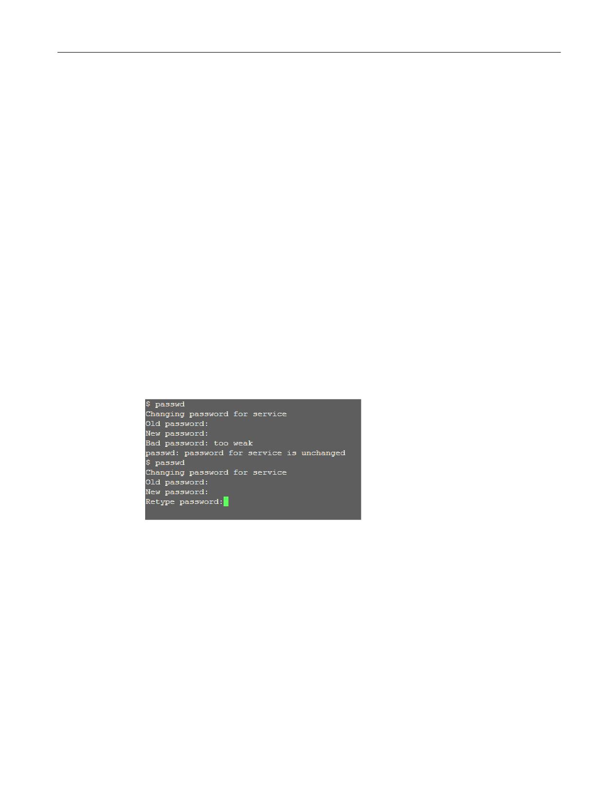
System settings
1.1 Delivery condition of the system
Rules relating to the password structure
The following rules must be observed when assigning a new password:
● Permissible (and specified) characters include lowercase letters, uppercase letters,
numbers and special characters.
● The password must have a minimum length of 6 characters. For each missing character
category (lowercase letters, uppercase letters, numbers and special characters), the
minimum length is extended by two characters.
Example: As a consequence, a password comprising only uppercase letters must be 12
characters long.
● It is not permissible that the password contains too many identical characters
● It is not permissible that the password has any similarity to the user name, the computer
name and the old password (e.g. write the password backwards, interchange uppercase/
lowercase letters).
If this rule is not complied with, then "too weak" message is output - and the old password
remains unchanged.
Changing the password
You can only change the user password with which you used to login; this means that if you
wish to change the passwords of all default users, then you must login with the particular login
one after the other.
Procedure:
1. Log into the basic NCU system (Linux) with user name and password.
2. Enter the "passwd" command.
3. Follow the instructions to enter the old, previous password.
4. Enter a new password and repeat this to confirm the password.
5. The new password is valid once all of the entries are correct. Any deviation means that the
dialog is exited, and the old password remains unchanged and valid.
NCU operating system
Commissioning Manual, 12/2019, A5E48312736B AA
7
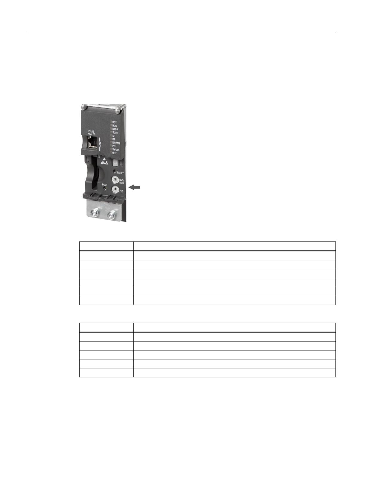
System settings
1.2 Meaning of switch positions
1.2
Meaning of switch positions
Diagnostic displays of the NCU
The NCU has two twist buttons in the lower section of the front panel.
Meaning of the settings on the SVC/NCK rotary switch:
Switch position
NC operating mode
0
NC normal run-up
1
Run-up of the NC with preset values (= memory reset)
2
Run-up of the NC with preset values; after powering up, the PLC is in RUN.
7
Debug mode (NC is not started)
8
IP address of the NCU is displayed on the seven-segment display.
All others
Not relevant
The settings on the PLC rotary switch have the same meaning as for a SIMATIC S7-CPU:
Switch position
Operating mode of the PLC
0
RUN
1
RUN (protected mode)
2
STOP
3
Memory reset (MRES)
All others
Not relevant
NCU operating system
8
Commissioning Manual, 12/2019, A5E48312736B AA
System settings
1.3 System booting
1.3
System booting
Sequence
To ensure unproblematic booting of the NCU, the CompactFlash Card must be inserted.
When the NCU is booting up, visual information on the current operating system is provided
using the following displays:
● The RDY-LED flashes slowly orange when the CF card is accessed.
● During booting, the 7-segment display outputs different codes that indicate, for example,
when the BIOS is started, when the CompactFlash Card is accessed, etc.
When the booting has been completed successfully, the following is displayed:
● The PLC LED lights up green.
● The 7-segment display shows "6." with a flashing dot.
● The RDY-LED lights up green, all other LEDs remain dark.
Performing a reset operation
The reset button is located behind the blanking plate of the NCU.
A reset operation resets the entire system and requires a system restart. This is comparable to
a "Power On reset" - except that the 24 V power supply does not have to be switched off.
Booting for servicing purposes
For service or diagnosis purposes, the NCU can be booted from a service system, the
Emergency Boot System.
See also
How do you create a service system for the NCU? (Page 63)
NCU operating system
Commissioning Manual, 12/2019, A5E48312736B AA
9

System settings
1.4 Displays during system booting
1.4
Displays during system booting
Behavior of the LEDs when booting
Of the LEDs on the front panel of the NCU, only the RDY LED and its status is important when
booting the NCU.
RDY LED
Additional LEDs
State/phase
7-segment display
Orange
Orange
BIOS boot
Post codes
See table: Load BIOS
Slowly flashing or-
Set from the PLC or
Booting up the kernel
1
ange (0.5 Hz)
option module
Phase 2: Initialization of the driver
Slowly flashing or-
Set from the PLC or
Booting the basic system
See table: Load the ba-
ange/green
option module
sic system
Phase 3: Initialization of the basic
(0.5 Hz)
system
OFF
Set from the PLC or
NRK/NCK outputs
See table: NRK/NCK
option module
outputs
green/red flashing
Set from the PLC or
Basic system shutdown
OFF
0.5 Hz)
option module
red
Set from the PLC or
Kernel shutdown
OFF
option module
red (5 Hz)
Set from the PLC or
SINAMICS fault
---
option module
SINAMICS faults and alarms, also see: SINAMICS S120/S150 List Manual (LH1)
Load BIOS
7-segment display
Meaning
00
Before loading the Master Boot Record (MBR) from the CompactFlash Card
01
Before starting the Master Boot Record (MBR) codes
02
Master Boot Record (MBR) code started
03
Second stage of the boot loader started, before reading the configuration file
04
Before loading the kernel
05
Before starting the kernel
Booting the basic system
See diagram: Meaning of switch positions (Page 8)
7-segment display
Meaning
1 (begin)
Basis initializations
2 (prepfs)
Cleaning up and preparing the file system
3 (hostname, loopback)
The name is set and the loopback interface configured.
4 (syslog)
Starting the system logging
Starting the CFS class 1, provide the network interfaces.
NCU operating system
10
Commissioning Manual, 12/2019, A5E48312736B AA

System settings
1.4 Displays during system booting
7-segment display
Meaning
5 (network)
Initializing the network interfaces and the firewall
6 (NCU:rtai, TCU:tcu-
Starting the time server (ntpd)
config)
7 (lsh)
Starting the SSH server (generate a host key if one is still not available).
8 (NCU:ftpd,
Starting the FTP server
TCU:mtouch)
9 (NCU:tcuservices,
Starting the TCU services (TFTP, VNC)
TCU:usbexport)
U r
Update required:
The CompactFlash card of the NCU contains a software version that is not
executable on type 3B modules and cannot be updated by an update.
Remedy:
● Check whether this CompactFlash card runs up in another NCU.
● Check whether the CompactFlash card is defective with the aid of a
service system: sc check-cf (Page 43)
The code "U r" can also be output in the following cases:
● No CompactFlash card is inserted.
● The CompactFlash card cannot be read.
● The partition table of the CompactFlash card is defective.
NRK/NCK outputs
See diagram: Meaning of switch positions (Page 8)
7-segment display
Meaning
1
Not applicable.
2
Not applicable.
3
Debugger was initialized.
4
NRK operating system was successfully activated.
5
NRK operating system has booted, init task is being processed (→ the appli-
cation boots).
6
Initialization was successfully performed; the control is in cyclic operation.
6.
with flashing point: The control is in cyclic operation and the cycles are active.
F
Internal error: Can only be read via additional diagnostics.
1 or 2
CompactFlash Card and SRAM data do not match. To resolve this problem,
a general reset is required by booting with switch position 1 or 2.
Lxx=yyy
Internal error when starting NCK, "xx" is the line number in the mcsystem.ini,
"yyy" is a unique error code for the code position.
NCU operating system
Commissioning Manual, 12/2019, A5E48312736B AA
11
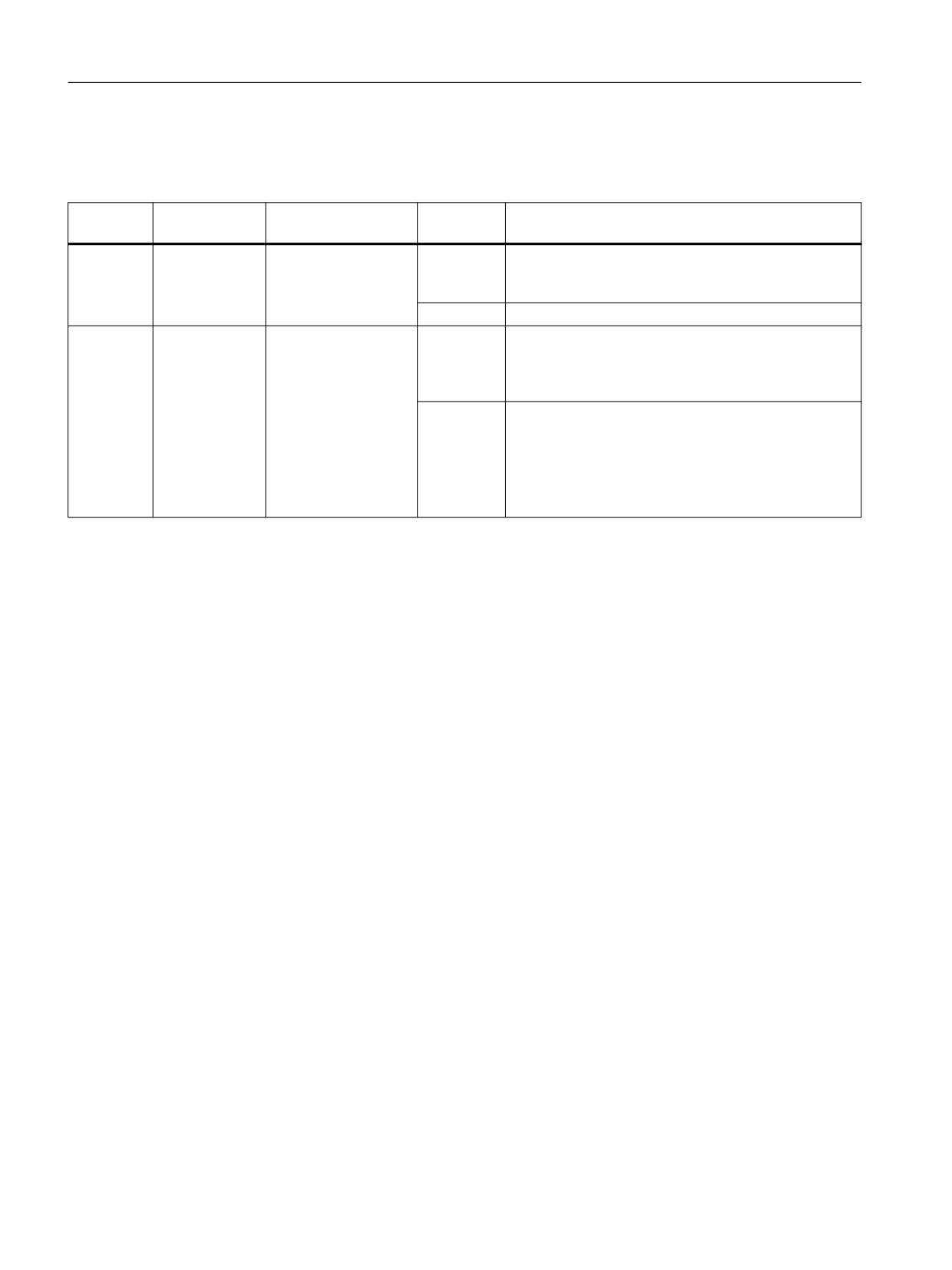
System settings
1.4 Displays during system booting
System error
See diagram: Meaning of switch positions (Page 8)
RDY LED
Additional
Meaning
7-segment
Meaning
LEDs
display
Rapidly
Set from the
Permanent error:
C
"crash": The operating system crashes (this approxi-
flashing
PLC or option
mately corresponds to a Blue Screen for Windows);
The system is stop-
red (2Hz)
module
details can be found in the system log file.
ped.
P
"partition": Error when repartitioning
Rapidly
Set from the
Temporary error:
E
"error": A read or write error has occurred on the Com-
flashing
PLC or option
pactFlash Card (an additional point is displayed for a
The system may con-
red/orange
module
write error). It is possible that the CompactFlash Card
tinue to run with re-
(2 Hz)
is defective and should be replaced.
stricted functions.
F
"full": The CompactFlash Card is too full, so it is prob-
able that not all of the services will be able to be suc-
cessfully started.
When booting, this error is displayed for 1 minute; the
system then continues to boot, however, it can be as-
sumed that problems will occur.
NCU operating system
12
Commissioning Manual, 12/2019, A5E48312736B AA
Configuring the system
2
2.1
Ethernet interfaces of the NCU
Supplementary conditions
For the operation of an NCU:
● No more than one NCU may be operated as a DHCP server on the system network.
● An external mouse is recommended when using the System Network Center.
Configuration of the interfaces
The following connections can be established via the Ethernet interfaces:
Interface
Labeling
Inter-
Terminal settings
nal
name
Ethernet IE1/OP
X120
(Eth 2)
Connection to the system network with preset IP address
192.168.214.1 with subnet screen form 255.255.255.0
and active DHCP server for SINUMERIK
Ethernet IE2/NET
X130
(Eth 1)
Connection to company network as standard DHCP client
Ethernet
X127
(Ibn 0)
Service terminal with fixed IP address 192.168.215.1 and
fixed subnet screen form 255.255.255.224 with active
DHCP server
Network interface
The network interface is an interface that enables network communication. These are the
Ethernet interfaces on the NCU.
VNC (Virtual Network Computing)
Virtual Network Computing is a software that displays the screen contents of a remote
computer, with a running VNC server, on a local computer, with a running VNC viewer, and in
return sends keyboard and mouse movements of the local computer to the remote computer.
NCU operating system
Commissioning Manual, 12/2019, A5E48312736B AA
13
Configuring the system
2.2 How to determine the IP address of the NCU
2.2
How to determine the IP address of the NCU
NCU in the system network (X120)
On the X120, the NCU is pre-selected as required: No settings are necessary.
NCU in the company network (X130)
On the X130, the NCU is set to the address reference via DHCP. If the company network has
a DHCP server no further settings are required.
Example: Determining the IP address
There are several possibilities for determining the address that the NCU obtained in the
company network:
● If the NCU boots in switch position 8, it shows the IP address on the X130 on the 7-segment
display.
● Once the NCU has booted successfully, open a service shell on the TCU and execute the
following command (Page 56) to obtain the desired information:
SC SHOW IP
If the company network has no available DHCP server or if this cannot be used, you are given
the option to set a fixed address for the NCU on the X130 (in accordance with the addresses
already used in the company network).
The following command displays the IP address on the X130:
SC SHOW IP -X130
Note
The IP addresses can also be set directly from the SINUMERIK Operate user interface in the
"Commissioning" → "Network" operating area.
NCU operating system
14
Commissioning Manual, 12/2019, A5E48312736B AA
Configuring the system
2.3 Configuration file "basesys.ini"
2.3
Configuration file "basesys.ini"
Storage path
For a Linux basic system, a template of the file is provided on the system CompactFlash card
under the following path:
siemens/system/etc/template-basesys.ini
Copy this template with the name basesys.ini into one of the following directories:
oem/system/etc/basesys.ini
user/system/etc/basesys.ini
Use
Settings are made in the basesys.ini file that specify the behavior of the system in the network.
To edit the basesys.ini file:
● Comments are introduced by ';' or '#' at the beginning of the line, and span the width of the
line. Empty lines are also handled as comments.
● The sections that start with a "[NAME]" line are ignored by the basic system itself, but are
sometimes used by the HMI.
● Variable definitions are written in the form "NAME=VALUE". Blanks are permitted around
the '=' character. The value may also be enclosed in double quotation marks, but this is
optional.
Note
Suitable editors for Linux
In most Linux system files, lines may only be ended with LF, and not with CRLF as in
Windows. Please take note of this when selecting an editor. The HMI application editor
under "Commissioning” is suitable.
In the Linux operating system, the UNIX editor vi is available.
Please take note that the Linux operating system is case-sensitive.
Reference
To make settings in the basesys.ini file, dialogs are provided in the "Commissioning" operating
area in SINUMERIK Operate in order to display or modify the values of the individual variables:
Commissioning Manual "SINUMERIK Operate" (IM9)
NCU operating system
Commissioning Manual, 12/2019, A5E48312736B AA
15
Configuring the system
2.3 Configuration file "basesys.ini"
2.3.1
Section [ExternalInterface]
Description
In this section, the parameters and settings for the external Ethernet interface are defined. For
an NCU7x0, this is X130 (Eth1). If the external interface is in DHCP mode, i.e. the value of
ExternalIP is empty or not defined, then all parameters listed here, with the exception of
"DHCPClientID", are accepted by the DHCP server as long as the server provides a value for
the parameter.
DisableCompanyNet
If this variable is set to 1, the X130 interface to the company network is not initialized and is thus
not available.
Value:
Empty, 0 or 1
Default:
Empty
ExternalIP
If ExternalIP is not empty, the fixed IP address specified there is used in the company network
interface. The ExternalNetMask then also needs to be set, as well as the gateway, name
servers, host name, and domain if required.
If ExternalIP is not set or is empty, a DHCP client is started on the interface.
Value:
IP address
Default:
Empty
ExternalNetMask
ExternalNetMask must be set together with ExternalIP, in order to define the size of the network.
Value:
Subnet mask
Default:
Empty
Gateway
If the value of gateway is not empty, the host specified there is used as the default gateway,
which means that all IP packets that cannot be directly assigned are sent there for routing.
If no gateway is specified, only the networks that are directly connected are accessible.
Value:
IP address
Default:
Empty
NCU operating system
16
Commissioning Manual, 12/2019, A5E48312736B AA
Configuring the system
2.3 Configuration file "basesys.ini"
Nameservers
If DNS name servers are specified here, then these must be used to resolve symbolic host
names, i.e. at most of the points where an IP address is expected, a computer name can also
be used instead.
The name server setting is also sent to your DHCP client (TCU, PG) via the DHCP server of the
NCU, so that this can also work with symbolic names.
Value:
List of IP addresses (separated by blanks)
Default:
Empty
Timeservers
Here you can specify a list of NTP servers (Network Time Protocol) that can be used by the
NTPD on the NCU for time synchronization. The status of NTPD is output in the system log file /
var/log/messages
As an alternative to the system log file, you can use "ntpq -p localhost" to find a time server
marked '*'. The time is synchronized with this server.
Value:
List of IP addresses (separated by blanks)
Default:
Empty
Note
Setting the time zone and the time server
The IP addresses can also be set directly from the SINUMERIK Operate user interface in the
"Commissioning" → "Date time >" softkey operating area.
Hostname
Here you can define a name for the local host. This manually assigned name takes priority over
all other names.
The host name is determined in the following order:
● Host name from the basesys.ini file, if set.
● A name received from the DHCP server (if DHCP client mode and a name have been
supplied), the result of a reverse DNS lookup, i.e. which name belongs to the IP received (if
name servers are defined).
● Default name ("NONAME_...")
Because the host name is also used as DNS name it must satisfy the corresponding
requirements of the RFC:
● ASCII letters (a-z, A-Z), numbers (0-9) and '-'
● max. 63 characters
Value:
Name
Default:
Empty
NCU operating system
Commissioning Manual, 12/2019, A5E48312736B AA
17
Configuring the system
2.3 Configuration file "basesys.ini"
Domain
These variables can be used to configure the DNS domain. The effect is that names in this
domain can be resolved without qualification (e.g. if the domain is "test.local", you can also
specify the name "computer1.test.local" as "computer1").
Value:
Name
Default:
Empty
DHCPClientID
With these variables, you can influence which ClientID the DHCP client presents to its server.
This ID can be used by the server to assign certain parameters to the client, for example a static
IP address.
Usually, the MAC address of the Ethernet interface is used for this purpose. This is also the
default setting. Alternatively, you can also use the host name ("@NAME"), which must then be
defined in the basesys.ini, in order to be recognized before the DHCP request. It is also possible
to use an arbitrary string for ClientID.
Value:
@MAC, @CFID, @NAME or any string
Default:
@MAC
2.3.2
Section [InternalInterface]
Description
In the section [InternalInterface] the data is specified for synchronization of the DHCP server in
the system network.
DisableSysNet
If this variable is set to 1, the X120 interface to the system network is not initialized and is thus
not available.
Value:
Empty, 0 or 1
Default:
Empty
InternalIP
Use this variable to set the fixed IP address in the system network. InternalIP should always be
used together with InternalNetMask.
Value:
IP address
Default:
192.168.214.1
NCU operating system
18
Commissioning Manual, 12/2019, A5E48312736B AA