Intel 64 and IA-32 Architectures. Software Developer’s Manual (2026) - page 66
INTEL® PROCESSOR TRACE
36.7.2.2 IA32_PERFEVTSELx MSR Changes
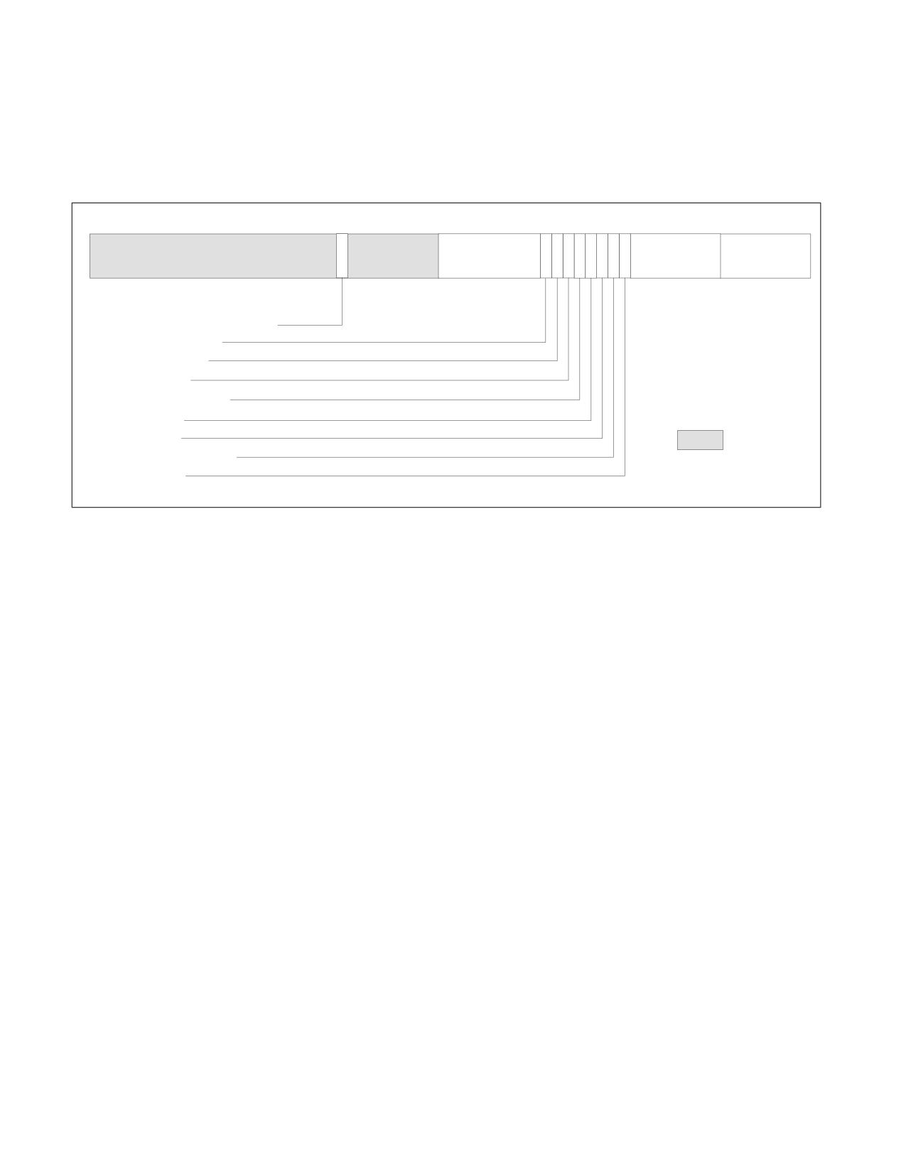
The IA32_PERFEVTSELx MSR is an existing MSR that describes a performance counter's configuration. When PT
Trigger Tracing is supported, a new bit 38 is defined as EN_PT_LOG. If EN_PT_LOG is set to 1, that performance
counter can be used as a trigger input in the IA32_RTIT_TRIGGERx_CFG.Input fields.
63
38
31
24 23 22 21 20 19 18 17 16 15
8
7
0
I
A
I
U
Counter Mask
E
P
O
Unit Mask
N
N
N
E
S
Event Select
(CMASK)
N
C
S
(UMASK)
V
Y
T
R
EN_PT_LOG-Enable as Trigger Input
INV-Invert Counter Mask
EN-Enable Counters
ANY-Any Thread
INT-APIC Interrupt Enable
PC-Pin Control
E-Edge Detect
Reserved
OS-Operating System Mode
USR-User Mode
Figure 36-4. Layout of the IA32_PERFEVTSELx MSR
36.7.2.3 DR7 Changes
The DR7 Debug Control Register is an existing architectural register that can be used for enabling debug breakpoint
matches. If an implementation supports DR Breakpoint Match as a PT Trigger Tracing trigger input, indicated by
CPUID.14H.01H:ECX[15]=1, then bits [35:32] of DR7 are described as DRx_PT_LOG bits, with the four bits corre-
sponding to DR0-3. Note that the upper bits of DR7 are changed by MOV to DR7 only in 64-bit mode.
36.7.2.4 IA32_RTIT_STATUS Changes
A new “Paused” bit is added to the IA32_RTIT_STATUS register as part of PT Trigger Tracing. Hardware sets this bit
when a PT Trigger Tracing paused trigger action occurs. Hardware clears this bit when a PT Trigger Tracing resume
trigger action occurs. The Paused bit has read/write semantics. Software that wants tracing to start only after
reaching a trigger can manually set Paused=1 before setting the TraceEn bit. When Paused=1, packets that depend
on FilterEn=1 will be suppressed. PacketEn has the following updated semantics:
PacketEn := BranchEn AND TriggerEn AND ContextEn AND FilterEn AND !Paused
Note that, as defined in Section 36.2.6.3, Paused bit transitions that result in PacketEn transitions will also cause
the hardware to generate PGE/PGD packets. Such PGE/PGD packets may have a small skid.
36.8
PACKET GENERATION SCENARIOS
The following tables provides examples of packet generation for various operations. The following acronyms are
used in the packet examples below:
• CLIP - Current LIP
• NLIP - Next Sequential LIP
• BLIP - Branch Target LIP
Table 36-59 illustrates the packets generated by a series of example operations, assuming that PacketEn
(TriggerEn && ContextEn && FilterEn && BranchEn) is set before and after the operation.
36-76
Vol. 3C

INTEL® PROCESSOR TRACE
Table 36-59. Packet Generation under Different Example Operations
Case
Operation
Details
Packets
1
Normal non-jump operation
None
2
Conditional branch
6th branch in internal TNT buffer
TNT
3
Conditional branch
None
1st..5th branch in internal TNT buffer
4
Near indirect JMP or CALL
TIP(BLIP)
5
Direct near JMP or CALL
None
6
Near RET
Uncompressed
TIP(BLIP)
7
Near RET
Compressed, 6th branch in internal TNT buffer
TNT
8
Far Branch
Assumes no update to CR3, CS.L, or CS.D
TIP(BLIP)
9
Far Branch
Assumes update to CR3
PIP(NewCR3), TIP(BLIP)
10
Far Branch
Assumes update to CR3 and CS.D/CS.L
PIP(NewCR3), MODE.Exec, TIP(BLIP)
11
External Interrupt or NMI
Assumes no update to CR3, CS.D, or CS.L
FUP(NLIP), TIP(BLIP)
12
External Interrupt or NMI
Assumes update to CR3 and CS.D/CS.L
FUP(NLIP), PIP(NewCR3),
MODE.Exec, TIP(BLIP)
13
Exception/Fault or Software Interrupt
Assumes no update to CR3, CS.D, or CS.L
FUP(CLIP), TIP(BLIP)
14
MOV to CR3
PIP(NewCR3, NR)
15
VM exit
Assumes system-wide tracing, see Section
See Table 36-53
36.5.2.1
16
VM entry
Assumes system-wide tracing, see Section
See Table 36-53
36.5.2.1
17
ENCLU[EENTER] / ENCLU[ERESUME] /
Only debug enclaves allow PacketEn to be set
FUP(CLIP), TIP(BLIP)
ENCLU[EEXIT] / AEX/EEE
during enclave execution. Assumes no change
to CS.L or CS.D.
18
XBEGIN/XACQUIRE/XEND/XRELEASE
Does not begin/end transactional execution
None
19
XBEGIN/XACQUIRE
Assumes beginning of transactional execution
MODE.TSX(InTX=1, TXAbort=0),
FUP(CLIP)
20
XEND/XRELEASE
Completes transaction
MODE.TSX(InTX=0, TXAbort=0),
FUP(CLIP)
21
XABORT or Asynchronous Abort
Aborts transactional execution
MODE.TSX(InTX=0, TXAbort=1),
FUP(CLIP), TIP(BLIP)
22
INIT
On BSP. Assumes no CR3, CS.D, or CS.L update.
FUP(NLIP), TIP(ResetLIP)
23
INIT
On AP, goes to wait-for-SIPI. Assumes no CR3
FUP(NLIP)
update.
24
SIPI
Assumes no CS.D or CS.L update
TIP.PGE(SIPI.LIP)
25
Wake from state deeper than C0.1, P-
TSC?, TMA?, CBR
TSC if TSCEn=1
state change, or other scenario where
TMA if TSCEn=MTCEn=1
timing packets (MTC, CYC) may have
ceased.
26
UINTR
User interrupt handler entry.
FUP(NLIP), TIP(BLIP)
27
UIRET
Exiting from user interrupt handler.
TIP(BLIP)
Table 36-60 illustrates the packets generated in example scenarios where the operation alters the value of
PacketEn. Note that insertion of PSB+ is not included here, though it can be coincident with initial enabling of Intel
PT. See Section 36.3.7 for details.
Vol. 3C
36-77

INTEL® PROCESSOR TRACE
Table 36-60. Packet Generation with Operations That Alter the Value of PacketEn
Case
Operation
PktEn
PktEn
CntxEn
Details
Packets
Before
After
After
1
WRMSR/XRSTORS that
0
1
0
TSC if TSCEn=1;
TSC?, TMA?, CBR, MODE.Exec
changes TraceEn 0 → 1
TMA if TSCEn=MTCEn=1
2
WRMSR/XRSTORS that
0
1
1
TSC if TSCEn=1;
TSC?, TMA?, CBR, MODE.Exec,
changes TraceEn 0 → 1
TMA if TSCEn=MTCEn=1
TIP.PGE(NLIP)
3
WRMSR that changes Tra-
1
0
D.C.
FUP(CLIP), TIP.PGD()
ceEn 1 → 0
4
Taken Branch
1
0
1
Source is in IP filter region.
TIP.PGD(BLIP)
Target is outside IP filter region.
5
Taken Branch, Interrupt,
0
1
1
Source is outside IP filter region.
TIP.PGE(BLIP)
EEXIT, etc.
Target is in IP filter region.
6
Far Branch, Interrupt, EEN-
1
0
0
Requires change to CPL or CR3,
TIP.PGD()
TER, etc.
or entry to opt-out enclave.
7
Trap-like event (external
1
0
0
Requires change to CPL or CR3.
FUP(NLIP), TIP.PGD()
interrupt, NMI, VM exit/entry,
etc.)
8
Fault-like event (excep-
1
0
0
Requires change to CPL or CR3.
FUP(CLIP), TIP.PGD()
tion/fault, software inter-
rupt, VM exit/entry, etc.)
9
SMI, VM exit/entry
1
0
0
TraceEn is cleared.
FUP(NLIP), TIP.PGD()
10
RSM, VM exit/entry
0
1
1
TraceEn is set.
See Case 2 for packets on
enable. FUP/TIP.PGE IP is the
BLIP.
11
VM Exit
1
0
0
Assumes guest-only tracing, see
FUP(VMCSg.RIP), TIP.PGD()
Section 36.5.2.2.
TraceEn is cleared.
12
VM entry
0
1
1
Assumes guest-only tracing, see
TIP.PGE(VMCSg.RIP)
Section 36.5.2.2.
TraceEn is set.
Table 36-61 illustrates examples of PTWRITE, assuming TriggerEn && PTWEn is true.
Table 36-61. Examples of PTWRITE when TriggerEn && PTWEn is True
Case
Operation
ContextEn
Details
Packets
1
MWAIT/UMWAIT gets fault or VM exit.
D.C.
None.
Other trace sources may generate pack-
ets on fault or VM exit.
2
MWAIT/UMWAIT requests C0, or moni-
D.C.
None.
tor not armed, or VMX virtual-interrupt
delivery.
3
MWAIT/UMWAIT enters C-state deeper
0
PWRE(Cx), EXSTOP
than C0.1.
4
MWAIT/UMWAIT enters C-state deeper
1
MWAIT(Cy), PWRE(Cx), EXSTOP(IP),
than C0.1.
FUP(CLIP)
5
HLT, Triple-fault shutdown, other oper-
1
PWRE(C1), EXSTOP(IP), FUP(CLIP)
ation that enters C1.
36-78
Vol. 3C

INTEL® PROCESSOR TRACE
Table 36-61. Examples of PTWRITE when (Contd.)TriggerEn && PTWEn is True
Case
Operation
ContextEn
Details
Packets
6
Hardware Duty Cycling (HDC).
1
TSC if TSCEn=1
PWRE(HW, C6), EXSTOP(IP), FUP(NLIP),
TMA if TSCEn=MTCEn=1
TSC?, TMA?, CBR, PWRX(CC6, CC6, 0x8)
7
Wake event during Cx (x > 0).
D.C.
TSC if TSCEn=1
TSC?, TMA?, CBR, PWRX(LCC, DCC, 0x1)
TMA if TSCEn=MTCEn=1
Other trace sources may generate pack-
ets for the wake operation (e.g., inter-
rupt).
Table 36-62 illustrates examples of Power Event Trace, assuming TriggerEn && PwrEvtEn is true.
Table 36-62. Examples of Power Event Trace when TriggerEn && PwrEvtEn is True
Case
Operation
ContextEn
Details
Packets
&&
FilterEn
1
PTWRITE rm32/64
0
None
2
PTWRITE rm32
1
FUP, PTW.IP=1 if FUPonPTW=1
PTW(IP=1?, 4B, rm32_value),
FUP(CLIP)?
3
PTWRITE rm64
1
FUP, PTW.IP=1 if FUPonPTW=1
PTW(IP=1?, 8B, rm64_value),
FUP(CLIP)?
Table 36-63 illustrates examples of Event Trace, assuming TriggerEn && ContextEn && EventEn is true. In all cases,
other trace sources (e.g., BranchEn), if enabled, may generate additional packets. For details, see the other tables
in this section.
Table 36-63. Event Trace Examples when TriggerEn && ContextEn && EventEn is True
Case
Operation
ContextEn
ContextEn
Details
Packets
Before
After
1
IRET, ERETS, ERETU
1
D.C.
CFE.IRET(IP=1), FUP(CLIP)
2
IRET, ERETS, ERETU
0
1
CFE(IRET)
3
External interrupt, including
1
D.C.
CFE.INTR(IP=1, Vector), FUP(NLIP)
NMI
4
External interrupt, including
1
1
Assumes BranchEn=1,
CFE.INTR(IP=0, Vector), FUP(NLIP),
NMI
illustrates the shared FUP.
TIP(BLIP)
5
SW Interrupt (without FRED),
1
D.C.
CFE.INTR(IP=1, Vector), FUP(CLIP)
Exception/Fault other than
#PF
6
Page Fault (#PF)
1
D.C.
EVD.PFA, CFE.INTR(IP=1,14),
FUP(CLIP)
7
Page Fault (#PF)
0
D.C.
None
10
SMI
1
D.C.
CFE.SMI(IP=1), FUP(NLIP)
11
RSM, TraceEn restored to 1
D.C.
1
CFE.RSM(IP=0)
12
Entry to Shutdown
1
D.C.
CFE.SHUTDOWN(IP=1), FUP(CLIP)
13
VM exit caused by interrupt,
1
D.C.
Assumes “Conceal VMX in
EVD.VMXQ, EVD.VMXR, CFE.VMEX-
fault, or SMI
PT” exit control is 0.
IT_INTR(IP=1, Vector),
FUP(VMCSg.LIP)
14
VM exit caused by other than
1
D.C.
Assumes “Conceal VMX in
EVD.VMXQ, EVD.VMXR,
interrupt, fault, or SMI
PT” exit control is 0.
CFE.VMEXIT(IP=1), FUP(VMCSg.LIP)
Vol. 3C
36-79

INTEL® PROCESSOR TRACE
Table 36-63. Event Trace Examples when TriggerEn && ContextEn && EventEn is True
Case
Operation
ContextEn
ContextEn
Details
Packets
Before
After
15
VM exit caused by other than
0
1
Assumes “Conceal VMX in
CFE.VMEXIT(IP=0)
interrupt, fault, or SMI
PT” exit control is 0.
16
VM entry
1
D.C.
Assumes “Conceal VMX in
CFE.VMENTRY(IP=1), FUP(VMCSh.LIP)
PT” entry control is 0.
17
AEX/EEE, from opt-out (non-
0
0
None
debug) enclave
18
AEX/EEE, from opt-out (non-
0
1
CFE.INTR(IP=0)
debug) enclave
19
AEX, from opt-in (debug)
1
D.C.
CFE.INTR(IP=1, Vec), FUP(AEP LIP)
enclave
20
INIT
1
D.C.
CFE.INIT(IP=1), FUP(NLIP)
21
SIPI
1
D.C.
CFE.SIPI(IP=0)
22
STI/CLI/POPF
1
1
Assumes a change to
MODE.Exec, FUP(NLIP)
RFLAGS.IF.
23
SW Interrupt (with FRED)
1
D.C.
CFE.SWINTR(IP=1, Vector), FUP(CLIP)
24
SYSCALL, SYSENTER (with
1
D.C.
CFE.SYSCALL(IP=1), FUP(CLIP)
FRED)
36.9
SOFTWARE CONSIDERATIONS
36.9.1 Tracing SMM Code
Nothing prevents an SMM handler from configuring and enabling packet generation for its own use. As described in
Section Section 36.2.9.3, SMI will always clear TraceEn, so the SMM handler would have to set TraceEn in order to
enable tracing. There are some unique aspects and guidelines involved with tracing SMM code, which follow:
1. SMM should save away the existing values of any configuration MSRs that SMM intends to modify for tracing.
This will allow the non-SMM tracing context to be restored before RSM.
2. It is recommended that SMM wait until it sets CSbase to 0 before enabling packet generation, to avoid possible
LIP vs RIP confusion.
3. Packet output cannot be directed to SMRR memory, even while tracing in SMM.
4. Before performing RSM, SMM should take care to restore modified configuration MSRs to the values they had
immediately after #SMI. This involves first disabling packet generation by clearing TraceEn, then restoring any
other configuration MSRs that were modified.
5. RSM
- Software must ensure that TraceEn=0 at the time of RSM. Tracing RSM is not a supported usage model, and
the packets generated by RSM are undefined.
- For processors on which Intel PT and LBR use are mutually exclusive (see Section 36.3.1.2), any RSM
during which TraceEn is restored to 1 will suspend any LBR or BTS logging.
36-80
Vol. 3C
INTEL® PROCESSOR TRACE
36.9.2 Cooperative Transition of Multiple Trace Collection Agents
A third-party trace-collection tool should take into consideration the fact that it may be deployed on a processor
that supports Intel PT but may run under any operating system.
In such a deployment scenario, Intel recommends that tool agents follow similar principles of cooperative transition
of single-use hardware resources, similar to how performance monitoring tools handle performance monitoring
hardware:
• Respect the “in-use” ownership of an agent who already configured the trace configuration MSRs, see architec-
tural MSRs with the prefix “IA32_RTIT_” in Chapter 2, “Model-Specific Registers (MSRs)‚” in the Intel® 64 and
IA-32 Architectures Software Developer’s Manual, Volume 4, where “in-use” can be determined by reading the
“enable bits” in the configuration MSRs.
• Relinquish ownership of the trace configuration MSRs by clearing the “enabled bits” of those configuration
MSRs.
36.9.3 Tracking Time
This section describes the relationships of several clock counters whose update frequencies reside in different
domains that feed into the timing packets. To track time, the decoder also needs to know the regularity or irregu-
larity of the occurrences of various timing packets that store those clock counters.
Intel PT provides time information for three different but related domains:
• Processor timestamp counter
This counter increments at the max non-turbo or P1 frequency, and its value is returned on a RDTSC. Its
frequency is fixed. The TSC packet holds the lower 7 bytes of the timestamp counter value. The TSC packet
occurs occasionally and are much less frequent than the frequency of the time stamp counter. The timestamp
counter will continue to increment when the processor is in deep C-States, with the exception of processors
reporting CPUID.80000007H:EDX.TSC_INVARIANT[8] =0.
• Core crystal clock
The ratio of the core crystal clock to timestamp counter frequency is known as P, and can be calculated as
CPUID.15H:EBX[31:0] / CPUID.15H:EAX[31:0]. The frequency of the core crystal clock is fixed and lower
than that of the timestamp counter. The periodic MTC packet is generated based on software-selected
multiples of the crystal clock frequency. The MTC packet is expected to occur more frequently than the TSC
packet.
• Processor core clock
The processor core clock frequency can vary due to P-state and thermal conditions. The CYC packet provides
elapsed time as measured in processor core clock cycles relative to the last CYC packet.
A decoder can use all or some combination of these packets to track time at different resolutions throughout the
trace packets.
36.9.3.1 Time Domain Relationships
The three domains are related by the following formula:
TimeStampValue = (CoreCrystalClockValue * P) + AdjustedProcessorCycles + Software_Offset;
The CoreCrystalClockValue, also known as the Always Running Timer (ART) value, can provide the coarse-grained
component of the TSC value. P, or the TSC/ART ratio, can be derived from CPUID.15H, as described in Section
36.9.3.
The AdjustedProcessorCycles component provides the fine-grained distance from the rising edge of the last core
crystal clock. Specifically, it is a cycle count in the same frequency as the timestamp counter from the last crystal
clock rising edge. The value is adjusted based on the ratio of the processor core clock frequency to the Maximum
Non-Turbo (or P1) frequency.
The Software_Offsets component includes software offsets that are factored into the timestamp value, such as
IA32_TSC_ADJUST.
Vol. 3C
36-81
INTEL® PROCESSOR TRACE
36.9.3.2 Estimating TSC within Intel PT
For many usages, it may be useful to have an estimated timestamp value for all points in the trace. The formula
provided in Section 36.9.3.1 above provides the framework for how such an estimate can be calculated from the
various timing packets present in the trace.
The TSC packet provides the precise timestamp value at the time it is generated; however, TSC packets are infre-
quent, and estimates of the current timestamp value based purely on TSC packets are likely to be very inaccurate
for this reason. In order to get more precise timing information between TSC packets, CYC packets and/or MTC
packets should be enabled.
MTC packets provide incremental updates of the CoreCrystalClockValue. On processors that support CPUID.15H,
the frequency of the timestamp counter and the core crystal clock is fixed, thus MTC packets provide a means to
update the running timestamp estimate. Between two MTC packets A and B, the number of crystal clock cycles
passed is calculated from the 8-bit payloads of respective MTC packets:
(CTCB - CTCA), where CTCi = MTCi[15:8] << IA32_RTIT_CTL.MTCFreq and i = A, B.
The time from a TSC packet to the subsequent MTC packet can be calculated using the TMA packet that follows the
TSC packet. The TMA packet provides both the crystal clock value (lower 16 bits, in the CTC field) and the Adjust-
edProcessorCycles value (in the FastCounter field) that can be used in the calculation of the corresponding core
crystal clock value of the TSC packet.
When the next MTC after a pair of TSC/TMA is seen, the number of crystal clocks passed since the TSC packet can
be calculated by subtracting the TMA.CTC value from the time indicated by the MTCNext packet by
CTCDelta[15:0] = (CTCNext[15:0] - TMA.CTC[15:0]), where CTCNext = MTCPayload << IA32_RTIT_CTL.MTCFreq.
The TMA.FastCounter field provides the number of AdjustedProcessorCycles since the last crystal clock rising edge,
from which it can be determined the percentage of the next crystal clock cycle that had passed at the time of the
TSC packet.
CYC packets can provide further precision of an estimated timestamp value to many non-timing packets, by
providing an indication of the time passed between other timing packets (MTCs or TSCs).
When enabled, CYC packets are sent preceding each CYC-eligible packet, and provide the number of processor core
clock cycles that have passed since the last CYC packet. Thus between MTCs and TSCs, the accumulated CYC
values can be used to estimate the AdjustedProcessorCycles component of the timestamp value. The accumulated
CPU cycles will have to be adjusted to account for the difference in frequency between the processor core clock and
the P1 frequency. The necessary adjustment can be estimated using the core:bus ratio value given in the CBR
packet, by multiplying the accumulated cycle count value by P1/CBRpayload.
Note that stand-alone TSC packets (that is, TSC packets that are not a part of a PSB+) are typically generated only
when generation of other timing packets (MTCs and CYCs) has ceased for a period of time. Example scenarios
include when Intel PT is re-enabled, or on wake after a sleep state. Thus any calculated estimate of the timestamp
value leading up to a TSC packet will likely result in a discrepancy, which the TSC packet serves to correct.
A greater level of precision may be achieved by calculating the CPU clock frequency, see Section 36.9.3.4 below for
a method to do so using Intel PT packets.
CYCs can be used to estimate time between TSCs even without MTCs, though this will likely result in a reduction in
estimated TSC precision.
36.9.3.3 VMX TSC Manipulation
When software executes in non-Root operation, additional offset and scaling factors may be applied to the TSC
value. These are optional, but may be enabled via VMCS controls on a per-VM basis. See Chapter 28, “VMX Non-
Root Operation‚” for details on VMX TSC offsetting and TSC scaling.
Like the value returned by RDTSC, TSC packets will include these adjustments, but other timing packets (such as
MTC, CYC, and CBR) are not impacted. In order to use the algorithm above to estimate the TSC value when TSC
scaling is in use, it will be necessary for software to account for the scaling factor. See Section 36.5.2.4 for details.
36.9.3.4 Calculating Frequency with Intel PT
Because Intel PT can provide both wall-clock time and processor clock cycle time, it can be used to measure the
processor core clock frequency. Either TSC or MTC packets can be used to track the wall-clock time. By using CYC
36-82
Vol. 3C
INTEL® PROCESSOR TRACE
packets to count the number of processor core cycles that pass in between a pair of wall-clock time packets, the
ratio between processor core clock frequency and TSC frequency can be derived. If the P1 frequency is known, it
can be applied to determine the CPU frequency. See Section 36.9.3.1 above for details on the relationship between
TSC, MTC, and CYC.
Vol. 3C
36-83
INTEL® PROCESSOR TRACE
36-84
Vol. 3C
INTRODUCTION TO INTEL® SOFTWARE GUARD EXTENSIONS
CHAPTER 37
INTRODUCTION TO INTEL® SOFTWARE GUARD EXTENSIONS
37.1
OVERVIEW
Intel® Software Guard Extensions (Intel® SGX) is a set of instructions and mechanisms for memory accesses
added to Intel® Architecture processors. Intel SGX can encompass two collections of instruction extensions,
referred to as SGX1 and SGX2, see Table 37-1 and Table 37-2. The SGX1 extensions allow an application to instan-
tiate a protected container, referred to as an enclave. The enclave is a trusted area of memory, where critical
aspects of the application functionality have hardware-enhanced confidentiality and integrity protections. New
access controls to restrict access to software not resident in the enclave are also introduced. The SGX2 extensions
allow additional flexibility in runtime management of enclave resources and thread execution within an enclave.
Chapter 38 covers main concepts, objects and data structure formats that interact within the Intel SGX architec-
ture. Chapter 39 covers operational aspects ranging from preparing an enclave, transferring control to enclave
code, and programming considerations for the enclave code and system software providing support for enclave
execution. Chapter 40 describes the behavior of Asynchronous Enclave Exit (AEX) caused by events while
executing enclave code. Chapter 41 covers the syntax and operational details of the instruction and associated leaf
functions available in Intel SGX. Chapter 42 describes interaction of various aspects of IA32 and Intel® 64 archi-
tectures with Intel SGX. Chapter 43 covers Intel SGX support for application debug, profiling, and performance
monitoring.
OS
Entry Table
Enclave
Enclave Heap
Enclave Stack
App Code
Enclave Code
App Code
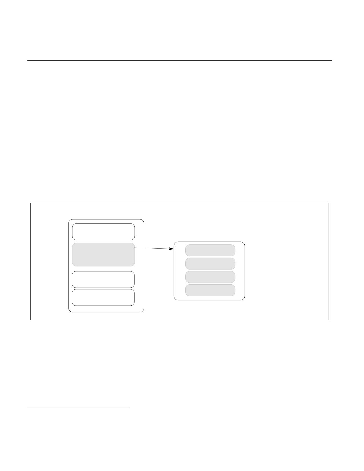
Figure 37-1. An Enclave Within the Application’s Virtual Address Space
37.2
ENCLAVE INTERACTION AND PROTECTION
Intel SGX allows the protected portion of an application to be distributed in the clear. Before the enclave is built, the
enclave code and data are free for inspection and analysis. The protected portion is loaded into an enclave where
its code and data is measured. Once the application’s protected portion of the code and data are loaded into an
enclave, memory access controls are in place to restrict access by external software. An enclave can prove its iden-
tity to a remote party and provide the necessary building-blocks for secure provisioning of keys and credentials.
The application can also request an enclave-specific and platform-specific key that it can use to protect keys and
data that it wishes to store outside the enclave.1
1. For additional information, see white papers on Intel SGX at https://www.intel.com/content/www/us/en/developer/tools/isa-exten-
sions/overview.html.
Vol. 3D
37-1
INTRODUCTION TO INTEL® SOFTWARE GUARD EXTENSIONS
Intel SGX introduces two significant capabilities to the Intel Architecture. First is the change in enclave memory
access semantics. The second is protection of the address mappings of the application.
37.3
ENCLAVE LIFE CYCLE
Enclave memory management is divided into two parts: address space allocation and memory commitment.
Address space allocation is the specification of the range of linear addresses that the enclave may use. This range
is called the ELRANGE. No actual resources are committed to this region. Memory commitment is the assignment
of actual memory resources (as pages) within the allocated address space. This two-phase technique allows flexi-
bility for enclaves to control their memory usage and to adjust dynamically without overusing memory resources
when enclave needs are low. Commitment adds physical pages to the enclave. An operating system may support
separate allocate and commit operations.
During enclave creation, code and data for an enclave are loaded from a clear-text source, i.e., from non-enclave
memory.
Untrusted application code starts using an initialized enclave typically by using the EENTER leaf function provided
by Intel SGX to transfer control to the enclave code residing in the protected Enclave Page Cache (EPC). The
enclave code returns to the caller via the EEXIT leaf function. Upon enclave entry, control is transferred by hard-
ware to software inside the enclave. The software inside the enclave switches the stack pointer to one inside the
enclave. When returning back from the enclave, the software swaps back the stack pointer then executes the
EEXIT leaf function.
On processors that support the SGX2 extensions, an enclave writer may add memory to an enclave using the SGX2
instruction set, after the enclave is built and running. These instructions allow adding additional memory resources
to the enclave for use in such areas as the heap. In addition, SGX2 instructions allow the enclave to add new
threads to the enclave. The SGX2 features provide additional capabilities to the software model without changing
the security properties of the Intel SGX architecture.
Calling an external procedure from an enclave could be done using the EEXIT leaf function. Software would use
EEXIT and a software convention between the trusted section and the untrusted section.
An active enclave consumes resources from the Enclave Page Cache (EPC, see Section 37.5). Intel SGX provides
the EREMOVE instruction that an EPC manager can use to reclaim EPC pages committed to an enclave. The EPC
manager uses EREMOVE on every enclave page when the enclave is torn down. After successful execution of
EREMOVE the EPC page is available for allocation to another enclave.
37.4
DATA STRUCTURES AND ENCLAVE OPERATION
There are 2 main data structures associated with operating an enclave, the SGX Enclave Control Structure (SECS,
see Section 38.7) and the Thread Control Structure (TCS, see Section 38.8).
There is one SECS for each enclave. The SECS contains meta-data about the enclave which is used by the hardware
and cannot be directly accessed by software. Included in the SECS is a field that stores the enclave build measure-
ment value. This field, MRENCLAVE, is initialized by the ECREATE instruction and updated by every EADD and
EEXTEND. It is locked by EINIT.
Every enclave contains one or more TCS structures. The TCS contains meta-data used by the hardware to save and
restore thread specific information when entering/exiting the enclave. There is one field, FLAGS, that may be
accessed by software. This field can only be accessed by debug enclaves. The flag bit, DBGOPTIN, allows to single
step into the thread associated with the TCS. (see Section 38.8.1)
The SECS is created when ECREATE (see Table 37-1) is executed. The TCS can be created using the EADD instruc-
tion or the SGX2 instructions (see Table 37-2).
37.5
ENCLAVE PAGE CACHE
The Enclave Page Cache (EPC) is the secure storage used to store enclave pages when they are a part of an
executing enclave. For an EPC page, hardware performs additional access control checks to restrict access to the
page. After the current page access checks and translations are performed, the hardware checks that the EPC page
37-2
Vol. 3D

INTRODUCTION TO INTEL® SOFTWARE GUARD EXTENSIONS
is accessible to the program currently executing. Generally an EPC page is only accessed by the owner of the
executing enclave or an instruction which is setting up an EPC page
The EPC is divided into EPC pages. An EPC page is 4KB in size and always aligned on a 4KB boundary.
Pages in the EPC can either be valid or invalid. Every valid page in the EPC belongs to one enclave instance. Each
enclave instance has an EPC page that holds its SECS. The security metadata for each EPC page is held in an
internal micro-architectural structure called Enclave Page Cache Map (EPCM, see Section 37.5.1).
The EPC is managed by privileged software. Intel SGX provides a set of instructions for adding and removing
content to and from the EPC. The EPC may be configured by BIOS at boot time. On implementations in which EPC
memory is part of system DRAM, the contents of the EPC are protected by an encryption engine.
37.5.1 Enclave Page Cache Map (EPCM)
The EPCM is a secure structure used by the processor to track the contents of the EPC. The EPCM holds one entry
for each page in the EPC. The format of the EPCM is micro-architectural, and consequently is implementation
dependent. However, the EPCM contains the following architectural information:
• The status of EPC page with respect to validity and accessibility.
• An SECS identifier (see Section 38.20) of the enclave to which the page belongs.
• The type of page: regular, SECS, TCS or VA.
• The linear address through which the enclave is allowed to access the page.
• The specified read/write/execute permissions on that page.
The EPCM structure is used by the CPU in the address-translation flow to enforce access-control on the EPC pages.
The EPCM structure is described in Table 38-28, and the conceptual access-control flow is described in Section
38.5.
The EPCM entries are managed by the processor as part of various instruction flows.
37.6
ENCLAVE INSTRUCTIONS AND INTEL® SGX
The enclave instructions available with Intel SGX are organized as leaf functions under three instruction
mnemonics: ENCLS (ring 0) and ENCLU (ring 3). Each leaf function uses EAX to specify the leaf function index, and
may require additional implicit input registers as parameters. The use of EAX is implied implicitly by the ENCLS and
ENCLU instructions; ModR/M byte encoding is not used with ENCLS and ENCLU. The use of additional registers does
not use ModR/M encoding and is implied implicitly by the respective leaf function index.
Each leaf function index is also associated with a unique, leaf-specific mnemonic. A long-form expression of Intel
SGX instruction takes the form of ENCLx[LEAF_MNEMONIC], where ‘x’ is either ‘S’, ‘U’, or ‘V’. The long-form
expression provides clear association of the privilege-level requirement of a given “leaf mnemonic”. For simplicity,
the unique “Leaf_Mnemonic” name is used (omitting the ENCLx for convenience) throughout in this document.
Details of individual SGX leaf functions are described in Chapter 41. Table 37-1 provides a summary of the instruc-
tion leaves that are available in the initial implementation of Intel SGX, which is introduced in the 6th generation
Intel Core processors. Table 37-2 summarizes enhancement of Intel SGX for future Intel processors.
Table 37-1. Supervisor and User Mode Enclave Instruction Leaf Functions in Long-Form of SGX1
Supervisor Instruction
Description
User Instruction
Description
ENCLS[EADD]
Add an EPC page to an enclave.
ENCLU[EENTER]
Enter an enclave.
ENCLS[EBLOCK]
Block an EPC page.
ENCLU[EEXIT]
Exit an enclave.
ENCLS[ECREATE]
Create an enclave.
ENCLU[EGETKEY]
Create a cryptographic key.
ENCLS[EDBGRD]
Read data from a debug enclave by debug-
ENCLU[EREPORT]
Create a cryptographic report.
ger.
ENCLS[EDBGWR]
Write data into a debug enclave by debug-
ENCLU[ERESUME]
Re-enter an enclave.
ger.
Vol. 3D
37-3

INTRODUCTION TO INTEL® SOFTWARE GUARD EXTENSIONS
Table 37-1. Supervisor and User Mode Enclave Instruction Leaf Functions in Long-Form of SGX1
Supervisor Instruction
Description
User Instruction
Description
ENCLS[EEXTEND]
Extend EPC page measurement.
ENCLS[EINIT]
Initialize an enclave.
ENCLS[ELDB]
Load an EPC page in blocked state.
ENCLS[ELDU]
Load an EPC page in unblocked state.
ENCLS[EPA]
Add an EPC page to create a version array.
ENCLS[EREMOVE]
Remove an EPC page from an enclave.
ENCLS[ETRACK]
Activate EBLOCK checks.
ENCLS[EWB]
Write back/invalidate an EPC page.
Table 37-2. Supervisor and User Mode Enclave Instruction Leaf Functions in Long-Form of SGX2
Supervisor Instruction
Description
User Instruction
Description
ENCLS[EAUG]
Allocate EPC page to an existing enclave.
ENCLU[EACCEPT]
Accept EPC page into the enclave.
ENCLS[EMODPR]
Restrict page permissions.
ENCLU[EMODPE]
Enhance page permissions.
ENCLS[EMODT]
Modify EPC page type.
ENCLU[EACCEPTCOPY]
Copy contents to an augmented EPC
page and accept the EPC page into
the enclave.
37.7
DISCOVERING SUPPORT FOR INTEL® SGX AND ENABLING ENCLAVE
INSTRUCTIONS
Detection of support of Intel SGX and enumeration of available and enabled Intel SGX resources are queried using
the CPUID instruction. The enumeration interface comprises the following:
• Processor support of Intel SGX is enumerated by a feature flag in CPUID.07H: CPUID.07H.00H:EBX.SGX[2]. If
CPUID.07H.00H:EBX.SGX = 1, the processor has support for Intel SGX, and requires opt-in enabling by BIOS
via IA32_FEATURE_CONTROL MSR.
If CPUID.07H.00H:EBX.SGX = 1, CPUID will report via the available sub-leaves of CPUID.12H on available
and/or configured Intel SGX resources.
• The available and configured Intel SGX resources enumerated by the sub-leaves of CPUID.12H depend on the
state of BIOS configuration.
37.7.1 Intel® SGX Opt-In Configuration
On processors that support Intel SGX, IA32_FEATURE_CONTROL provides the SGX_ENABLE field (bit 18). Before
system software can configure and enable Intel SGX resources, BIOS is required to set IA32_FEATURE_CON-
TROL.SGX_ENABLE = 1 to opt-in the use of Intel SGX by system software.
The semantics of setting SGX_ENABLE follows the rules of IA32_FEATURE_CONTROL.LOCK (bit 0). Software is
considered to have opted into Intel SGX if and only if IA32_FEATURE_CONTROL.SGX_ENABLE and IA32_FEA-
TURE_CONTROL.LOCK are set to 1. The setting of IA32_FEATURE_CONTROL.SGX_ENABLE (bit 18) is not reflected
by CPUID.
Table 37-3. Intel® SGX Opt-in and Enabling Behavior
CPUID.07H.00H:EBX.
FEATURE_CONTROL.
FEATURE_CONTROL.
CPUID.12H
Enclave Instruction
SGX
LOCK
SGX_ENABLE
0
Invalid
X
X
#UD
1
Valid*
X
X
#UD**
37-4
Vol. 3D

INTRODUCTION TO INTEL® SOFTWARE GUARD EXTENSIONS
Table 37-3. Intel® SGX Opt-in and Enabling Behavior
CPUID.07H.00H:EBX.
FEATURE_CONTROL.
FEATURE_CONTROL.
CPUID.12H
Enclave Instruction
SGX
LOCK
SGX_ENABLE
1
Valid*
0
X
#GP
1
Valid*
1
0
#GP
1
Valid*
1
1
Available***
* Leaf 12H enumeration results are dependent on enablement.
** See list of conditions in the #UD section of the reference pages of ENCLS and ENCLU.
*** See CPUID.12H in chapter 21 of the Intel® 64 and IA-32 Architectures Software Developer’s Manual, Volume 1 for details of
SGX1 and SGX2.
37.7.2 Intel® SGX Resource Enumeration Leaves
If CPUID.07H.00H:EBX.SGX = 1, the processor also supports querying CPUID.12H on Intel SGX resource capability
and configuration. The number of available sub-leaves in leaf 12H depends on the Opt-in and system software
configuration. Information returned by CPUID.12H is thread specific; software should not assume that if Intel SGX
instructions are supported on one hardware thread, they are also supported elsewhere.
A properly configured processor exposes Intel SGX functionality with CPUID.12H reporting valid information (non-
zero content) in three or more sub-leaves, see CPUID.12H in Chapter 21 of the Intel® 64 and IA-32 Architectures
Software Developer’s Manual, Volume 1.
• CPUID.12H.00H enumerates Intel SGX capability, including enclave instruction opcode support (see
CPUID.12H in Chapter 21 of the Intel® 64 and IA-32 Architectures Software Developer’s Manual, Volume 1).
• CPUID.12H.01H enumerates Intel SGX capability of processor state configuration and enclave configuration in
the SECS structure (see CPUID.12H in Chapter 21 of the Intel® 64 and IA-32 Architectures Software
Developer’s Manual, Volume 1).
• CPUID.(12H, ECX >1) enumerates available EPC resources.
On processors that support Intel SGX1 and SGX2, CPUID.12H sub-leaf 2 report physical memory resources avail-
able for use with Intel SGX. These physical memory sections are typically allocated by BIOS as Processor
Reserved Memory, and available to the OS to manage as EPC.
To enumerate how many EPC sections are available to the EPC manager, software can enumerate CPUID.12H with
sub-leaf index starting from 2, and decode the sub-leaf-type encoding (returned in EAX[3:0]) until the sub-leaf
type is invalid. All invalid sub-leaves of CPUID.12H return EAX/EBX/ECX/EDX with 0. See CPUID.12H in Chapter 21
of the Intel® 64 and IA-32 Architectures Software Developer’s Manual, Volume 1.
37.8
INTEL® SGX INTERACTIONS WITH CONTROL-FLOW ENFORCEMENT
TECHNOLOGY
This section discusses extensions to the Intel SGX architecture to support CET.
37.8.1 CET in Enclaves Model
Each enclave has its private configuration for CET that is not shared with the CET configurations of the enclosing
application. On entry into the enclave, the CET state of the enclosing application is saved into scratchpad registers
inside the processor and the CET state of the enclave is established. On an asynchronous exit, the enclave CET
state is saved into the enclave state save area frame. On exit from the enclave, the CET state of the enclosing
application is re-established from the scratchpad registers.
A new page type, PT_SS_FIRST, is used to denote pages in an enclave that can be used as a first page of a shadow
stack.
A new page type, PT_SS_REST, is used to denote pages in an enclave that can be used as a non-first page of a
shadow stack.
Vol. 3D
37-5
INTRODUCTION TO INTEL® SOFTWARE GUARD EXTENSIONS
A page denoted as PT_SS_FIRST and PT_SS_REST will be a legal target for shadow_stack_load, shadow_stack_-
store, and regular load operations. Regular stores will be disallowed to such pages. A PT_SS_FIRST/PT_SS_REST
page must be writeable in the IA page tables and in EPT.
When in enclave mode, shadow_stack_load and shadow_stack_store operations must be to addresses in the
enclave ELRANGE.
The EAUG instruction is extended to allocate pages of type PT_SS_FIRST/PT_SS_REST; this page type requires
specifying a SECINFO structure with page parameters. Shadow page permission must be R/W. Regular R/W pages
may continue to be allocated by providing a SECINFO pointer value of 0. Regular R/W pages may also be allocated
by providing a SECINFO structure that specifies the page parameters. The EAUG instruction creates a shadow-
stack-restore token at offset 0xFF8 on a PT_SS_FIRST page. This allows a dynamically created shadow stack to be
restored using the RSTORSSP instruction. The EADD and EAUG instructions disallow creation of a PT_SS_FIRST or
PT_SS_REST page as the first or last page in ELRANGE.
The EADD instruction requires that the PT_SS_REST page be all zeroes. The EADD instruction requires that a
PT_SS_FIRST page be all zeroes except the 8 bytes at offset 0xFF8 on that page that must have a shadow-stack-
restore token. This shadow-stack-restore token must have a linear address which is the linear address of the
PT_SS_FIRST page + 4096. As an enclave could be loaded at varying linear addresses, the enclave builder should
not extend the measurement of the PT_SS_FIRST pages into the measurement registers. On first entry on to the
enclave using a TCS, the enclave software can use the RSTORSSP instruction to restore its SSP. Subsequent to
performing a RSTORSSP, the enclave software can use the INCSSP instruction to pop the previous-ssp token that
is created by the RSTORSSP instruction at the top of the restored shadow stack.
On an enclave entry, the SSP will be initialized to the value in a new TCS field called PREVSSP. The PREVSSP field is
written with the value of SSP on enclave exit and is loaded into SSP at enclave entry. When a TCS page is added
using EADD or accepted using EACCEPT, the processor requires the PREVSSP field to be initialized to 0.
37.8.2 Operations Not Supported on Shadow Stack Pages
The following operations are not allowed on pages of type PT_SS_FIRST and PT_SS_REST:
• EACCEPTCOPY
• EMODPR
• EMODPE
37.8.3 Indirect Branch Tracking - Legacy Compatibility Treatment
The legacy code page bitmap is tested using the page offset within the ELRANGE instead of the absolute linear
address of the address where ENDBRANCH was missed; see the detailed algorithm in Section 18.3.6, “Legacy
Compatibility Treatment,” in the Intel® 64 and IA-32 Architectures Software Developer’s Manual, Volume 1, for
additional details.
37-6
Vol. 3D
ENCLAVE ACCESS CONTROL AND DATA STRUCTURES
CHAPTER 38
ENCLAVE ACCESS CONTROL AND DATA STRUCTURES
38.1
OVERVIEW OF ENCLAVE EXECUTION ENVIRONMENT
When an enclave is created, it has a range of linear addresses to which the processor applies enhanced access
control. This range is called the ELRANGE (see Section 37.3). When an enclave generates a memory access, the
existing IA32 segmentation and paging architecture are applied. Additionally, linear addresses inside the ELRANGE
must map to an EPC page otherwise when an enclave attempts to access that linear address a fault is generated.
The EPC pages need not be physically contiguous. System software allocates EPC pages to various enclaves.
Enclaves must abide by OS/VMM imposed segmentation and paging policies. OS/VMM-managed page tables and
extended page tables provide address translation for the enclave pages. Hardware requires that these pages are
properly mapped to EPC (any failure generates an exception).
Enclave entry must happen through specific enclave instructions:
• ENCLU[EENTER], ENCLU[ERESUME].
Enclave exit must happen through specific enclave instructions or events:
• ENCLU[EEXIT], Asynchronous Enclave Exit (AEX).
Attempts to execute, read, or write to linear addresses mapped to EPC pages when not inside an enclave will result
in the processor altering the access to preserve the confidentiality and integrity of the enclave. The exact behavior
may be different between implementations. As an example a read of an enclave page may result in the return of all
one's or return of cyphertext of the cache line. Writing to an enclave page may result in a dropped write or a
machine check at a later time. The processor will provide the protections as described in Section 38.4 and Section
38.5 on such accesses.
38.2
TERMINOLOGY
A memory access to the ELRANGE and initiated by an instruction executed by an enclave is called a Direct Enclave
Access (Direct EA).
Memory accesses initiated by certain Intel® SGX instruction leaf functions such as ECREATE, EADD, EDBGRD,
EDBGWR, ELDU/ELDB, EWB, EREMOVE, EENTER, and ERESUME to EPC pages are called Indirect Enclave Accesses
(Indirect EA). Table 38-1 lists additional details of the indirect EA of SGX1 and SGX2 extensions.
Direct EAs and Indirect EAs together are called Enclave Accesses (EAs).
Any memory access that is not an Enclave Access is called a non-enclave access.
38.3
ACCESS-CONTROL REQUIREMENTS
Enclave accesses have the following access-control attributes:
• All memory accesses must conform to segmentation and paging protection mechanisms.
• Code fetches from inside an enclave to a linear address outside that enclave result in a #GP(0) exception.
• Shadow-stack-load or shadow-stack-store from inside an enclave to a linear address outside that enclave
results in a #GP(0) exception.
• Non-enclave accesses to EPC memory result in undefined behavior. EPC memory is protected as described in
Section 38.4 and Section 38.5 on such accesses.
• EPC pages of page types PT_REG, PT_TCS, and PT_TRIM must be mapped to ELRANGE at the linear address
specified when the EPC page was allocated to the enclave using ENCLS[EADD] or ENCLS[EAUG] leaf functions.
Enclave accesses through other linear address result in a #PF with the PFEC.SGX bit set.
Vol. 3D
38-1
ENCLAVE ACCESS CONTROL AND DATA STRUCTURES
• Direct EAs to any EPC pages must conform to the currently defined security attributes for that EPC page in the
EPCM. These attributes may be defined at enclave creation time (EADD) or when the enclave sets them using
SGX2 instructions. The failure of these checks results in a #PF with the PFEC.SGX bit set.
- Target page must belong to the currently executing enclave.
- Data may be written to an EPC page if the EPCM allow write access.
- Data may be read from an EPC page if the EPCM allow read access.
- Instruction fetches from an EPC page are allowed if the EPCM allows execute access.
- Shadow-stack-load from an EPC page and shadow-stack-store to an EPC page are allowed only if the page
type is PT_SS_FIRST or PT_SS_REST.
- Data writes that are not shadow-stack-store are not allowed if the EPCM page type is PT_SS_FIRST or
PT_SS_REST.
- Target page must not have a restricted page type1 (PT_SECS, PT_TCS, PT_VA, or PT_TRIM).
- The EPC page must not be BLOCKED.
- The EPC page must not be PENDING.
- The EPC page must not be MODIFIED.
38.4
SEGMENT-BASED ACCESS CONTROL
Intel SGX architecture does not modify the segment checks performed by a logical processor. All memory accesses
arising from a logical processor in protected mode (including enclave access) are subject to segmentation checks
with the applicable segment register.
To ensure that outside entities do not modify the enclave's logical-to-linear address translation in an unexpected
fashion, ENCLU[EENTER] and ENCLU[ERESUME] check that CS, DS, ES, and SS, if usable (i.e., not null), have
segment base value of zero. A non-zero segment base value for these registers results in a #GP(0).
On enclave entry either via EENTER or ERESUME, the processor saves the contents of the external FS and GS regis-
ters, and loads these registers with values stored in the TCS at build time to enable the enclave’s use of these regis-
ters for accessing the thread-local storage inside the enclave. On EEXIT and AEX, the contents at time of entry are
restored. On AEX, the values of FS and GS are saved in the SSA frame. On ERESUME, FS and GS are restored from
the SSA frame. The details of these operations can be found in the descriptions of EENTER, ERESUME, EEXIT, and
AEX flows.
38.5
PAGE-BASED ACCESS CONTROL
38.5.1 Access-control for Accesses that Originate from Non-SGX Instructions
Intel SGX builds on the processor's paging mechanism to provide page-granular access-control for enclave pages.
Enclave pages are designed to be accessible only from inside the currently executing enclave if they belong to that
enclave. In addition, enclave accesses must conform to the access control requirements described in Section 38.3.
or through certain Intel SGX instructions. Attempts to execute, read, or write to linear addresses mapped to EPC
pages when not inside an enclave will result in the processor altering the access to preserve the confidentiality and
integrity of the enclave. The exact behavior may be different between implementations.
38.5.2 Memory Accesses that Split Across ELRANGE
Memory data accesses are allowed to split across ELRANGE (i.e., a part of the access is inside ELRANGE and a part
of the access is outside ELRANGE) while the processor is inside an enclave. If an access splits across ELRANGE, the
1. EPCM may allow write, read or execute access only for pages with page type PT_REG.
38-2
Vol. 3D

ENCLAVE ACCESS CONTROL AND DATA STRUCTURES
processor splits the access into two sub-accesses (one inside ELRANGE and the other outside ELRANGE), and each
access is evaluated. A code-fetch access that splits across ELRANGE results in a #GP due to the portion that lies
outside of the ELRANGE.
38.5.3 Implicit vs. Explicit Accesses
Memory accesses originating from Intel SGX instruction leaf functions are categorized as either explicit accesses or
implicit accesses. Table 38-1 lists the implicit and explicit memory accesses made by Intel SGX leaf functions.
38.5.3.1 Explicit Accesses
Accesses to memory locations provided as explicit operands to Intel SGX instruction leaf functions, or their linked
data structures are called explicit accesses.
Explicit accesses are always made using logical addresses. These accesses are subject to segmentation, paging,
extended paging, and APIC-virtualization checks, and trigger any faults/exit associated with these checks when the
access is made.
The interaction of explicit memory accesses with data breakpoints is leaf-function-specific, and is documented in
Section 43.3.4.
38.5.3.2 Implicit Accesses
Accesses to data structures whose physical addresses are cached by the processor are called implicit accesses.
These addresses are not passed as operands of the instruction but are implied by use of the instruction.
These accesses do not trigger any access-control faults/exits or data breakpoints. Table 38-1 lists memory objects
that Intel SGX instruction leaf functions access either by explicit access or implicit access. The addresses of explicit
access objects are passed via register operands with the second through fourth column of Table 38-1 matching
implicitly encoded registers RBX, RCX, RDX.
Physical addresses used in different implicit accesses are cached via different instructions and for different dura-
tions. The physical address of SECS associated with each EPC page is cached at the time the page is added to the
enclave via ENCLS[EADD] or ENCLS[EAUG], or when the page is loaded to EPC via ENCLS[ELDB] or ENCLS[ELDU].
This binding is severed when the corresponding page is removed from the EPC via ENCLS[EREMOVE] or
ENCLS[EWB]. Physical addresses of TCS and SSA pages are cached at the time of most-recent enclave entry. Exit
from an enclave (ENCLU[EEXIT] or AEX) flushes this caching. Details of Asynchronous Enclave Exit is described in
Chapter 40.
The physical addresses that are cached for use by implicit accesses are derived from logical (or linear) addresses
after checks such as segmentation, paging, EPT, and APIC virtualization checks. These checks may trigger excep-
tions or VM exits. Note, however, that such exception or VM exits may not occur after a physical address is cached
and used for an implicit access.
Table 38-1. List of Implicit and Explicit Memory Access by Intel® SGX Enclave Instructions
Instr. Leaf
Enum.
Explicit 1
Explicit 2
Explicit 3
Implicit
EACCEPT
SGX2
SECINFO
EPCPAGE
SECS
EACCEPTCOPY
SGX2
SECINFO
EPCPAGE (Src)
EPCPAGE (Dst)
EADD
SGX1
PAGEINFO and linked structures
EPCPAGE
EAUG
SGX2
PAGEINFO and linked structures
EPCPAGE
SECS
EBLOCK
SGX1
EPCPAGE
SECS
ECREATE
SGX1
PAGEINFO and linked structures
EPCPAGE
EDBGRD
SGX1
EPCADDR
Destination
SECS
EDBGWR
SGX1
EPCADDR
Source
SECS
EENTER
SGX1
TCS and linked SSA
SECS
EEXIT
SGX1
SECS, TCS
Vol. 3D
38-3

ENCLAVE ACCESS CONTROL AND DATA STRUCTURES
Table 38-1. List of Implicit and Explicit Memory Access by Intel® SGX Enclave Instructions (Contd.)
Instr. Leaf
Enum.
Explicit 1
Explicit 2
Explicit 3
Implicit
EEXTEND
SGX1
SECS
EPCPAGE
EGETKEY
SGX1
KEYREQUEST
KEY
SECS
EINIT
SGX1
SIGSTRUCT
SECS
EINITTOKEN
ELDB/ELDU
SGX1
PAGEINFO and linked structures, PCMD
EPCPAGE
VAPAGE
EMODPE
SGX2
SECINFO
EPCPAGE
EMODPR
SGX2
SECINFO
EPCPAGE
SECS
EMODT
SGX2
SECINFO
EPCPAGE
SECS
EPA
SGX1
EPCADDR
EREMOVE
SGX1
EPCPAGE
SECS
EREPORT
SGX1
TARGETINFO
REPORTDATA
OUTPUTDATA
SECS
ERESUME
SGX1
TCS and linked SSA
SECS
ETRACK
SGX1
EPCPAGE
EWB
SGX1
PAGEINFO and linked structures, PCMD
EPCPAGE
VAPAGE
SECS
Asynchronous Enclave Exit*
SECS, TCS,
SSA
*Details of Asynchronous Enclave Exit (AEX) is described in Section 40.4
38.6
INTEL® SGX DATA STRUCTURES OVERVIEW
Enclave operation is managed via a collection of data structures. Many of the top-level data structures contain sub-
structures. The top-level data structures relate to parameters that may be used in enclave setup/maintenance, by
Intel SGX instructions, or AEX event. The top-level data structures are:
• SGX Enclave Control Structure (SECS)
• Thread Control Structure (TCS)
• State Save Area (SSA)
• Page Information (PAGEINFO)
• Security Information (SECINFO)
• Paging Crypto MetaData (PCMD)
• Enclave Signature Structure (SIGSTRUCT)
• EINIT Token Structure (EINITTOKEN)
• Report Structure (REPORT)
• Report Target Info (TARGETINFO)
• Key Request (KEYREQUEST)
• Version Array (VA)
• Enclave Page Cache Map (EPCM)
Details of the top-level data structures and associated sub-structures are listed in Section 38.7 through Section
38.20.
38.7
SGX ENCLAVE CONTROL STRUCTURE (SECS)
The SECS data structure requires 4K-Bytes alignment.
38-4
Vol. 3D

ENCLAVE ACCESS CONTROL AND DATA STRUCTURES
Table 38-2. Layout of SGX Enclave Control Structure (SECS)
Field
OFFSET (Bytes)
Size (Bytes)
Description
SIZE
0
8
Size of enclave in bytes; must be power of 2.
BASEADDR
8
8
Enclave Base Linear Address must be naturally aligned to size.
SSAFRAMESIZE
16
4
Size of one SSA frame in pages, including XSAVE, pad, GPR, and MISC (if
CPUID.12H.00H:EBX != 0).
MISCSELECT
20
4
Bit vector specifying which extended features are saved to the MISC region
(see Section 38.7.2) of the SSA frame when an AEX occurs.
CET_LEG_BITMAP
24
8
Page aligned offset of legacy code page bitmap from enclave base. Soft-
_OFFSET
ware is expected to program this offset such that the entire bitmap re-
sides in the ELRANGE when legacy compatibility mode for indirect branch
tracking is enabled. However this is not enforced by the hardware.
This field exists when CPUID.07H.00H:EDX.CET_IBT[20] is enumerated as
1, else it is reserved.
CET_ATTRIBUTES
32
1
CET feature attributes of the enclave; see Table 38-5. This field exists
when CPUID.12H.01H:EAX[6] is enumerated as 1, else it is reserved.
RESERVED
33
15
ATTRIBUTES
48
16
Attributes of the Enclave, see Table 38-3.
MRENCLAVE
64
32
Measurement Register of enclave build process. See SIGSTRUCT for format.
RESERVED
96
32
MRSIGNER
128
32
Measurement Register extended with the public key that verified the
enclave. See SIGSTRUCT for format.
RESERVED
160
32
CONFIGID
192
64
Post EINIT configuration identity.
ISVPRODID
256
2
Product ID of enclave.
ISVSVN
258
2
Security version number (SVN) of the enclave.
CONFIGSVN
260
2
Post EINIT configuration security version number (SVN).
RESERVED
262
3834
The RESERVED field consists of the following:
• EID: An 8 byte Enclave Identifier. Its location is implementation specific.
• PAD: A 352 bytes padding pattern from the Signature (used for key
derivation strings). It’s location is implementation specific.
• ISVFAMILYID: A 16 byte value assigned to identify the family of products
the enclave belongs to.
• ISVEXTPRODID: A 16 byte value assigned to identify the product
identity of the enclave.
• The remaining 3226 bytes are reserved area.
The entire 3834 byte field must be cleared prior to executing ECREATE.
38.7.1 ATTRIBUTES
The ATTRIBUTES data structure is comprised of bit-granular fields that are used in the SECS, the REPORT and the
KEYREQUEST structures. CPUID.12H.01H enumerates a bitmap of permitted 1-setting of bits in ATTRIBUTES.
Table 38-3. Layout of ATTRIBUTES Structure
Field
Bit Position
Description
INIT
0
This bit indicates if the enclave has been initialized by EINIT. It must be cleared when loaded as
part of ECREATE. For EREPORT instruction, TARGET_INFO.ATTRIBUTES[ENIT] must always be 1 to
match the state after EINIT has initialized the enclave.
DEBUG
1
If 1, the enclave permit debugger to read and write enclave data using EDBGRD and EDBGWR.
Vol. 3D
38-5

ENCLAVE ACCESS CONTROL AND DATA STRUCTURES
Table 38-3. Layout of ATTRIBUTES Structure
Field
Bit Position
Description
MODE64BIT
2
Enclave runs in 64-bit mode.
RESERVED
3
Must be Zero.
PROVISIONKEY
4
Provisioning Key is available from EGETKEY.
EINITTOKEN_KEY
5
EINIT token key is available from EGETKEY.
CET
6
Enable CET attributes. When CPUID.12H.01H:EAX[6] is 0 this bit is reserved and must be 0.
KSS
7
Key Separation and Sharing Enabled.
RESERVED
9:8
Must be zero.
AEXNOTIFY
10
The bit indicates that threads within the enclave may receive AEX notifications.
RESERVED
63:11
Must be zero.
XFRM
127:64
XSAVE Feature Request Mask. See Section 42.7.
38.7.2 SECS.MISCSELECT Field
CPUID.12H.00H:EBX[31:0] enumerates which extended information that the processor can save into the MISC
region of SSA when an AEX occurs. An enclave writer can specify via SIGSTRUCT how to set the SECS.MISCSELECT
field. The bit vector of MISCSELECT selects which extended information is to be saved in the MISC region of the SSA
frame when an AEX is generated. The bit vector definition of extended information is listed in Table 38-4.
If CPUID.12H.00H:EBX[31:0] = 0, SECS.MISCSELECT field must be all zeros.
The SECS.MISCSELECT field determines the size of MISC region of the SSA frame, see Section 38.9.2.
Table 38-4. Bit Vector Layout of MISCSELECT Field of Extended Information
Field
Bit Position
Description
EXINFO
0
Report information about page fault and general protection exception that occurred inside an
enclave.
CPINFO
1
Report information about control protection exception that occurred inside an enclave. When
CPUID.12H.00H:EBX[1] is 0, this bit is reserved.
Reserved
31:2
Reserved (0).
38.7.3 SECS.CET_ATTRIBUTES Field
The SECS.CET_ATTRIBUTES field can be used by the enclave writer to enable various CET attributes in an enclave.
This field exists when CPUID.12H.01H:EAX[6] is enumerated as 1. Bits 1:0 are defined when
CPUID.07H.00H:ECX.CET_SS is 1, and bits 5:2 are defined when CPUID.07H.00H:EDX.CET_IBT is 1.
Table 38-5. Bit Vector Layout of CET_ATTRIBUTES Field of Extended Information
Field
Bit Position
Description
SH_STK_EN
0
When set to 1, enable shadow stacks.
WR_SHSTK_EN
1
When set to 1, enables the WRSS{D,Q}W instructions.
ENDBR_EN
2
When set to 1, enables indirect branch tracking.
LEG_IW_EN
3
Enable legacy compatibility treatment for indirect branch tracking.
NO_TRACK_EN
4
When set to 1, enables use of no-track prefix for indirect branch tracking.
SUPPRESS_DIS
5
When set to 1, disables suppression of CET indirect branch tracking on legacy compatibility.
Reserved
7:6
Reserved (0).
38-6
Vol. 3D

ENCLAVE ACCESS CONTROL AND DATA STRUCTURES
38.8
THREAD CONTROL STRUCTURE (TCS)
Each executing thread in the enclave is associated with a Thread Control Structure. It requires 4K-Bytes alignment.
Table 38-6. Layout of Thread Control Structure (TCS)
Field
OFFSET (Bytes)
Size (Bytes)
Description
STAGE
0
8
Enclave execution state of the thread controlled by this TCS. A value of 0 indi-
cates that this TCS is available for enclave entry. A value of 1 indicates that a
logical processor is currently executing an enclave in the context of this TCS.
FLAGS
8
8
The thread’s execution flags (see Section 38.8.1).
OSSA
16
8
Offset of the base of the State Save Area stack, relative to the enclave base.
Must be page aligned.
CSSA
24
4
Current slot index of an SSA frame, cleared by EADD and EACCEPT.
NSSA
28
4
Number of available slots for SSA frames.
OENTRY
32
8
Offset in enclave to which control is transferred on EENTER relative to the
base of the enclave.
AEP
40
8
The value of the Asynchronous Exit Pointer that was saved at EENTER time.
OFSBASE
48
8
Offset to add to the base address of the enclave for producing the base
address of FS segment inside the enclave. Must be page aligned.
OGSBASE
56
8
Offset to add to the base address of the enclave for producing the base
address of GS segment inside the enclave. Must be page aligned.
FSLIMIT
64
4
Size to become the new FS limit in 32-bit mode.
GSLIMIT
68
4
Size to become the new GS limit in 32-bit mode.
OCETSSA
72
8
When CPUID.12H.01H:EAX[6] is 1, this field provides the offset of the CET
state save area from enclave base. When CPUID.12H.01H:EAX[6] is 0, this field
is reserved and must be 0.
PREVSSP
80
8
When CPUID.07H.00H:ECX.CET_SS is 1, this field records the SSP at the time
of AEX or EEXIT; used to setup SSP on entry. When
CPUID.07H.00H:ECX.CET_SS is 0, this field is reserved and must be 0.
RESERVED
88
4008
Must be zero.
38.8.1 TCS.FLAGS
Table 38-7. Layout of TCS.FLAGS Field
Field
Bit Position
Description
DBGOPTIN
0
If set, allows debugging features (single-stepping, breakpoints, etc.) to be enabled and active while
executing in the enclave on this TCS. Hardware clears this bit on EADD. A debugger may later mod-
ify it if the enclave’s ATTRIBUTES.DEBUG is set.
AEXNOTIFY
1
A thread that enters the enclave cannot receive AEX notifications unless this flag is set to 1.
RESERVED
63:2
Must be zero.
38.8.2 State Save Area Offset (OSSA)
The OSSA points to a stack of State Save Area (SSA) frames (see Section 38.9) used to save the processor state
when an interrupt or exception occurs while executing in the enclave.
Vol. 3D
38-7

ENCLAVE ACCESS CONTROL AND DATA STRUCTURES
38.8.3 Current State Save Area Frame (CSSA)
CSSA is the index of the current SSA frame that will be used by the processor to determine where to save the
processor state on an interrupt or exception that occurs while executing in the enclave. It is an index into the array
of frames addressed by OSSA. CSSA is incremented on an AEX and decremented on an ERESUME.
38.8.4 Number of State Save Area Frames (NSSA)
NSSA specifies the number of SSA frames available for this TCS. There must be at least one available SSA frame
when EENTER-ing the enclave or the EENTER will fail.
38.9
STATE SAVE AREA (SSA) FRAME
When an AEX occurs while running in an enclave, the architectural state is saved in the thread’s current SSA frame,
which is pointed to by TCS.CSSA. An SSA frame must be page aligned, and contains the following regions:
• The XSAVE region starts at the base of the SSA frame, this region contains extended feature register state in
an XSAVE/FXSAVE-compatible non-compacted format.
• A Pad region: software may choose to maintain a pad region separating the XSAVE region and the MISC region.
Software choose the size of the pad region according to the sizes of the MISC and GPRSGX regions.
• The GPRSGX region. The GPRSGX region is the last region of an SSA frame (see Table 38-8). This is used to hold
the processor general purpose registers (RAX … R15), the RIP, the outside RSP and RBP, RFLAGS, and the AEX
information.
• The MISC region (If CPUID.12H.00H:EBX[31:0] != 0). The MISC region is adjacent to the GRPSGX region, and
may contain zero or more components of extended information that would be saved when an AEX occurs. If the
MISC region is absent, the region between the GPRSGX and XSAVE regions is the pad region that software can
use. If the MISC region is present, the region between the MISC and XSAVE regions is the pad region that
software can use. See additional details in Section 38.9.2.
Table 38-8. Top-to-Bottom Layout of an SSA Frame
Region
Offset (Byte)
Size (Bytes)
Description
XSAVE
0
Calculate using CPUID
The size of XSAVE region in SSA is derived from the enclave’s support of the col-
leaf 0DH information
lection of processor extended states that would be managed by XSAVE. The
enablement of those processor extended state components in conjunction with
CPUID.0DH information determines the XSAVE region size in SSA.
Pad
End of XSAVE
Chosen by enclave
Ensure the end of GPRSGX region is aligned to the end of a 4KB page.
region
writer
MISC
base of GPRSGX
Calculate from high-
See Section 38.9.2.
- sizeof(MISC)
est set bit of
SECS.MISCSELECT
GPRSGX
SSAFRAMESIZE
184
See Table 38-9 for layout of the GPRSGX region.
- 184
38.9.1 GPRSGX Region
The layout of the GPRSGX region is shown in Table 38-9.
Table 38-9. Layout of GPRSGX Portion of the State Save Area
Field
OFFSET (Bytes)
Size (Bytes)
Description
RAX
0
8
RCX
8
8
38-8
Vol. 3D

ENCLAVE ACCESS CONTROL AND DATA STRUCTURES
Table 38-9. Layout of GPRSGX Portion of the State Save Area (Contd.)
Field
OFFSET (Bytes)
Size (Bytes)
Description
RDX
16
8
RBX
24
8
RSP
32
8
RBP
40
8
RSI
48
8
RDI
56
8
R8
64
8
R9
72
8
R10
80
8
R11
88
8
R12
96
8
R13
104
8
R14
112
8
R15
120
8
RFLAGS
128
8
Flag register.
RIP
136
8
Instruction pointer.
URSP
144
8
Non-Enclave (outside) stack pointer. Saved by EENTER, restored on AEX.
URBP
152
8
Non-Enclave (outside) RBP pointer. Saved by EENTER, restored on AEX.
EXITINFO
160
4
Contains information about exceptions that cause AEXs, which might be
needed by enclave software (see Section 38.9.1.1).
RESERVED
164
3
AEXNOTIFY
167
1
Bit 0: This bit allows enclave software to dynamically enable/disable AEX noti-
fications. An enclave thread cannot receive AEX notifications unless this bit is
set to 1 in the thread's current SSA frame.
All other bits are reserved.
FSBASE
168
8
FS BASE.
GSBASE
176
8
GS BASE.
38.9.1.1
EXITINFO
EXITINFO contains the information used to report exit reasons to software inside the enclave. It is a 4 byte field laid
out as in Table 38-10. The VALID bit is set only for the exceptions conditions which are reported inside an enclave.
See Table 38-11 for which exceptions are reported inside the enclave. If the exception condition is not one reported
inside the enclave then VECTOR and EXIT_TYPE are cleared.
When a higher priority event, such as SMI, and a pending debug exception occur at the same time when executing
inside an enclave, the higher priority event has precedence. As an example for an SMI, the SSA exit info is zero.
The debug exception will be delivered upon return from the SMI. In such cases, the EXITINFO field will not contain
the information of a debug exception.
Table 38-10. Layout of EXITINFO Field
Field
Bit Position
Description
VECTOR
7:0
Exception number of exceptions reported inside enclave.
EXIT_TYPE
10:8
011b: Hardware exceptions.
110b: Software exceptions.
Other values: Reserved.
Vol. 3D
38-9

ENCLAVE ACCESS CONTROL AND DATA STRUCTURES
Table 38-10. Layout of EXITINFO Field
Field
Bit Position
Description
RESERVED
30:11
Reserved as zero.
VALID
31
0: unsupported exceptions.
1: Supported exceptions. Includes two categories:
• Unconditionally supported exceptions: #DE, #DB, #BP, #BR, #UD, #MF, #AC, #XM.
• Conditionally supported exception:
- #PF, #GP if SECS.MISCSELECT.EXINFO = 1.
- #CP if SECS.MISCSELECT.CPINFO =1.
38.9.1.2 VECTOR Field Definition
Table 38-11 contains the VECTOR field. This field contains information about some exceptions which occur inside
the enclave. These vector values are the same as the values that would be used when vectoring into regular excep-
tion handlers. All values not shown are not reported inside an enclave.
Table 38-11. Exception Vectors
Name
Vector #
Description
#DE
0
Divider exception.
#DB
1
Debug exception.
#BP
3
Breakpoint exception.
#BR
5
Bound range exceeded exception.
#UD
6
Invalid opcode exception.
#GP
13
General protection exception. Only reported if SECS.MISCSELECT.EXINFO = 1.
#PF
14
Page fault exception. Only reported if SECS.MISCSELECT.EXINFO = 1.
#MF
16
x87 FPU floating-point error.
#AC
17
Alignment check exceptions.
#XM
19
SIMD floating-point exceptions.
#CP
21
Control protection exception. Only reported if SECS.MISCSELECT.CPINFO =1.
38.9.2 MISC Region
The layout of the MISC region is shown in Table 38-12. The number of components that the processor supports in
the MISC region corresponds to the bits of CPUID.12H.00H:EBX[31:0] set to 1. Each set bit in
CPUID.12H.00H:EBX[31:0] has a defined size for the corresponding component, as shown in Table 38-12. Enclave
writers needs to do the following:
• Decide which MISC region components will be supported for the enclave.
• Allocate an SSA frame large enough to hold the components chosen above.
• Instruct each enclave builder software to set the appropriate bits in SECS.MISCSELECT.
The first component, EXINFO, starts next to the GPRSGX region. Additional components in the MISC region grow in
ascending order within the MISC region towards the XSAVE region.
The size of the MISC region is calculated as follows:
• If CPUID.12H.00H:EBX[31:0] = 0, MISC region is not supported.
• If CPUID.12H.00H:EBX[31:0] != 0, the size of MISC region is derived from sum of the highest bit set in
SECS.MISCSELECT and the size of the MISC component corresponding to that bit. Offset and size information
of currently defined MISC components are listed in Table 38-12. For example, if the highest bit set in
SECS.MISCSELECT is bit 0, the MISC region offset is OFFSET(GPRSGX)-16 and size is 16 bytes.
38-10
Vol. 3D

ENCLAVE ACCESS CONTROL AND DATA STRUCTURES
• The processor saves a MISC component i in the MISC region if and only if SECS.MISCSELECT[i] is 1.
Table 38-12. Layout of MISC region of the State Save Area
MISC Components
OFFSET (Bytes)
Size (Bytes)
Description
EXINFO
Offset(GPRSGX) -16
16
If CPUID.12H.00H:EBX[0] = 1, exception information on #GP or #PF that
occurred inside an enclave can be written to the EXINFO structure if speci-
fied by SECS.MISCSELECT[0] = 1.
If CPUID.12H.00H:EBX[1] = 1, exception information on #CP that occurred
inside an enclave can be written to the EXINFO structure if specified by
SECS.MISCSELECT[1] = 1.
Future Extension
Below EXINFO
TBD
Reserved. (Zero size if CPUID.12H.00H:EBX[31:1] = 0).
38.9.2.1 EXINFO Structure
Table 38-13 contains the layout of the EXINFO structure that provides additional information.
Table 38-13. Layout of EXINFO Structure
Field
OFFSET (Bytes)
Size (Bytes)
Description
MADDR
0
8
If #PF: contains the page fault linear address that caused a page fault.
If #GP: the field is cleared.
If #CP: the field is cleared.
ERRCD
8
4
Exception error code for either #GP or #PF.
RESERVED
12
4
38.9.2.2 Page Fault Error Code
A page-fault error code may be reported in EXINFO.ERRCD. The format of the error code is given in Figure 5-12,
“Page-Fault Error Code.”
Page faults that would report an error code clearing the U/S bit (indicating a supervisor-mode access) are not
reported in EXINFO.
38.10 CET STATE SAVE AREA FRAME
The CET state save area consists of an array of CET state save frames. The number of CET state save frames is
equal to the TCS.NSSA. The current CET SSA frame is indicated by TCS.CSSA. The offset of the CET state save area
is specified by TCS.OCETSSA.
Table 38-14. Layout of CET State Save Area Frame
Offset
Field
Size (Bytes)
Description
(Bytes)
SSP
0
8
Shadow Stack Pointer.
This field is reserved when CPUID.07H.00H:ECX.CET_SS is 0.
IB_TRACK_STATE
8
8
Indirect branch tracker state:
Bit 0: SUPPRESS - suppressed(1), tracking(0)
Bit 1: TRACKER - IDLE (0), WAIT_FOR_ENDBRANCH (1)
Bits 63:2 - Reserved
This field is reserved when CPUID.07H.00H:EDX.CET_IBT is 0.
Vol. 3D
38-11

ENCLAVE ACCESS CONTROL AND DATA STRUCTURES
38.11 PAGE INFORMATION (PAGEINFO)
PAGEINFO is an architectural data structure that is used as a parameter to the EPC-management instructions. It
requires 32-Byte alignment.
Table 38-15. Layout of PAGEINFO Data Structure
Field
OFFSET (Bytes)
Size (Bytes)
Description
LINADDR
0
8
Enclave linear address.
SRCPGE
8
8
Effective address of the page where contents are located.
SECINFO/PCMD
16
8
Effective address of the SECINFO or PCMD (for ELDU, ELDB, EWB) structure for
the page.
SECS
24
8
Effective address of EPC slot that currently contains the SECS.
38.12 SECURITY INFORMATION (SECINFO)
The SECINFO data structure holds meta-data about an enclave page.
Table 38-16. Layout of SECINFO Data Structure
Field
OFFSET (Bytes)
Size (Bytes)
Description
FLAGS
0
8
Flags describing the state of the enclave page.
RESERVED
8
56
Must be zero.
38.12.1 SECINFO.FLAGS
The SECINFO.FLAGS are a set of fields describing the properties of an enclave page.
Table 38-17. Layout of SECINFO.FLAGS Field
Field
Bit Position
Description
R
0
If 1 indicates that the page can be read from inside the enclave; otherwise the page cannot be read
from inside the enclave.
W
1
If 1 indicates that the page can be written from inside the enclave; otherwise the page cannot be writ-
ten from inside the enclave.
X
2
If 1 indicates that the page can be executed from inside the enclave; otherwise the page cannot be
executed from inside the enclave.
PENDING
3
If 1 indicates that the page is in the PENDING state; otherwise the page is not in the PENDING state.
MODIFIED
4
If 1 indicates that the page is in the MODIFIED state; otherwise the page is not in the MODIFIED state.
PR
5
If 1 indicates that a permission restriction operation on the page is in progress, otherwise a permission
restriction operation is not in progress.
RESERVED
7:6
Must be zero.
PAGE_TYPE
15:8
The type of page that the SECINFO is associated with.
RESERVED
63:16
Must be zero.
38.12.2 PAGE_TYPE Field Definition
The SECINFO flags and EPC flags contain bits indicating the type of page.
38-12
Vol. 3D

ENCLAVE ACCESS CONTROL AND DATA STRUCTURES
Table 38-18. Supported PAGE_TYPE
TYPE
Value
Description
PT_SECS
0
Page is an SECS.
PT_TCS
1
Page is a TCS.
PT_REG
2
Page is a regular page.
PT_VA
3
Page is a Version Array.
PT_TRIM
4
Page is in trimmed state.
PT_SS_FIRST
5
When CPUID.12H.01H:EAX[6] is 1, Page is first page of a shadow stack. When
CPUID.12H.01H:EAX[6] is 0, this value is reserved.
PT_SS_REST
6
When CPUID.12H.01H:EAX[6] is 1, Page is not first page of a shadow stack. When
CPUID.12H.01H:EAX[6] is 0, this value is reserved.
All others
Reserved.
38.13 PAGING CRYPTO METADATA (PCMD)
The PCMD structure is used to keep track of crypto meta-data associated with a paged-out page. Combined with
PAGEINFO, it provides enough information for the processor to verify, decrypt, and reload a paged-out EPC page.
The size of the PCMD structure (128 bytes) is architectural.
EWB calculates the Message Authentication Code (MAC) value and writes out the PCMD. ELDB/U reads the fields
and checks the MAC.
The format of PCMD is as follows:
Table 38-19. Layout of PCMD Data Structure
Field
OFFSET (Bytes)
Size (Bytes)
Description
SECINFO
0
64
Flags describing the state of the enclave page; R/W by software.
ENCLAVEID
64
8
Enclave Identifier used to establish a cryptographic binding between paged-out
page and the enclave.
RESERVED
72
40
Must be zero.
MAC
112
16
Message Authentication Code for the page, page meta-data and reserved
field.
38.14 ENCLAVE SIGNATURE STRUCTURE (SIGSTRUCT)
SIGSTRUCT is a structure created and signed by the enclave developer that contains information about the
enclave. SIGSTRUCT is processed by the EINIT leaf function to verify that the enclave was properly built.
SIGSTRUCT includes ENCLAVEHASH as SHA256 digest, as defined in FIPS PUB 180-4. The digests are byte strings
of length 32. Each of the 8 HASH dwords is stored in little-endian order.
SIGSTRUCT includes four 3072-bit integers (MODULUS, SIGNATURE, Q1, Q2). Each such integer is represented as
a byte strings of length 384, with the most significant byte at the position “offset + 383”, and the least significant
byte at position “offset”.
The (3072-bit integer) SIGNATURE should be an RSA signature, where: a) the RSA modulus (MODULUS) is a 3072-
bit integer; b) the public exponent is set to 3; c) the signing procedure uses the EMSA-PKCS1-v1.5 format with DER
encoding of the “DigestInfo” value as specified in of PKCS#1 v2.1/RFC 3447.
The 3072-bit integers Q1 and Q2 are defined by:
q1 = floor(Signature^2 / Modulus);
q2 = floor((Signature^3 - q1 * Signature * Modulus) / Modulus);
Vol. 3D
38-13

ENCLAVE ACCESS CONTROL AND DATA STRUCTURES
SIGSTRUCT must be page aligned
In column 5 of Table 38-20, ‘Y’ indicates that this field should be included in the signature generated by the devel-
oper.
Table 38-20. Layout of Enclave Signature Structure (SIGSTRUCT)
Field
OFFSET (Bytes)
Size (Bytes)
Description
Signed
HEADER
0
16
Must be byte stream
Y
06000000E10000000000010000000000H
VENDOR
16
4
Intel Enclave: 00008086H
Y
Non-Intel Enclave: 00000000H
DATE
20
4
Build date is yyyymmdd in hex:
Y
yyyy=4 digit year, mm=1-12, dd=1-31
HEADER2
24
16
Must be byte stream
Y
01010000600000006000000001000000H
SWDEFINED
40
4
Available for software use.
Y
RESERVED
44
84
Must be zero.
Y
MODULUS
128
384
Module Public Key (keylength = 3072 bits).
N
EXPONENT
512
4
RSA Exponent = 3.
N
SIGNATURE
516
384
Signature over Header and Body.
N
MISCSELECT1
900
4
Bit vector specifying Extended SSA frame feature set to be
Y
used.
MISCMASK
904
4
Bit vector mask of MISCSELECT to enforce.
Y
CET_ATTRIBUTES
908
1
When CPUID.12H.01H:EAX[6] is 1, this field provides the
Y
Enclave CET attributes that must be set. When
CPUID.12H.01H:EAX[6] is 0, this field is reserved and must
be 0.
CET_ATTRIBUTES
909
1
When CPUID.12H.01H:EAX[6] is 1, this field provides the
Y
_MASK
Mask of CET attributes to enforce. When
CPUID.12H.01H:EAX[6] is 0, this field is reserved and must
be 0.
RESERVED
910
2
Must be zero.
Y
ISVFAMILYID
912
16
ISV assigned Product Family ID.
Y
ATTRIBUTES
928
16
Enclave Attributes that must be set.
Y
ATTRIBUTEMASK
944
16
Mask of Attributes to enforce.
Y
ENCLAVEHASH
960
32
MRENCLAVE of enclave this structure applies to.
Y
RESERVED
992
16
Must be zero.
Y
ISVEXTPRODID
1008
16
ISV assigned extended Product ID.
Y
ISVPRODID
1024
2
ISV assigned Product ID.
Y
ISVSVN
1026
2
ISV assigned SVN (security version number).
Y
RESERVED
1028
12
Must be zero.
N
Q1
1040
384
Q1 value for RSA Signature Verification.
N
Q2
1424
384
Q2 value for RSA Signature Verification.
N
NOTES:
1. If CPUID.12H.00H:EBX[31:0] = 0, MISCSELECT must be 0.
38-14
Vol. 3D

ENCLAVE ACCESS CONTROL AND DATA STRUCTURES
38.15 EINIT TOKEN STRUCTURE (EINITTOKEN)
The EINIT token is used by EINIT to verify that the enclave is permitted to launch. EINIT token is generated by an
enclave in possession of the EINITTOKEN key (the Launch Enclave).
EINIT token must be 512-Byte aligned.
Table 38-21. Layout of EINIT Token (EINITTOKEN)
Field
OFFSET (Bytes)
Size (Bytes)
MACed
Description
Valid
0
4
Y
Bit 0: 1: Valid; 0: Invalid.
All other bits reserved.
RESERVED
4
44
Y
Must be zero.
ATTRIBUTES
48
16
Y
ATTRIBUTES of the Enclave.
MRENCLAVE
64
32
Y
MRENCLAVE of the Enclave.
RESERVED
96
32
Y
Reserved.
MRSIGNER
128
32
Y
MRSIGNER of the Enclave.
RESERVED
160
32
Y
Reserved.
CPUSVNLE
192
16
N
Launch Enclave’s CPUSVN.
ISVPRODIDLE
208
02
N
Launch Enclave’s ISVPRODID.
ISVSVNLE
210
02
N
Launch Enclave’s ISVSVN.
CET_MASKED_AT
212
1
N
When CPUID.12H.01H:EAX[6] is 1, this field provides the Launch
TRIBUTES_LE
enclaves masked CET attributes. This should be set to LE’s CET_AT-
TRIBUTES masked with CET_ATTTRIBUTES_MASK of the LE’s KEYRE-
QUEST. When CPUID.12H.01H:EAX[6] is 0, this field is reserved.
RESERVED
213
23
N
Reserved.
MASKEDMISCSEL
236
4
Launch Enclave’s MASKEDMISCSELECT: set by the LE to the resolved
ECTLE
MISCSELECT value, used by EGETKEY (after applying KEYREQUEST’s
masking).
MASKEDATTRIBU
240
16
N
Launch Enclave’s MASKEDATTRIBUTES: This should be set to the LE’s
TESLE
ATTRIBUTES masked with ATTRIBUTEMASK of the LE’s KEYREQUEST.
KEYID
256
32
N
Value for key wear-out protection.
MAC
288
16
N
Message Authentication Code on EINITTOKEN using EINITTOKEN_KEY.
38.16 REPORT (REPORT)
The REPORT structure is the output of the EREPORT instruction, and must be 512-Byte aligned.
Table 38-22. Layout of REPORT
Field
OFFSET (Bytes)
Size (Bytes)
Description
CPUSVN
0
16
The security version number of the processor.
MISCSELECT
16
4
Bit vector specifying which extended features are saved to the MISC region of
the SSA frame when an AEX occurs.
CET_ATTRIBUTES
20
1
When CPUID.12H.01H:EAX[6] is 1, this field reports the CET_ATTRIB-UTES of
the Enclave. When CPUID.12H.01H:EAX[6] is 0, this field is re-served and must
be 0.
RESERVED
21
11
Zero.
ISVEXTNPRODID
32
16
The value of SECS.ISVEXTPRODID.
ATTRIBUTES
48
16
ATTRIBUTES of the Enclave. See Section 38.7.1.
Vol. 3D
38-15

ENCLAVE ACCESS CONTROL AND DATA STRUCTURES
Table 38-22. Layout of REPORT (Contd.)
Field
OFFSET (Bytes)
Size (Bytes)
Description
MRENCLAVE
64
32
The value of SECS.MRENCLAVE.
RESERVED
96
32
Zero.
MRSIGNER
128
32
The value of SECS.MRSIGNER.
RESERVED
160
32
Zero.
CONFIGID
192
64
Value provided by SW to identify enclave's post EINIT configuration.
ISVPRODID
256
2
Product ID of enclave.
ISVSVN
258
2
Security version number (SVN) of the enclave.
CONFIGSVN
260
2
Value provided by SW to indicate expected SVN of enclave's post EINIT configu-
ration.
RESERVED
262
42
Zero.
ISVFAMILYID
304
16
The value of SECS.ISVFAMILYID.
REPORTDATA
320
64
Data provided by the user and protected by the REPORT's MAC, see Section
38.16.1.
KEYID
384
32
Value for key wear-out protection.
MAC
416
16
Message Authentication Code on the report using report key.
38.16.1 REPORTDATA
REPORTDATA is a 64-Byte data structure that is provided by the enclave and included in the REPORT. It can be used
to securely pass information from the enclave to the target enclave.
38.17 REPORT TARGET INFO (TARGETINFO)
This structure is an input parameter to the EREPORT leaf function. The address of TARGETINFO is specified as an
effective address in RBX. It is used to identify the target enclave which will be able to cryptographically verify the
REPORT structure returned by EREPORT. TARGETINFO must be 512-Byte aligned.
Table 38-23. Layout of TARGETINFO Data Structure
Field
OFFSET (Bytes)
Size (Bytes)
Description
MEASUREMENT
0
32
The MRENCLAVE of the target enclave.
ATTRIBUTES
32
16
The ATTRIBUTES field of the target enclave.
CET_ATTRIBUTES
48
1
When CPUID.12H.01H:EAX[6] is 1, this field provides the CET_ATTRIBUTES
field of the target enclave. When CPUID.12H.01H:EAX[6] is 0, this field is
reserved.
RESERVED
49
1
Must be zero.
CONFIGSVN
50
2
CONFIGSVN of the target enclave.
MISCSELECT
52
4
The MISCSELECT of the target enclave.
RESERVED
56
8
Must be zero.
CONFIGID
64
64
CONFIGID of target enclave.
RESERVED
128
384
Must be zero.
38-16
Vol. 3D

ENCLAVE ACCESS CONTROL AND DATA STRUCTURES
38.18 KEY REQUEST (KEYREQUEST)
This structure is an input parameter to the EGETKEY leaf function. It is passed in as an effective address in RBX and
must be 512-Byte aligned. It is used for selecting the appropriate key and any additional parameters required in
the derivation of that key.
Table 38-24. Layout of KEYREQUEST Data Structure
Field
OFFSET (Bytes)
Size (Bytes)
Description
KEYNAME
0
2
Identifies the Key Required.
KEYPOLICY
2
2
Identifies which inputs are required to be used in the key derivation.
ISVSVN
4
2
The ISV security version number that will be used in the key derivation.
CET_ATTRIBUTES
6
1
When CPUID.12H.01H:EAX[6] is 1, this field provides a mask that defines
_MASK
which CET_ATTRIBUTES bits will be included in key derivation. When
CPUID.12H.01H:EAX[6] is 0, then this field is reserved and must be 0.
RESERVED
7
1
Must be zero.
CPUSVN
8
16
The security version number of the processor used in the key derivation.
ATTRIBUTEMASK
24
16
A mask defining which ATTRIBUTES bits will be included in key derivation.
KEYID
40
32
Value for key wear-out protection.
MISCMASK
72
4
A mask defining which MISCSELECT bits will be included in key derivation.
CONFIGSVN
76
2
Identifies which enclave Configuration's Security Version should be used in key
derivation.
RESERVED
78
434
38.18.1 KEY REQUEST KeyNames
Table 38-25. Supported KEYName Values
Key Name
Value
Description
EINITTOKEN_KEY
0
EINIT_TOKEN key
PROVISION_KEY
1
Provisioning Key
PROVISION_SEAL_KEY
2
Provisioning Seal Key
REPORT_KEY
3
Report Key
SEAL_KEY
4
Seal Key
All others
Reserved
38.18.2 Key Request Policy Structure
Table 38-26. Layout of KEYPOLICY Field
Field
Bit Position
Description
MRENCLAVE
0
If 1, derive key using the enclave's MRENCLAVE measurement register.
MRSIGNER
1
If 1, derive key using the enclave's MRSIGNER measurement register.
NOISVPRODID
2
If 1, derive key WITHOUT using the enclave' ISVPRODID value.
CONFIGID
3
If 1, derive key using the enclave's CONFIGID value.
ISVFAMILYID
4
If 1, derive key using the enclave ISVFAMILYID value.
Vol. 3D
38-17

ENCLAVE ACCESS CONTROL AND DATA STRUCTURES
Table 38-26. Layout of KEYPOLICY Field
Field
Bit Position
Description
ISVEXTPRODID
5
If 1, derive key using enclave's ISVEXTPRODID value.
RESERVED
15:6
Must be zero.
38.19 VERSION ARRAY (VA)
In order to securely store the versions of evicted EPC pages, Intel SGX defines a special EPC page type called a
Version Array (VA). Each VA page contains 512 slots, each of which can contain an 8-byte version number for a
page evicted from the EPC. When an EPC page is evicted, software chooses an empty slot in a VA page; this slot
receives the unique version number of the page being evicted. When the EPC page is reloaded, there must be a VA
slot that must hold the version of the page. If the page is successfully reloaded, the version in the VA slot is cleared.
VA pages can be evicted, just like any other EPC page. When evicting a VA page, a version slot in some other VA
page must be used to hold the version for the VA being evicted. A Version Array Page must be 4K-Bytes aligned.
Table 38-27. Layout of Version Array Data Structure
Field
OFFSET (Bytes)
Size (Bytes)
Description
Slot 0
0
8
Version Slot 0
Slot 1
8
8
Version Slot 1
Slot 511
4088
8
Version Slot 511
38.20 ENCLAVE PAGE CACHE MAP (EPCM)
EPCM is a secure structure used by the processor to track the contents of the EPC. The EPCM holds exactly one
entry for each page that is currently loaded into the EPC. EPCM is not accessible by software, and the layout of
EPCM fields is implementation specific.
Table 38-28. Content of an Enclave Page Cache Map Entry
Field
Description
VALID
Indicates whether the EPCM entry is valid.
R
Read access; indicates whether enclave accesses for reads are allowed from the EPC page referenced by this
entry.
W
Write access; indicates whether enclave accesses for writes are allowed to the EPC page referenced by this
entry.
X
Execute access; indicates whether enclave accesses for instruction fetches are allowed from the EPC page
referenced by this entry.
PT
EPCM page type (PT_SECS, PT_TCS, PT_REG, PT_VA, PT_TRIM, PT_SS_FIRST, PT_SS_REST).
ENCLAVESECS
SECS identifier of the enclave to which the EPC page belongs.
ENCLAVEADDRESS
Linear enclave address of the EPC page.
BLOCKED
Indicates whether the EPC page is in the blocked state.
PENDING
Indicates whether the EPC page is in the pending state.
MODIFIED
Indicates whether the EPC page is in the modified state.
PR
Indicates whether the EPC page is in a permission restriction state.
38-18
Vol. 3D
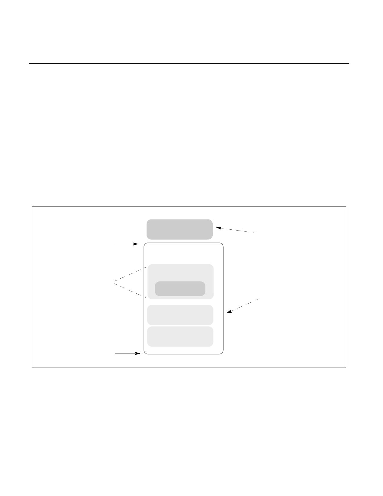
ENCLAVE OPERATION
CHAPTER 39
ENCLAVE OPERATION
The following aspects of enclave operation are described in this chapter:
• Enclave creation: Includes loading code and data from outside of enclave into the EPC and establishing the
enclave entity.
• Adding pages and measuring the enclave.
• Initialization of an enclave: Finalizes the cryptographic log and establishes the enclave identity and sealing
identity.
• Enclave entry and exiting including:
- Controlled entry and exit.
- Asynchronous Enclave Exit (AEX) and resuming execution after an AEX.
39.1
CONSTRUCTING AN ENCLAVE
Figure 39-1 illustrates a typical Enclave memory layout.
SECS
OS Context
Base + Size
Enclave Memory
Thread Data
Replicated once
per thread
TCS
Application Context
Global Data
Code
Base
Enclave {Base, Size}
Figure 39-1. Enclave Memory Layout
The enclave creation, commitment of memory resources, and finalizing the enclave’s identity with measurement
comprises multiple phases. This process can be illustrated by the following exemplary steps:
1. The application hands over the enclave content along with additional information required by the enclave
creation API to the enclave creation service running at privilege level 0.
2. The enclave creation service running at privilege level 0 uses the ECREATE leaf function to set up the initial
environment, specifying base address and size of the enclave. This address range, the ELRANGE, is part of the
application's address space. This reserves the memory range. The enclave will now reside in this address
Vol. 3D
39-1
ENCLAVE OPERATION
region. ECREATE also allocates an Enclave Page Cache (EPC) page for the SGX Enclave Control Structure
(SECS). Note that this page is not required to be a part of the enclave linear address space and is not required
to be mapped into the process.
3. The enclave creation service uses the EADD leaf function to commit EPC pages to the enclave, and use
EEXTEND to measure the committed memory content of the enclave. For each page to be added to the enclave:
- Use EADD to add the new page to the enclave.
- If the enclave developer requires measurement of the page as a proof for the content, use EEXTEND to add
a measurement for 256 bytes of the page. Repeat this operation until the entire page is measured.
4. The enclave creation service uses the EINIT leaf function to complete the enclave creation process and finalize
the enclave measurement to establish the enclave identity. Until an EINIT is executed, the enclave is not
permitted to execute any enclave code (i.e., entering the enclave by executing EENTER would result in a fault).
39.1.1 ECREATE
The ECREATE leaf function sets up the initial environment for the enclave by reading an SGX Enclave Control Struc-
ture (SECS) that contains the enclave's address range (ELRANGE) as defined by BASEADDR and SIZE, the ATTRI-
BUTES and MISCSELECT bitmaps, and the SSAFRAMESIZE. It then securely stores this information in an Enclave
Page Cache (EPC) page. ELRANGE is part of the application's address space. ECREATE also initializes a cryp-
tographic log of the enclave's build process.
39.1.2 EADD and EEXTEND Interaction
Once the SECS has been created, enclave pages can be added to the enclave via EADD. This involves converting a
free EPC page into either a PT_REG or a PT_TCS page.
When EADD is invoked, the processor will update the EPCM entry with the type of page (PT_REG or PT_TCS), the
linear address used by the enclave to access the page, and the enclave access permissions for the page. It associ-
ates the page to the SECS provided as input. The EPCM entry information is used by hardware to manage access
control to the page. EADD records EPCM information in the cryptographic log stored in the SECS and copies 4
KBytes of data from unprotected memory outside the EPC to the allocated EPC page.
System software is responsible for selecting a free EPC page. System software is also responsible for providing the
type of page to be added, the attributes of the page, the contents of the page, and the SECS (enclave) to which the
page is to be added as requested by the application. Incorrect data would lead to a failure of EADD or to an incor-
rect cryptographic log and a failure at EINIT time.
After a page has been added to an enclave, software can measure a 256 byte region as determined by the devel-
oper by invoking EEXTEND. Thus to measure an entire 4KB page, system software must execute EEXTEND 16
times. Each invocation of EEXTEND adds to the cryptographic log information about which region is being measured
and the measurement of the section.
Entries in the cryptographic log define the measurement of the enclave and are critical in gaining assurance that
the enclave was correctly constructed by the untrusted system software.
39.1.3 EINIT Interaction
Once system software has completed the process of adding and measuring pages, the enclave needs to be initial-
ized by the EINIT leaf function. After an enclave is initialized, EADD and EEXTEND are disabled for that enclave (An
attempt to execute EADD/EEXTEND to enclave after enclave initialization will result in a fault). The initialization
process finalizes the cryptographic log and establishes the enclave identity and sealing identity used by
EGETKEY and EREPORT.
A cryptographic hash of the log is stored as the enclave identity. Correct construction of the enclave results in the
cryptographic hash matching the one built by the enclave owner and included as the ENCLAVEHASH field of
SIGSTRUCT. The enclave identity provided by the EREPORT leaf function can be verified by a remote party.
39-2
Vol. 3D
ENCLAVE OPERATION
The EINIT leaf function checks the EINIT token to validate that the enclave has been enabled on this platform. If
the enclave is not correctly constructed, or the EINIT token is not valid for the platform, or SIGSTRUCT isn't prop-
erly signed, then EINIT will fail. See the EINIT leaf function for details on the error reporting.
The enclave identity is a cryptographic hash that reflects the enclave attributes and MISCSELECT value, content
of the enclave, the order in which it was built, the addresses it occupies in memory, the security attributes, and
access right permissions of each page. The enclave identity is established by the EINIT leaf function.
The sealing identity is managed by a sealing authority represented by the hash of the public key used to sign the
SIGSTRUCT structure processed by EINIT. The sealing authority assigns a product ID (ISVPRODID) and security
version number (ISVSVN) to a particular enclave identity.
EINIT establishes the sealing identity using the following steps:
1. Verifies that SIGSTRUCT is properly signed using the public key enclosed in the SIGSTRUCT.
2. Checks that the measurement of the enclave matches the measurement of the enclave specified in SIGSTRUCT.
3. Checks that the enclave’s attributes and MISCSELECT values are compatible with those specified in SIGSTRUCT.
4. Finalizes the measurement of the enclave and records the sealing identity (the sealing authority, product id
and security version number) and enclave identity in the SECS.
5. Sets the ATTRIBUTES.INIT bit for the enclave.
39.1.4 Intel® SGX Launch Control Configuration
Intel® SGX Launch Control is a set of controls that govern the creation of enclaves. Before the EINIT leaf function
will successfully initialize an enclave, a designated Launch Enclave must create an EINITTOKEN for that enclave.
Launch Enclaves have SECS.ATTRIBUTES.EINITTOKEN_KEY = 1, granting them access to the EINITTOKEN_KEY
from the EGETKEY leaf function. EINITTOKEN_KEY must be used by the Launch Enclave when computing EINIT-
TOKEN.MAC, the Message Authentication Code of the EINITTOKEN.
The hash of the public key used to sign the SIGSTRUCT of the Launch Enclave must equal the value in the IA32_S-
GXLEPUBKEYHASH MSRs. Only Launch Enclaves are allowed to launch without a valid token.
The IA32_SGXLEPUBKEYHASH MSRs are provided to designate the platform’s Launch Enclave. IA32_SGXLEPUB-
KEYHASH defaults to digest of Intel’s launch enclave signing key after reset.
IA32_FEATURE_CONTROL bit 17 controls the permissions on the IA32_SGXLEPUBKEYHASH MSRs when
CPUID.12H.00H:EAX[0] = 1. If IA32_FEATURE_CONTROL is locked with bit 17 set, IA32_SGXLEPUBKEYHASH
MSRs are reconfigurable (writeable). If either IA32_FEATURE_CONTROL is not locked or bit 17 is clear, the MSRs
are read only. By leaving these MSRs writable, system SW or a VMM can support a plurality of Launch Enclaves for
hosting multiple execution environments. See Table 43.2.2 for more details.
39.2
ENCLAVE ENTRY AND EXITING
39.2.1 Controlled Entry and Exit
The EENTER leaf function is the method to enter the enclave under program control. To execute EENTER, software
must supply an address of a TCS that is part of the enclave to be entered. The TCS holds the location inside the
enclave to transfer control to and a pointer to the SSA frame inside the enclave that an AEX should store the
register state to.
When a logical processor enters an enclave, the TCS is considered busy until the logical processors exits the
enclave. An attempt to enter an enclave through a busy TCS results in a fault. Intel® SGX allows an enclave builder
to define multiple TCSs, thereby providing support for multithreaded enclaves.
Software must also supply to EENTER the Asynchronous Exit Pointer (AEP) parameter. AEP is an address external
to the enclave which an exception handler will return to using IRET. Typically the location would contain the
ERESUME instruction. ERESUME transfers control back to the enclave, to the address retrieved from the enclave
thread’s saved state.
EENTER performs the following operations:
Vol. 3D
39-3
ENCLAVE OPERATION
1. Check that TCS is not busy and flush all cached linear-to-physical mappings.
2. Change the mode of operation to be in enclave mode.
3. Save the old RSP, RBP for later restore on AEX (Software is responsible for setting up the new RSP, RBP to be
used inside enclave).
4. Save XCR0 and replace it with the XFRM value for the enclave.
5. Check if software wishes to debug (applicable to a debuggable enclave):
- If not debugging, then configure hardware so the enclave appears as a single instruction.
- If debugging, then configure hardware to allow traps, breakpoints, and single steps inside the enclave.
6. Set the TCS as busy.
7. Transfer control from outside enclave to predetermined location inside the enclave specified by the TCS.
The EEXIT leaf function is the method of leaving the enclave under program control. EEXIT receives the target
address outside of the enclave that the enclave wishes to transfer control to. It is the responsibility of enclave soft-
ware to erase any secret from the registers prior to invoking EEXIT. To allow enclave software to easily perform an
external function call and re-enter the enclave (using EEXIT and EENTER leaf functions), EEXIT returns the value of
the AEP that was used when the enclave was entered.
EEXIT performs the following operations:
1. Clear enclave mode and flush all cached linear-to-physical mappings.
2. Mark TCS as not busy.
3. Transfer control from inside the enclave to a location on the outside specified as parameter to the EEXIT leaf
function.
39.2.2 Asynchronous Enclave Exit (AEX)
Asynchronous and synchronous events, such as exceptions, interrupts, traps, SMIs, and VM exits may occur while
executing inside an enclave. These events are referred to as Enclave Exiting Events (EEE). Upon an EEE, the
processor state is securely saved inside the enclave (in the thread’s current SSA frame) and then replaced by a
synthetic state to prevent leakage of secrets. The process of securely saving state and establishing the synthetic
state is called an Asynchronous Enclave Exit (AEX). Details of AEX is described in Chapter 40, “Enclave Exiting
Events.”
As part of most EEEs, the AEP is pushed onto the stack as the location of the eventing address. This is the location
where control will return to after executing the IRET. The ERESUME leaf function can be executed from that point
to reenter the enclave and resume execution from the interrupted point.
After AEX has completed, the logical processor is no longer in enclave mode and the exiting event is processed
normally. Any new events that occur after the AEX has completed are treated as having occurred outside the
enclave (e.g., a #PF in dispatching to an interrupt handler).
39.2.3 Resuming Execution After AEX
After system software has serviced the event that caused the logical processor to exit an enclave, the logical
processor can continue enclave execution using ERESUME. ERESUME restores processor state and returns control
to where execution was interrupted.
If the cause of the exit was an exception or a fault and was not resolved, the event will be triggered again if the
enclave is re-entered using ERESUME. For example, if an enclave performs a divide by 0 operation, executing
ERESUME will cause the enclave to attempt to re-execute the faulting instruction and result in another divide by 0
exception. Intel® SGX provides the means for an enclave developer to handle enclave exceptions from within the
enclave. Software can enter the enclave at a different location and invoke the exception handler within the enclave
by executing the EENTER leaf function. The exception handler within the enclave can read the fault information
from the SSA frame and attempt to resolve the faulting condition or simply return and indicate to software that the
enclave should be terminated (e.g., using EEXIT).
39-4
Vol. 3D
ENCLAVE OPERATION
39.2.3.1 ERESUME Interaction
ERESUME restores registers depending on the mode of the enclave (32 or 64 bit).
• In 32-bit mode (IA32_EFER.LMA = 0 || CS.L = 0), the low 32-bits of the legacy registers (EAX, EBX, ECX, EDX,
ESP, EBP, ESI, EDI, EIP, and EFLAGS) are restored from the thread’s GPR area of the current SSA frame. Neither
the upper 32 bits of the legacy registers nor the 64-bit registers (R8 … R15) are loaded.
• In 64-bit mode (IA32_EFER.LMA = 1 && CS.L = 1), all 64 bits of the general processor registers (RAX, RBX,
RCX, RDX, RSP, RBP, RSI, RDI, R8 … R15, RIP, and RFLAGS) are loaded.
Extended features specified by SECS.ATTRIBUTES.XFRM are restored from the XSAVE area of the current SSA
frame. The layout of the x87 area depends on the current values of IA32_EFER.LMA and CS.L:
• IA32_EFER.LMA = 0 || CS.L = 0
- 32-bit load in the same format that XSAVE/FXSAVE uses with these values.
• IA32_EFER.LMA = 1 && CS.L = 1
- 64-bit load in the same format that XSAVE/FXSAVE uses with these values as if REX.W = 1.
39.2.3.2 Asynchronous Enclave Exit Notify and EDECCSSA
Asynchronous Enclave Exit Notify (AEX-Notify) is an extension to Intel SGX that allows Intel SGX enclaves to be
notified after an asynchronous enclave exit (AEX) has occurred. EDECCSSA is a new Intel SGX user leaf function
(ENCLU[EDECCSSA]) that can facilitate AEX notification handling, as well as software exception handling. This
section provides information about changes to the Intel SGX architecture that support AEX-Notify and
ENCLU[EDECCSSA].
NOTE
On some platforms, AEX-Notify and the EDECCSSA user leaf function may be enumerated by
CPUID following a microcode update.
The following list summarizes the additions to existing Intel SGX data structures to support AEX-Notify:
• SECS.ATTRIBUTES.AEXNOTIFY: This enclave supports AEX-Notify.
• TCS.FLAGS.AEXNOTIFY: This enclave thread may receive AEX notifications.
• SSA.GPRSGX.AEXNOTIFY: Enclave-writable byte that allows enclave software to dynamically enable/disable
AEX notifications.
An AEX notification is delivered by ENCLU[ERESUME] when the following conditions are met:
1. TCS.FLAGS.AEXNOTIFY is set.
2. TCS.CSSA (the current slot index of an SSA frame) is greater than zero.
3. TCS.SSA[TCS.CSSA-1].GPRSGX.AEXNOTIFY[0] is set.
Note that AEX increments TCS.CSSA, and ENCLU[ERESUME] decrements TCS.CSSA, except when an AEX notifica-
tion is delivered. Instead of decrementing TCS.CSSA and restoring state from the SSA, ENCLU[ERESUME] delivers
an AEX notification by behaving as ENCLU[EENTER]. Implications of this behavior include:
• The enclave thread is resumed at EnclaveBase + TCS.OENTRY.
• EAX contains the (non-decremented) value of TCS.CSSA.
• RCX contains the address of the IP following ENCLU[ERESUME].
• The architectural state saved by the most recent AEX is preserved in TCS.SSA[TCS.CSSA-1].
The enclave thread can return to the previous SSA context by invoking ENCLU[EDECCSSA], which decrements
TCS.CSSA.
Vol. 3D
39-5
ENCLAVE OPERATION
39.3
CALLING ENCLAVE PROCEDURES
39.3.1 Calling Convention
In standard call conventions subroutine parameters are generally pushed onto the stack. The called routine, being
aware of its own stack layout, knows how to find parameters based on compile-time-computable offsets from the
SP or BP register (depending on runtime conventions used by the compiler).
Because of the stack switch when calling an enclave, stack-located parameters cannot be found in this manner.
Entering the enclave requires a modified parameter passing convention.
For example, the caller might push parameters onto the untrusted stack and then pass a pointer to those parame-
ters in RAX to the enclave software. The exact choice of calling conventions is up to the writer of the edge routines;
be those routines hand-coded or compiler generated.
39.3.2 Register Preservation
As with most systems, it is the responsibility of the callee to preserve all registers except that used for returning a
value. This is consistent with conventional usage and tends to optimize the number of register save/restore opera-
tions that need be performed. It has the additional security result that it ensures that data is scrubbed from any
registers that were used by enclave to temporarily contain secrets.
39.3.3 Returning to Caller
No registers are modified during EEXIT. It is the responsibility of software to remove secrets in registers before
executing EEXIT.
39.4
INTEL® SGX KEY AND ATTESTATION
39.4.1 Enclave Measurement and Identification
During the enclave build process, two “measurements” are taken of each enclave and are stored in two 256-bit
Measurement Registers (MR): MRENCLAVE and MRSIGNER. MRENCLAVE represents the enclave's contents and
build process. MRSIGNER represents the entity that signed the enclave's SIGSTRUCT.
The values of the Measurement Registers are included in attestations to identify the enclave to remote parties. The
MRs are also included in most keys, binding keys to enclaves with specific MRs.
39.4.1.1 MRENCLAVE
MRENCLAVE is a unique 256 bit value that identifies the code and data that was loaded into the enclave during the
initial launch. It is computed as a SHA256 hash that is initialized by the ECREATE leaf function. EADD and EEXTEND
leaf functions record information about each page and the content of those pages. The EINIT leaf function finalizes
the hash, which is stored in SECS.MRENCLAVE. Any tampering with the build process, contents of a page, page
permissions, etc will result in a different MRENCLAVE value.
Figure 39-2 illustrates a simplified flow of changes to the MRENCLAVE register when building an enclave:
• Enclave creation with ECREATE.
• Copying a non-enclave source page into the EPC of an un-initialized enclave with EADD.
• Updating twice of the MRENCLAVE after modifying the enclave’s page content, i.e., EEXTEND twice.
• Finalizing the enclave build with EINIT.
Details on specific values inserted in the hash are available in the individual instruction definitions.
39-6
Vol. 3D
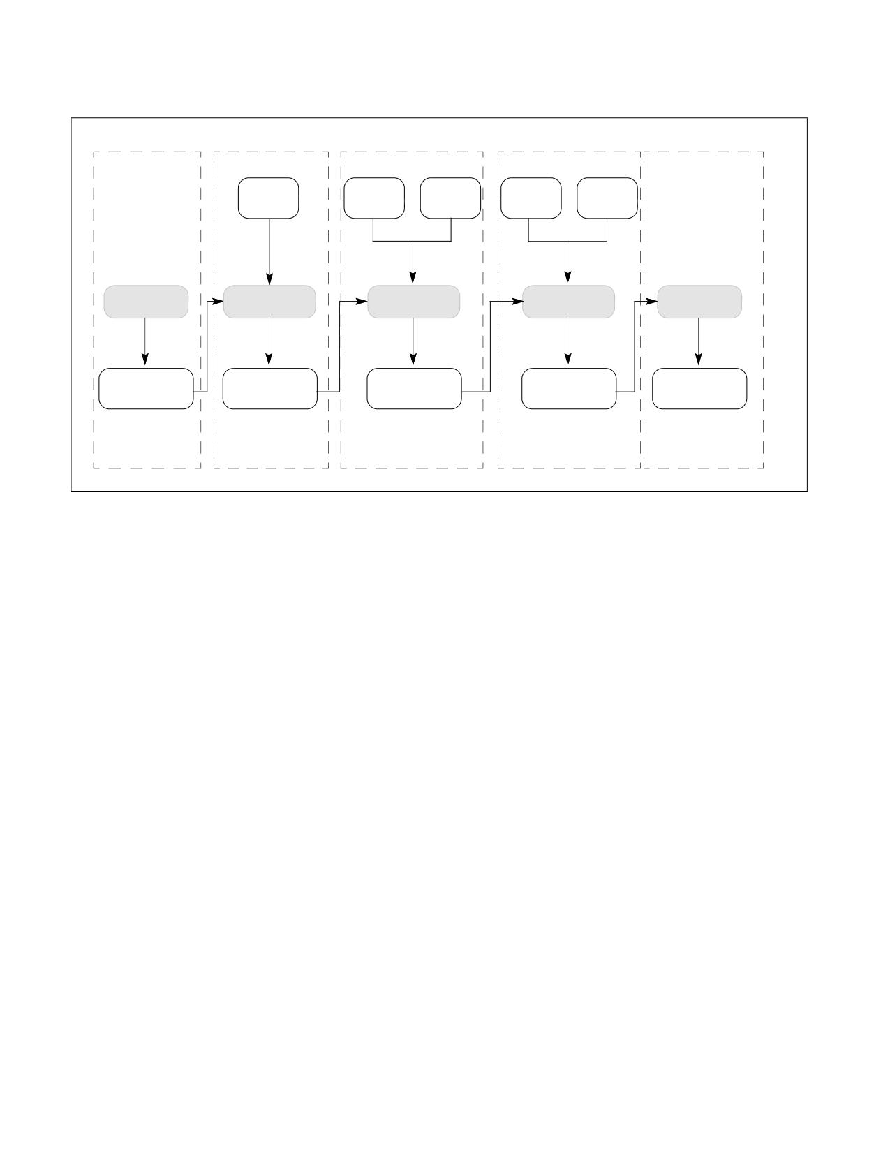
ENCLAVE OPERATION
Page
Data
Chunk 1
Data
Chunk 2
Metadata
Chunk 1
Metadata
Chunk 2
Metadata
SHA_INIT
SHA_UPDATE
SHA_UPDATE
SHA_UPDATE
SHA_FINAL
MRENCLAVE
MRENCLAVE
MRENCLAVE
MRENCLAVE
MRENCLAVE
ECREATE
EADD
EEXTEND
EEXTEND
EINIT
Figure 39-2. Measurement Flow of Enclave Build Process
39.4.1.2 MRSIGNER
Each enclave is signed using a 3072 bit RSA key. The signature is stored in the SIGSTRUCT. In the SIGSTRUCT, the
enclave's signer also assigns a product ID (ISVPRODID) and a security version (ISVSVN) to the enclave.
MRSIGNER is the SHA-256 hash of the signer's public key. For platforms that support Key Separation and Sharing
(CPUID.12H.01H:EAX.KSS[7]) the SIGSTRUCT can additionally specify an 16 byte extended product ID (ISVEXT-
PRODID), and a 16 byte family ID (ISVFAMILYID).
In attestation, MRSIGNER can be used to allow software to approve of an enclave based on the author rather than
maintaining a list of MRENCLAVEs. It is used in key derivation to allow software to create a lineage of an applica-
tion. By signing multiple enclaves with the same key, the enclaves will share the same keys and data. Combined
with security version numbering, the author can release multiple versions of an application which can access keys
for previous versions, but not future versions of that application.
39.4.1.3 CONFIGID
For platforms that support enhancements for key separation and sharing (CPUID.12H.01H:EAX.KSS[7]) when the
enclave is created the platform can additionally provide 32-byte configuration identifier (CONFIGID). How this
value is used is dependent on the enclave but it is intended to allow enclave creators to indicate what additional
content may be accepted by the enclave post-initialization.
39.4.2 Security Version Numbers (SVN)
Intel® SGX supports a versioning system that allows the signer to identify different versions of the same software
released by an author. The security version is independent of the functional version an author uses and is intended
to specify security equivalence. Multiple releases with functional enhancements may all share the same SVN if they
all have the same security properties or posture. Each enclave has an SVN and the underlying hardware has an
SVN.
The SVNs are attested to in EREPORT and are included in the derivation of most keys, thus providing separation
between data for older/newer versions.
Vol. 3D
39-7
ENCLAVE OPERATION
39.4.2.1 Enclave Security Version
In the SIGSTRUCT, the MRSIGNER is associated with a 16-bit Product ID (ISVPRODID) and a 16 bit integer SVN
(ISVSVN). Together they define a specific group of versions of a specific product. Most keys, including the Seal Key,
can be bound to this pair.
To support upgrading from one release to another, EGETKEY will return keys corresponding to any value less than
or equal to the software's ISVSVN.
39.4.2.2 Hardware Security Version
CPUSVN is a 128 bit value that reflects the microcode update version and authenticated code modules supported
by the processor. Unlike ISVSVN, CPUSVN is not an integer and cannot be compared mathematically. Not all values
are valid CPUSVNs.
Software must ensure that the CPUSVN provided to EGETKEY is valid. EREPORT will return the CPUSVN of the
current environment. Software can execute EREPORT with TARGETINFO set to zeros to retrieve a CPUSVN from
REPORTDATA. Software can access keys for a CPUSVN recorded previously, provided that each of the elements
reflected in CPUSVN are the same or have been upgraded.
39.4.2.3 CONFIGID Security Version
The CONFIGID field can be used to contain the hash of a signing key for verifying the additional content. In this
case, similar to the relationship between MRSIGNER and ISVSVN, CONFIGID needs a CONFIGID Security Version
Number. CONFIGIDSVN can be specified at the same time as CONFIGID.
39.4.3 Keys
Intel® SGX provides software with access to keys unique to each processor and rooted in HW keys inserted into the
processor during manufacturing.
Each enclave requests keys using the EGETKEY leaf function. The key is based on enclave parameters such as
measurement, the enclave signing key, security attributes of the enclave, and the Hardware Security version of the
processor itself. A full list of parameter options is specified in the KEYREQUEST structure, see details in Section
38.18.
By deriving keys using enclave properties, SGX guarantees that if two enclaves call EGETKEY, they will receive a
unique key only accessible by the respective enclave. It also guarantees that the enclave will receive the same key
on every future execution of EGETKEY. Some parameters are optional or configurable by software. For example, a
Seal key can be based on the signer of the enclave, resulting in a key available to multiple enclaves signed by the
same party.
The EGETKEY leaf function provides several key types. Each key is specific to the processor, CPUSVN, and the
enclave that executed EGETKEY. The EGETKEY instruction definition details how each of these keys is derived, see
Table 41-62. Additionally,
• SEAL Key: The Seal key is a general purpose key for the enclave to use to protect secrets. Typical uses of the
Seal key are encrypting and calculating MAC of secrets on disk. There are 2 types of Seal Key described in
Section 39.4.3.1.
• REPORT Key: This key is used to compute the MAC on the REPORT structure. The EREPORT leaf function is used
to compute this MAC, and destination enclave uses the Report key to verify the MAC. The software usage flow
is detailed in Section 39.4.3.2.
• EINITTOKEN_KEY: This key is used by Launch Enclaves to compute the MAC on EINITTOKENs. These tokens are
then verified in the EINIT leaf function. The key is only available to enclaves with ATTRIBUTE.EINITTOKEN_KEY set
to 1.
• PROVISIONING Key and PROVISIONING SEAL Key: These keys are used by attestation key provisioning
software to prove to remote parties that the processor is genuine and identify the currently executing TCB.
These keys are only available to enclaves with ATTRIBUTE.PROVISIONKEY set to 1.
39-8
Vol. 3D
ENCLAVE OPERATION
39.4.3.1 Sealing Enclave Data
Enclaves can protect persistent data using Seal keys to provide encryption and/or integrity protection. EGETKEY
provides two types of Seal keys specified in KEYREQUEST.KEYPOLICY field: MRENCLAVE-based key and
MRSIGNER-based key.
The MRENCLAVE-based keys are available only to enclave instances sharing the same MRENCLAVE. If a new
version of the enclave is released, the Seal keys will be different. Retrieving previous data requires additional soft-
ware support.
The MRSIGNER-based keys are bound to the 3 tuple (MRSIGNER, ISVPRODID, ISVSVN). These keys are available
to any enclave with the same MRSIGNER and ISVPRODID and an ISVSVN equal to or greater than the key in ques-
tions. This is valuable for allowing new versions of the same software to retrieve keys created before an upgrade.
For platforms that support enhancements for key separation and sharing (CPUID.12H.01H:EAX.KSS[7]) four addi-
tional key policies for seal key derivation are provided. These add the ISVEXTPRODID, ISVFAMILYID, and
CONFIGID/CONFIGSVN to the key derivation. Additionally, there is a policy to remove ISVPRODID from a key deri-
vation to create a shared between different products that share the same MRSIGNER.
39.4.3.2 Using REPORTs for Local Attestation
Intel SGX provides a means for enclaves to securely identify one another, this is referred to as “Local Attestation”.
SGX provides a hardware assertion, REPORT that contains calling enclaves Attributes, Measurements and User
supplied data (described in detail in Section 38.16). Figure 39-3 shows the basic flow of information.
1. The source enclave determines the identity of the target enclave to populate TARGETINFO.
2. The source enclave calls EREPORT instruction to generate a REPORT structure. The EREPORT instruction
conducts the following:
- Populates the REPORT with identify information about the calling enclave.
- Derives the Report Key that is returned when the target enclave executes the EGETKEY. TARGETINFO
provides information about the target.
- Computes a MAC over the REPORT using derived target enclave Report Key.
3. Non-enclave software copies the REPORT from source to destination.
4. The target enclave executes the EGETKEY instruction to request its REPORT key, which is the same key used by
EREPORT at the source.
5. The target enclave verifies the MAC and can then inspect the REPORT to identify the source.
Source Enclave
TARGETINFO
EREPORT
Destination Enclave
(Symmetric Key)
EGETKEY
REPORT KEY
REPORT
Legend:
Verify REPORT
(Symmetric Key)
Hardware
Software
Figure 39-3. SGX Local Attestation
Vol. 3D
39-9
ENCLAVE OPERATION
39.5
EPC AND MANAGEMENT OF EPC PAGES
EPC layout is implementation specific, and is enumerated through CPUID. EPC is typically configured by BIOS at
system boot time.
39.5.1 EPC Implementation
EPC must be properly protected against attacks. One example of EPC implementation could use a Memory Encryp-
tion Engine (MEE). An MEE provides a cost-effective mechanism of creating cryptographically protected volatile
storage using platform DRAM. These units provide integrity, replay, and confidentiality protection. Details are
implementation specific.
39.5.2 OS Management of EPC Pages
The EPC is a finite resource. SGX1 (i.e., CPUID.12H.00H:EAX.SGX1 = 1 but CPUID.12H.00H:EAX.SGX2 = 0)
provides the EPC manager with leaf functions to manage this resource and properly swap pages out of and into the
EPC. For that, the EPC manager would need to keep track of all EPC entries, type and state, context affiliation, and
SECS affiliation.
Enclave pages that are candidates for eviction should be moved to BLOCKED state using EBLOCK instruction that
ensures no new cached virtual to physical address mappings can be created by attempts to reference a BLOCKED
page.
Before evicting blocked pages, EPC manager should execute ETRACK leaf function on that enclave and ensure that
there are no stale cached virtual to physical address mappings for the blocked pages remain on any thread on the
platform.
After removing all stale translations from blocked pages, system software should use the EWB leaf function for
securely evicting pages out of the EPC. EWB encrypts a page in the EPC, writes it to unprotected memory, and
invalidates the copy in EPC. In addition, EWB also creates a cryptographic MAC (PCMD.MAC) of the page and stores
it in unprotected memory. A page can be reloaded back to the processor only if the data and MAC match. To ensure
that only the latest version of the evicted page can be loaded back, the version of the evicted page is stored
securely in a Version Array (VA) in EPC.
SGX1 includes two instructions for reloading pages that have been evicted by system software: ELDU and ELDB.
The difference between the two instructions is the value of the paging state at the end of the instruction. ELDU
results in a page being reloaded and set to an UNBLOCKED state, while ELDB results in a page loaded to a BLOCKED
state.
ELDB is intended for use by a Virtual Machine Monitor (VMM). When a VMM reloads an evicted page, it needs to
restore it to the correct state of the page (BLOCKED vs. UNBLOCKED) as it existed at the time the page was
evicted. Based on the state of the page at eviction, the VMM chooses either ELDB or ELDU.
39.5.2.1 Enhancement to Managing EPC Pages
On processors supporting SGX2 (i.e., CPUID.12H.00H:EAX.SGX2 = 1), the EPC manager can manage EPC
resources (while enclave is running) with more flexibility provided by the SGX2 leaf functions. The additional flexi-
bility is described in Section 39.5.7 through Section 39.5.11.
39.5.3 Eviction of Enclave Pages
Intel SGX paging is optimized to allow the Operating System (OS) to evict multiple pages out of the EPC under a
single synchronization.
The suggested flow for evicting a list of pages from the EPC is:
1. For each page to be evicted from the EPC:
a. Select an empty slot in a Version Array (VA) page.
• If no empty VA page slots exist, create a new VA page using the EPA leaf function.
39-10
Vol. 3D
ENCLAVE OPERATION
b. Remove linear-address to physical-address mapping from the enclave context’s mapping tables (page table
and EPT tables).
c. Execute the EBLOCK leaf function for the target page. This sets the target page state to BLOCKED. At this
point no new mappings of the page will be created. So any access which does not have the mapping cached
in the TLB will generate a #PF.
2. For each enclave containing pages selected in step 1:
- Execute an ETRACK leaf function pointing to that enclave’s SECS. This initiates the tracking process that
ensures that all caching of linear-address to physical-address translations for the blocked pages is cleared.
3. For all logical processors executing in processes (OS) or guests (VMM) that contain the enclaves selected in
step 1:
- Issue an IPI (inter-processor interrupt) to those threads. This causes those logical processors to asynchro-
nously exit any enclaves they might be in, and as a result flush cached linear-address to physical-address
translations that might hold stale translations to blocked pages. There is no need for additional measures
such as performing a “TLB shootdown”.
4. After enclaves exit, allow logical processors to resume normal operation, including enclave re-entry as the
tracking logic keeps track of the activity.
5. For each page to be evicted:
- Evict the page using the EWB leaf function with parameters include the effective-address pointer to the EPC
page, the VA slot, a 4K byte buffer to hold the encrypted page contents, and a 128 byte buffer to hold page
metadata. The last three elements are tied together cryptographically and must be used to later reload the
page.
At this point, system software has the only copy of each page data encrypted with its page metadata in main
memory.
39.5.4 Loading an Enclave Page
To reload a previously evicted page, system software needs four elements: the VA slot used when the page was
evicted, a buffer containing the encrypted page contents, a buffer containing the page metadata, and the parent
SECS to associate this page with. If the VA page or the parent SECS are not already in the EPC, they must be
reloaded first.
1. Execute ELDB/ELDU (depending on the desired BLOCKED state for the page), passing as parameters: the EPC
page linear address, the VA slot, the encrypted page, and the page metadata.
2. Create a mapping in the enclave context’s mapping tables (page tables and EPT tables) to allow the application
to access that page (OS: system page table; VMM: EPT).
The ELDB/ELDU instruction marks the VA slot empty so that the page cannot be replayed at a later date.
39.5.5 Eviction of an SECS Page
The eviction of an SECS page is similar to the eviction of an enclave page. The only difference is that an SECS page
cannot be evicted until all other pages belonging to the enclave have been evicted. Since all other pages have been
evicted, there will be no threads executing inside the enclave and tracking with ETRACK isn’t necessary. When
reloading an enclave, the SECS page must be reloaded before all other constituent pages.
1. Ensure all pages are evicted from enclave.
2. Select an empty slot in a Version Array page.
- If no VA page exists with an empty slot, create a new one using the EPA function leaf.
3. Evict the page using the EWB leaf function with parameters include the effective-address pointer to the EPC
page, the VA slot, a 4K byte buffer to hold the encrypted page contents and a 128 byte buffer to hold page
metadata. The last three elements are tied together cryptographically and must be used to later reload the
page.
Vol. 3D
39-11
ENCLAVE OPERATION
39.5.6 Eviction of a Version Array Page
VA pages do not belong to any enclave and tracking with ETRACK isn’t necessary. When evicting the VA page, a slot
in a different VA page must be specified in order to provide versioning of the evicted VA page.
1. Select a slot in a Version Array page other than the page being evicted.
- If no VA page exists with an empty slot, create a new one using the EPA leaf function.
2. Evict the page using the EWB leaf function with parameters include the effective-address pointer to the EPC
page, the VA slot, a 4K byte buffer to hold the encrypted page contents, and a 128 byte buffer to hold page
metadata. The last three elements are tied together cryptographically and must be used to later reload the
page.
39.5.7 Allocating a Regular Page
On processors that support SGX2, allocating a new page to an already initialized enclave is accomplished by
invoking the EAUG leaf function. Typically, the enclave requests that the OS allocates a new page at a particular
location within the enclave’s address space. Once allocated, the page remains in a pending state until the enclave
executes the corresponding EACCEPT leaf function to accept the new page into the enclave. Page allocation opera-
tions may be batched to improve efficiency.
The typical process for allocating a regular page is as follows:
1. Enclave requests additional memory from OS when the current allocation becomes insufficient.
2. The OS invokes the EAUG leaf function to add a new memory page to the enclave.
a. EAUG may only be called on a free EPC page.
b. Successful completion of the EAUG instruction places the target page in the VALID and PENDING state.
c. All dynamically created pages have the type PT_REG and content of all zeros.
3. The OS maps the page in the enclave context's mapping tables.
4. The enclave issues an EACCEPT instruction, which verifies the page’s attributes and clears the PENDING state.
At that point the page becomes accessible for normal enclave use.
39.5.8 Allocating a TCS Page
On processors that support SGX2, allocating a new TCS page to an already initialized enclave is a two-step process.
First the OS allocates a regular page with a call to EAUG. This page must then be accepted and initialized by the
enclave to which it belongs. Once the page has been initialized with appropriate values for a TCS page, the enclave
requests the OS to change the page’s type to PT_TCS. This change must also be accepted. As with allocating a
regular page, TCS allocation operations may be batched.
A typical process for allocating a TCS page is as follows:
1. Enclave requests an additional page from the OS.
2. The OS invokes EAUG to add a new regular memory page to the enclave.
a. EAUG may only be called on a free EPC page.
b. Successful completion of the EAUG instruction places the target page in the VALID and PENDING state.
3. The OS maps the page in the enclave context's mapping tables.
4. The enclave issues an EACCEPT instruction, at which point the page becomes accessible for normal enclave use.
5. The enclave initializes the contents of the new page.
6. The enclave requests that the OS convert the page from type PT_REG to PT_TCS.
7. OS issues an EMODT instruction on the page.
a. The parameters to EMODT indicate that the regular page should be converted into a TCS.
39-12
Vol. 3D
ENCLAVE OPERATION
b. EMODT forces all access rights to a page to be removed because TCS pages may not be accessed by
enclave code.
8. The enclave issues an EACCEPT instruction to confirm the requested modification.
39.5.9 Trimming a Page
On processors that support SGX2, Intel SGX supports the trimming of an enclave page as a special case of EMODT.
Trimming allows an enclave to actively participate in the process of removing a page from the enclave (dealloca-
tion) by splitting the process into first removing it from the enclave's access and then removing it from the EPC
using the EREMOVE leaf function. The page type PT_TRIM indicates that a page has been trimmed from the
enclave’s address space and that the page is no longer accessible to enclave software. Modifications to a page in
the PT_TRIM state are not permitted; the page must be removed and then reallocated by the OS before the enclave
may use the page again. Page deallocation operations may be batched to improve efficiency.
The typical process for trimming a page from an enclave is as follows:
1. Enclave signals OS that a particular page is no longer in use.
2. OS invokes the EMODT leaf function on the page, requesting that the page’s type be changed to PT_TRIM.
a. SECS and VA pages cannot be trimmed in this way, so the initial type of the page must be PT_REG or
PT_TCS.
b. EMODT may only be called on valid enclave pages.
3. OS invokes the ETRACK leaf function on the enclave containing the page to track removal the TLB addresses
from all the processors.
4. Issue an IPI (inter-processor interrupt) to flush the stale linear-address to physical-address translations for all
logical processors executing in processes that contain the enclave.
5. Enclave issues an EACCEPT leaf function.
6. The OS may now permanently remove the page from the EPC (by issuing EREMOVE).
39.5.10 Restricting the EPCM Permissions of a Page
On processors that support SGX2, restricting the EPCM permissions associated with an enclave page is accom-
plished using the EMODPR leaf function. This operation requires the cooperation of the OS to flush stale entries to
the page and to update the page-table permissions of the page to match. Permissions restriction operations may
be batched.
The typical process for restricting the permissions of an enclave page is as follows:
1. Enclave requests that the OS to restrict the permissions of an EPC page.
2. OS performs permission restriction, flushing cached linear-address to physical-address translations, and page-
table modifications.
a. Invokes the EMODPR leaf function to restrict permissions (EMODPR may only be called on VALID pages).
b. Invokes the ETRACK leaf function on the enclave containing the page to track removal of the TLB addresses
from all the processor.
c. Issue an IPI (inter-processor interrupt) to flush the stale linear-address to physical-address translations for
all logical processors executing in processes that contain the enclave.
d. Sends IPIs to trigger enclave thread exit and TLB shootdown.
e. OS informs the Enclave that all logical processors should now see the new restricted permissions.
3. Enclave invokes the EACCEPT leaf function.
a. Enclave may access the page throughout the entire process.
b. Successful call to EACCEPT guarantees that no stale cached linear-address to physical-address translations
are present.
Vol. 3D
39-13

ENCLAVE OPERATION
39.5.11 Extending the EPCM Permissions of a Page
On processors that support SGX2, extending the EPCM permissions associated with an enclave page is accom-
plished directly by the enclave using the EMODPE leaf function. After performing the EPCM permission extension,
the enclave requests the OS to update the page table permissions to match the extended permission. Security
wise, permission extension does not require enclave threads to leave the enclave as TLBs with stale references to
the more restrictive permissions will be flushed on demand, but to allow forward progress, an OS needs to be
aware that an application might signal a page fault.
The typical process for extending the permissions of an enclave page is as follows:
1. Enclave invokes EMODPE to extend the EPCM permissions associated with an EPC page (EMODPE may only be
called on VALID pages).
2. Enclave requests that OS update the page tables to match the new EPCM permissions.
3. Enclave code resumes.
a. If cached linear-address to physical-address translations are present to the more restrictive permissions,
the enclave thread will page fault. The SGX2-aware OS will see that the page tables permit the access and
resume the thread, which can now successfully access the page because exiting cleared the TLB.
b. If cached linear-address to physical-address translations are not present, access to the page with the new
permissions will succeed without an enclave exit.
39.6
CHANGES TO INSTRUCTION BEHAVIOR INSIDE AN ENCLAVE
This section covers instructions whose behavior changes when executed in enclave mode.
39.6.1 Illegal Instructions
The instructions listed in Table 39-1 are ring 3 instructions which become illegal when executed inside an enclave.
Executing these instructions inside an enclave will generate an exception.
The first row of Table 39-1 enumerates instructions that may cause a VM exit for VMM emulation. Since a VMM
cannot emulate enclave execution, execution of any of these instructions inside an enclave results in an invalid-
opcode exception (#UD) and no VM exit.
The second row of Table 39-1 enumerates I/O instructions that may cause a fault or a VM exit for emulation. Again,
enclave execution cannot be emulated, so execution of any of these instructions inside an enclave results in #UD.
The third row of Table 39-1 enumerates instructions that load descriptors from the GDT or the LDT or that change
privilege level. The former class is disallowed because enclave software should not depend on the contents of the
descriptor tables and the latter because enclave execution must be entirely with CPL = 3. Again, execution of any
of these instructions inside an enclave results in #UD.
The fourth row of Table 39-1 enumerates instructions that provide access to kernel information from user mode and
can be used to aid kernel exploits from within enclave. Execution of any of these instructions inside an enclave
results in #UD.
Table 39-1. Illegal Instructions Inside an Enclave
Instructions
Result
Comment
CPUID, GETSEC, RDPMC, SGDT, SIDT, SLDT, STR, VMCALL, VMFUNC
#UD
Might cause VM exit.
IN, INS/INSB/INSW/INSD, OUT, OUTS/OUTSB/OUTSW/OUTSD
#UD
I/O fault may not safely recover. May require emulation.
Far call, Far jump, Far Ret, INT n/INTO, IRET, LDS/LES/LFS/LGS/LSS,
#UD
Access segment register could change privilege level.
MOV to DS/ES/SS/FS/GS, POP DS/ES/SS/FS/GS, SYSCALL,
SYSENTER
SMSW
#UD
Might provide access to kernel information.
ENCLU[EENTER], ENCLU[ERESUME]
#GP
Cannot enter an enclave from within an enclave.
39-14
Vol. 3D
ENCLAVE OPERATION
RDTSC and RDTSCP are legal inside an enclave for processors that support SGX2 (subject to the value of
CR4.TSD). For processors which support SGX1 but not SGX2, RDTSC and RDTSCP will cause #UD.
RDTSC and RDTSCP instructions may cause a VM exit when inside an enclave.
Software developers must take into account that the RDTSC/RDTSCP results are not immune to influences by other
software, e.g., the TSC can be manipulated by software outside the enclave.
39.6.2 RDRAND and RDSEED Instructions
These instructions may cause a VM exit if the “RDRAND exiting” VM-execution control is 1. Unlike other instructions
that can cause VM exits, these instructions are legal inside an enclave. As noted in Section 30.1 of the Intel® 64
and IA-32 Architectures Software Developer’s Manual, Volume 3C, any VM exit originating on an instruction
boundary inside an enclave sets bit 27 of the exit-reason field of the VMCS. If a VMM receives a VM exit due to an
attempt to execute either of these instructions determines (by that bit) that the execution was inside an enclave,
it can do either of two things. It can clear the “RDRAND exiting” VM-execution control and execute VMRESUME; this
will result in the enclave executing RDRAND or RDSEED again, and this time a VM exit will not occur. Alternatively,
the VMM might choose to discontinue execution of this virtual machine.
NOTE
It is expected that VMMs that virtualize Intel SGX will not set “RDRAND exiting” to 1.
39.6.3 PAUSE Instruction
The PAUSE instruction may cause a VM exit from an enclave if the “PAUSE exiting” VM-execution control is 1. Unlike
other instructions that can cause VM exits, the PAUSE instruction is legal inside an enclave. If a VMM receives a VM
exit due to the 1-setting of “PAUSE exiting”, it can do either of two things. It can clear the “PAUSE exiting” VM-
execution control and execute VMRESUME; this will result in the enclave executing PAUSE again, but this time a VM
exit will not occur. Alternatively, the VMM might choose to discontinue execution of this virtual machine.
The PAUSE instruction may also cause a VM exit outside of an enclave if the “PAUSE-loop exiting” VM-execution
control is 1, but as the “PAUSE-loop exiting” control is ignored at CPL > 0 (see Section 28.1.3), VM exit from an
enclave due to the 1-setting of “PAUSE-LOOP exiting” will never occur.
NOTE
It is expected that VMMs that virtualize Intel SGX will not set “PAUSE exiting” to 1.
39.6.4 Executions of INT1 and INT3 Inside an Enclave
The INT1 and INT3 instructions are legal inside an enclave, however, their behavior inside an enclave differs from
that outside an enclave. See Section 43.4.1 for details.
39.6.5 INVD Handling when Enclaves Are Enabled
Once processor reserved memory protections are activated (see Section 39.5), any execution of INVD will result in
a #GP(0).
Vol. 3D
39-15
ENCLAVE OPERATION
39-16
Vol. 3D
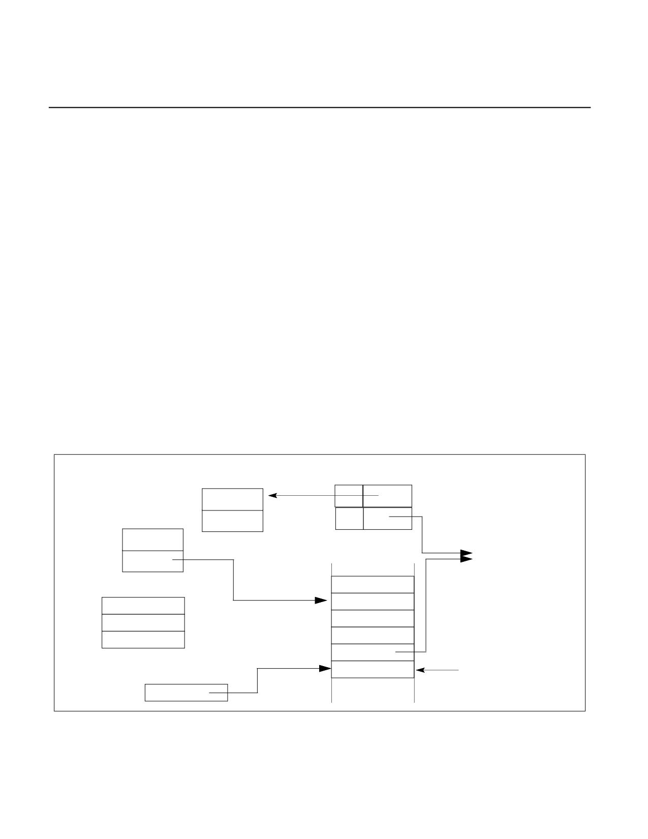
ENCLAVE EXITING EVENTS
CHAPTER 40
ENCLAVE EXITING EVENTS
Certain events, such as exceptions and interrupts, incident to (but asynchronous with) enclave execution may
cause control to transition outside of enclave mode. (Most of these also cause a change of privilege level.) To
protect the integrity and security of the enclave, the processor will exit the enclave (and enclave mode) before
invoking the handler for such an event. For that reason, such events are called enclave-exiting events (EEE);
EEEs include external interrupts, non-maskable interrupts, system-management interrupts, exceptions, and VM
exits.
The process of leaving an enclave in response to an EEE is called an asynchronous enclave exit (AEX). To
protect the secrecy of the enclave, an AEX saves the state of certain registers within enclave memory and then
loads those registers with fixed values called synthetic state.
40.1
COMPATIBLE SWITCH TO THE EXITING STACK OF AEX
AEXs load registers with a pre-determined synthetic state. These registers may be later pushed onto the appro-
priate stack in a form as defined by the enclave-exiting event. To allow enclave execution to resume after the
invoking handler has processed the enclave exiting event, the asynchronous enclave exit loads the address of
trampoline code outside of the enclave into RIP. This trampoline code eventually returns to the enclave by means
of an ENCLU(ERESUME) leaf function. Prior to exiting the enclave the RSP and RBP registers are restored to their
values prior to enclave entry.
The stack to be used is chosen using the same rules as for non-SGX mode:
• If there is a privilege level change, the stack will be the one associated with the new ring.
• If there is no privilege level change, the current application stack is used.
• If the IA-32e IST mechanism is used, the exit stack is chosen using that method.
TCS
Next SSA Frame
CSSA
Current SSA Frame
uRSP
AEP
Per-Thread
Trampoline in uRTS
Exit Stack
uRSP
ENCLU[ERESUME]
SS
RSP
ENCLU[ERESUME]
RAX
RFLAGS
TCS LA
RBX
CS
AEP
RCX
RIP
Error Code (optional)
RSP after pushes
RSP
Figure 40-1. Exit Stack Just After Interrupt with Stack Switch
Vol. 3D
40-1
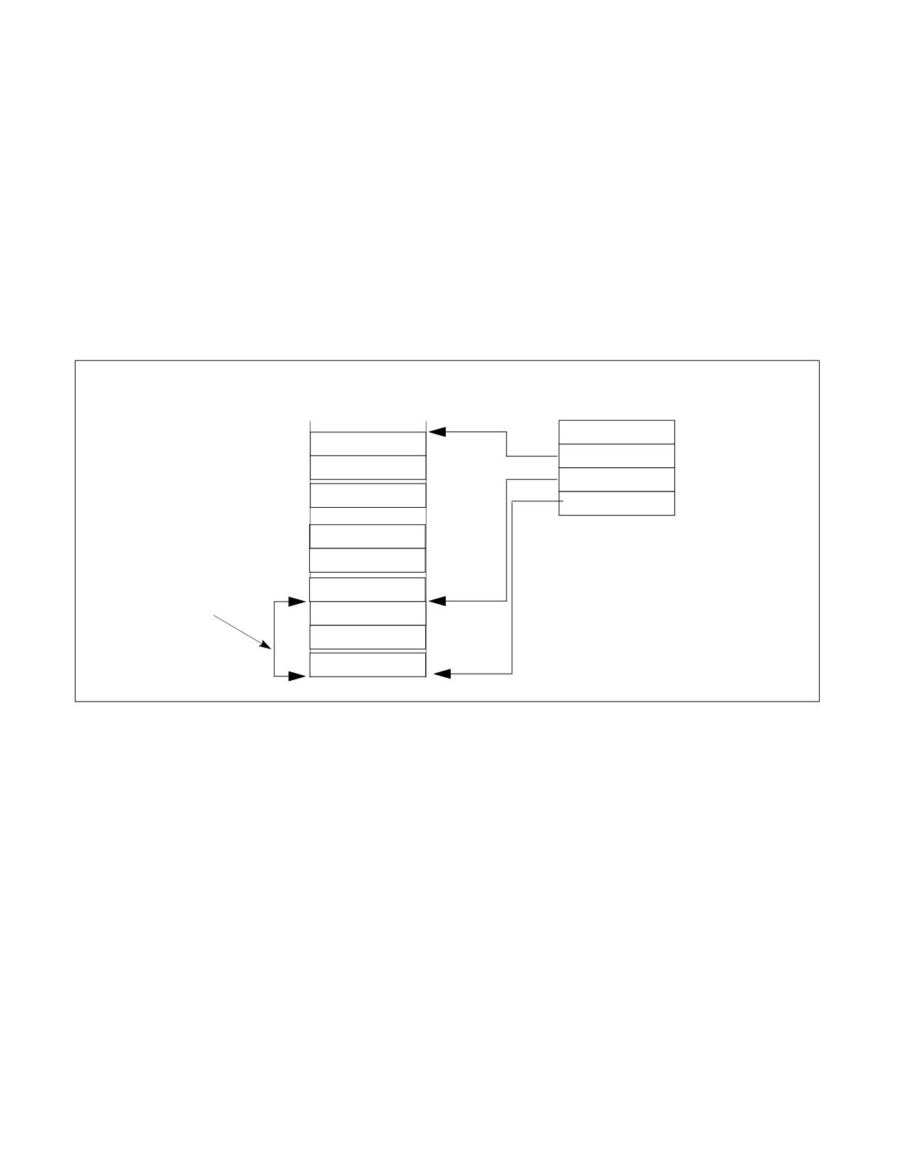
ENCLAVE EXITING EVENTS
In all cases, the choice of exit stack and the information pushed onto it is consistent with non-SGX operation.
Figure 40-1 shows the Application and Exiting Stacks after an exit with a stack switch. An exit without a stack
switch uses the Application Stack. The ERESUME leaf index value is placed into RAX, the TCS pointer is placed in
RBX and the AEP (see below) is placed into RCX to facilitate resuming the enclave after the exit.
Upon an AEX, the AEP (Asynchronous Exit Pointer) is loaded into the RIP. The AEP points to a trampoline code
sequence which includes the ERESUME instruction that is later used to reenter the enclave.
The following bits of RFLAGS are cleared before RFLAGS is pushed onto the exit stack: CF, PF, AF, ZF, SF, OF, RF. The
remaining bits are left unchanged.
40.2
STATE SAVING BY AEX
The State Save Area holds the processor state at the time of an AEX. To allow handling events within the enclave
and re-entering it after an AEX, the SSA can be a stack of multiple SSA frames as illustrated in Figure 40-2.
SSA Stack
TCS
GRP_N-1
NSSA
MISC_N-1
CSSA
XSAVE_N-1
OSSA
GPR_1
MISC_1
Current
SSA Fram
XSAVE_1
SECS.SSAFRAMESIZE
GRP_0
(in pages)
MISC_0
XAVE_0
Figure 40-2. The SSA Stack
The location of the SSA frames to be used is controlled by the following variables in the TCS and the SECS:
• Size of a frame in the State Save Area (SECS.SSAFRAMESIZE): This defines the number of 4-KByte pages in a
single frame in the State Save Area. The SSA frame size must be large enough to hold the GPR state, the XSAVE
state, and the MISC state.
• Base address of the enclave (SECS.BASEADDR): This defines the enclave's base linear address from which the
offset to the base of the SSA stack is calculated.
• Number of State Save Area Slots (TCS.NSSA): This defines the total number of slots (frames) in the State Save
Area stack.
• Current State Save Area Slot (TCS.CSSA): This defines the slot to use on the next exit.
• State Save Area Offset (TCS.OSSA): This defines the offset of the base address of a set of State Save Area slots
from the enclave’s base address.
When an AEX occurs, hardware selects the SSA frame to use by examining TCS.CSSA. Processor state is saved into
the SSA frame (see Section 40.4) and loaded with a synthetic state (as described in Section 40.3.1) to avoid
leaking secrets, RSP and RBP are restored to their values prior to enclave entry, and TCS.CSSA is incremented. As
will be described later, if an exception takes the last slot, it will not be possible to reenter the enclave to handle the
40-2
Vol. 3D

ENCLAVE EXITING EVENTS
exception from within the enclave. A subsequent ERESUME restores the processor state from the current SSA
frame and frees the SSA frame.
The format of the XSAVE section of SSA is identical to the format used by the XSAVE/XRSTOR instructions. On
EENTER, CSSA must be less than NSSA, ensuring that there is at least one State Save Area slot available for exits.
If there is no free SSA frame when executing EENTER, the entry will fail.
40.3
SYNTHETIC STATE ON ASYNCHRONOUS ENCLAVE EXIT
40.3.1 Processor Synthetic State on Asynchronous Enclave Exit
Table 40-1 shows the synthetic state loaded on AEX. The values shown are the lower 32 bits when the processor is
in 32 bit mode and 64 bits when the processor is in 64 bit mode.
Table 40-1. GPR, x87 Synthetic States on Asynchronous Enclave Exit
Register
Value
RAX
3 (ENCLU[3] is ERESUME).
RBX
Pointer to TCS of interrupted enclave thread.
RCX
AEP of interrupted enclave thread.
RDX, RSI, RDI
0.
RSP
Restored from SSA.uRSP.
RBP
Restored from SSA.uRBP.
R8-R15
0 in 64-bit mode; unchanged in 32-bit mode.
RIP
AEP of interrupted enclave thread.
RFLAGS
CF, PF, AF, ZF, SF, OF, RF bits are cleared. All other bits are left unchanged.
x87/SSE State
Unless otherwise listed here, all x87 and SSE state are set to the INIT state. The INIT state is the state
that would be loaded by the XRSTOR instruction with bits 1:0 both set in the requested feature bitmask
(RFBM), and both clear in XSTATE_BV the XSAVE header.
FCW
On #MF exception: set to 037EH. On all other exits: set to 037FH.
FSW
On #MF exception: set to 8081H. On all other exits: set to 0H.
MXCSR
On #XM exception: set to 1F01H. On all other exits: set to 1FB0H.
CR2
If the event that caused the AEX is a #PF, and the #PF does not directly cause a VM exit, then the low
12 bits are cleared.
If the #PF leads directly to a VM exit, CR2 is not updated (usual IA behavior).
Note: The low 12 bits are not cleared if a #PF is encountered during the delivery of the EEE that caused
the AEX. This is because the #PF was not the EEE.
FS, GS
Restored to values as of most recent EENTER/ERESUME.
40.3.2 Synthetic State for Extended Features
When CR4.OSXSAVE = 1, extended features (those controlled by XCR0[63:2]) are set to their respective INIT
states when this corresponding bit of SECS.XFRM is set. The INIT state is the state that would be loaded by the
XRSTOR instruction had the instruction mask and the XSTATE_BV field of the XSAVE header each contained the
value XFRM. (When the AEX occurs in 32-bit mode, those features that do not exist in 32-bit mode are unchanged.)
Vol. 3D
40-3
ENCLAVE EXITING EVENTS
40.3.3 Synthetic State for MISC Features
State represented by SECS.MISCSELECT might also be overridden by synthetic state after it has been saved into
the SSA. State represented by MISCSELECT[0] is not overridden but if the exiting event is a page fault then lower
12 bits of CR2 are cleared.
40.4
AEX FLOW
On Enclave Exiting Events (interrupts, exceptions, VM exits or SMIs), the processor state is securely saved inside
the enclave, a synthetic state is loaded and the enclave is exited. The EEE then proceeds in the usual exit-defined
fashion. The following sections describes the details of an AEX:
1.
The exact processor state saved into the current SSA frame depends on whether the enclave is a 32-bit or a 64-
bit enclave. In 32-bit mode (IA32_EFER.LMA = 0 || CS.L = 0), the low 32 bits of the legacy registers (EAX, EBX,
ECX, EDX, ESP, EBP, ESI, EDI, EIP, and EFLAGS) are stored. The upper 32 bits of the legacy registers and the
64-bit registers (R8 … R15) are not stored.
In 64-bit mode (IA32_EFER.LMA = 1 && CS.L = 1), all 64 bits of the general processor registers (RAX, RBX,
RCX, RDX, RSP, RBP, RSI, RDI, R8 … R15, RIP, and RFLAGS) are stored.
The state of those extended features specified by SECS.ATTRIBUTES.XFRM are stored into the XSAVE area of
the current SSA frame. The layout of the x87 and XMM portions (the 1st 512 bytes) depends on the current
values of IA32_EFER.LMA and CS.L:
If IA32_EFER.LMA = 0 || CS.L = 0, the same format (32-bit) that XSAVE/FXSAVE uses with these values.
If IA32_EFER.LMA = 1 && CS.L = 1, the same format (64-bit) that XSAVE/FXSAVE uses with these values
when REX.W = 1.
The cause of the AEX is saved in the EXITINFO field. See Table 38-10 for details and values of the various
fields.
The state of those miscellaneous features (see Section 38.7.2) specified by SECS.MISCSELECT are stored into
the MISC area of the current SSA frame.
If CET was enabled in the enclave, then the CET state of the enclave is saved in the CET state save area. If
shadow stacks were enabled in the enclave, then the SSP is also saved into the TCS.PREVSSP field.
2.
Synthetic state is created for a number of processor registers to present an opaque view of the enclave state.
Table 40-1 shows the values for GPRs, x87, SSE, FS, GS, Debug, and performance monitoring on AEX. The
synthetic state for other extended features (those controlled by XCR0[62:2]) is set to their respective INIT
states when their corresponding bit of SECS.ATTRIBUTES.XFRM is set. The INIT state is that state as defined by
the behavior of the XRSTOR instruction when HEADER.XSTATE_BV[n] is 0. Synthetic state of those miscella-
neous features specified by SECS.MISCSELECT depends on the miscellaneous feature. There is no synthetic
state required for the miscellaneous state controlled by SECS.MISCSELECT[0].
3.
Any code and data breakpoints that were suppressed at the time of enclave entry are unsuppressed when
exiting the enclave.
4.
RFLAGS.TF is set to the value that it had at the time of the most recent enclave entry (except for the situation
that the entry was opt-in for debug; see Section 43.2). In the SSA, RFLAGS.TF is set to 0.
5.
RFLAGS.RF is set to 0 in the synthetic state. In the SSA, the value saved is the same as what would have been
saved on stack in the non-SGX case (architectural value of RF). Thus, AEXs due to interrupts, traps, and code
breakpoints save RF unmodified into SSA, while AEXs due to other faults save RF as 1 in the SSA.
If the event causing AEX happened on intermediate iteration of a REP-prefixed instruction, then RF=1 is
saved on SSA, irrespective of its priority.
6.
Any performance monitoring activity (including PEBS) or profiling activity (LBR, Tracing using Intel PT) on the
exiting thread that was suppressed due to the enclave entry on that thread is unsuppressed. Any counting that
had been demoted from AnyThread counting to MyThread counting (on one logical processor) is promoted back
to AnyThread counting.
7.
The CET state of the enclosing application is restored to the state at the time of the most recent enclave entry,
and if CET indirect branch tracking was enabled then the indirect branch tracker is unsuppressed and moved to
the WAIT_FOR_ENDBRANCH state.
40-4
Vol. 3D

ENCLAVE EXITING EVENTS
40.4.1 AEX Operational Detail
Temp Variables in AEX Operational Flow
Name
Type
Size (bits)
Description
TMP_RIP
Effective Address
32/64
Address of instruction at which to resume execution on ERESUME.
TMP_MODE64
binary
1
((IA32_EFER.LMA = 1) && (CS.L = 1)).
TMP_BRANCH_RECORD
LBR Record
2x64
From/To address to be pushed onto LBR stack.
The pseudo code in this section describes the internal operations that are executed when an AEX occurs in enclave
mode. These operations occur just before the normal interrupt or exception processing occurs.
(* Save RIP for later use *)
TMP_RIP = Linear Address of Resume RIP
(* Is the processor in 64-bit mode? *)
TMP_MODE64 := ((IA32_EFER.LMA = 1) && (CS.L = 1));
(* Save all registers, When saving EFLAGS, the TF bit is set to 0 and
the RF bit is set to what would have been saved on stack in the non-SGX case *)
IF (TMP_MODE64 = 0)
THEN
Save EAX, EBX, ECX, EDX, ESP, EBP, ESI, EDI, EFLAGS, EIP into the current SSA frame using
CR_GPR_PA; (* see Table 41-4 for list of CREGs used to describe internal operation within Intel SGX *)
SSA.RFLAGS.TF := 0;
ELSE
(* TMP_MODE64 = 1 *)
Save RAX, RBX, RCX, RDX, RSP, RBP, RSI, RDI, R8-R15, RFLAGS, RIP into the current SSA frame using
CR_GPR_PA;
SSA.RFLAGS.TF := 0;
FI;
Save FS and GS BASE into SSA using CR_GPR_PA;
(* store XSAVE state into the current SSA frame's XSAVE area using the physical addresses
that were determined and cached at enclave entry time with CR_XSAVE_PAGE_i. *)
For each XSAVE state i defined by (SECS.ATTRIBUTES.XFRM[i] = 1, destination address cached in
CR_XSAVE_PAGE_i)
SSA.XSAVE.i := XSAVE_STATE_i;
(* Clear bytes 8 to 23 of XSAVE_HEADER, i.e., the next 16 bytes after XHEADER_BV *)
CR_XSAVE_PAGE_0.XHEADER_BV[191:64] := 0;
(* Clear bits in XHEADER_BV[63:0] that are not enabled in ATTRIBUTES.XFRM *)
CR_XSAVE_PAGE_0.XHEADER_BV[63:0] :=
CR_XSAVE_PAGE_0.XHEADER_BV[63:0] & SECS(CR_ACTIVE_SECS).ATTRIBUTES.XFRM;
Apply synthetic state to GPRs, RFLAGS, extended features, etc.
(* Restore the RSP and RBP from the current SSA frame's GPR area using the physical address
that was determined and cached at enclave entry time with CR_GPR_PA. *)
RSP := CR_GPR_PA.URSP;
RBP := CR_GPR_PA.URBP;
AEX Operational Detail
40-5
Vol. 3D
ENCLAVE EXITING EVENTS
(* Restore the FS and GS *)
FS.selector := CR_SAVE_FS.selector;
FS.base := CR_SAVE_FS.base;
FS.limit := CR_SAVE_FS.limit;
FS.access_rights := CR_SAVE_FS.access_rights;
GS.selector := CR_SAVE_GS.selector;
GS.base := CR_SAVE_GS.base;
GS.limit := CR_SAVE_GS.limit;
GS.access_rights := CR_SAVE_GS.access_rights;
(* Examine exception code and update enclave internal states*)
exception_code := Exception or interrupt vector;
(* Indicate the exit reason in SSA *)
IF (exception_code = (#DE OR #DB OR #BP OR #BR OR #UD OR #MF OR #AC OR #XM ))
THEN
CR_GPR_PA.EXITINFO.VECTOR := exception_code;
IF (exception_code = #BP)
THEN CR_GPR_PA.EXITINFO.EXIT_TYPE := 6;
ELSE CR_GPR_PA.EXITINFO.EXIT_TYPE := 3;
FI;
CR_GPR_PA.EXITINFO.VALID := 1;
ELSE IF (SECS.MISCSELECT[0] is set (* Check SECS.MISCSELECT using CR_ACTIVE_SECS *)
AND (exception_code is #GP OR (exception_code is #PF AND PFEC.U/S = 1)))
THEN
CR_GPR_PA.EXITINFO.VECTOR := exception_code;
CR_GPR_PA.EXITINFO.EXIT_TYPE := 3;
IF (exception_code is #PF)
THEN
SSA.MISC.EXINFO. MADDR := CR2;
SSA.MISC.EXINFO.ERRCD := PFEC; (* Page-Fault Exception Error Code *)
SSA.MISC.EXINFO.RESERVED := 0;
ELSE
SSA.MISC.EXINFO. MADDR := 0;
SSA.MISC.EXINFO.ERRCD := GPEC; (* General Protection Exception Error Code *)
SSA.MISC.EXINFO.RESERVED := 0;
FI;
CR_GPR_PA.EXITINFO.VALID := 1;
ELSE IF (SECS.MISCSELECT[1] is set AND exception_code is #CP) (* Check SECS.MISCSELECT using
CR_ACTIVE_SECS *)
THEN
CR_GPR_PA.EXITINFO.VECTOR := exception_code;
CR_GPR_PA.EXITINFO.EXIT_TYPE := 3;
CR_GPR_PA.EXITINFO.VALID := 1;
SSA.MISC.EXINFO. MADDR := 0;
SSA.MISC.EXINFO.ERRCD := CPEC; (* Control Protection Exception Error Code *)
SSA.MISC.EXINFO.RESERVED := 0;
ELSE
SSA.MISC.EXINFO.MADDR := 0;
SSA.MISC.EXINFO.ERRCD := 0;
SSA.MISC.EXINFO.RESERVED := 0;
CR_GPR_PA.EXITINFO.VECTOR := 0;
CR_GPR_PA.EXITINFO.EXIT_TYPE := 0;
40-6
Vol. 3D
AEX Operational Detail
ENCLAVE EXITING EVENTS
CR_GPR_PA.EXITINFO.VALID := 0;
FI;
(* Execution will resume at the AEP *)
RIP := CR_TCS_PA.AEP;
(* Set EAX to the ERESUME leaf index *)
EAX := 3;
(* Put the TCS LA into RBX for later use by ERESUME *)
RBX := CR_TCS_LA;
(* Put the AEP into RCX for later use by ERESUME *)
RCX := CR_TCS_PA.AEP;
(* Increment the SSA frame # *)
CR_TCS_PA.CSSA := CR_TCS_PA.CSSA + 1;
(* Restore XCR0 if needed *)
IF (CR4.OSXSAVE = 1)
THEN XCR0 := CR_SAVE_XCR0; FI;
Un-suppress all code breakpoints that are outside ELRANGE
IF (CPUID.12H.01H:EAX[6]= 1)
THEN
IF (CR4.CET == 1 AND IA32_U_CET.SH_STK_EN == 1)
THEN
CR_CET_SAVE_AREA_PA.SSP := SSP;
CR_TCS_PA.PREVSSP := SSP;
FI;
IF (CR4.CET == 1 AND IA32_U_CET.ENDBR_EN == 1)
THEN
CR_CET_SAVE_AREA_PA.TRACKER := IA32_U_CET.TRACKER;
CR_CET_SAVE_AREA_PA.SUPPRESS := IA32_U_CET.SUPPRESS;
FI;
FI;
IF ((CPUID.07H.00H:EDX.CET_IBT = 1) OR (CPUID.07H.00H:ECX.CET_SS = 1)
THEN
(* restore enclosing applications CET state *)
IA32_U_CET := CR_SAVE_IA32_U_CET;
IF (CPUID.07H.00H:ECX.CET_SS)
SSP := CR_SAVE_SSP; FI;
(* If indirect branch tracking enabled for enclosing application *)
(* then move the tracker to wait_for_endbranch *)
IF (CR4.CET == 1 AND IA32_U_CET.ENDBR_EN == 1)
THEN
IA32_U_CET.TRACKER := WAIT_FOR_ENDBRANCH;
IA32_U_CET.SUPPRESS := 0;
FI;
FI;
AEX Operational Detail
40-7
Vol. 3D
ENCLAVE EXITING EVENTS
(* Update the thread context to show not in enclave mode *)
CR_ENCLAVE_MODE := 0;
(* Assure consistent translations. *)
Flush linear context including TLBs and paging-structure caches
IF (CR_DBGOPTIN = 0)
THEN
Un-suppress all breakpoints that overlap ELRANGE
(* Clear suppressed breakpoint matches *)
Restore suppressed breakpoint matches
(* Restore TF *)
RFLAGS.TF := CR_SAVE_TF;
Un-suppress monitor trap flag;
Un-suppress branch recording facilities;
Un-suppress all suppressed performance monitoring activity;
Promote any sibling-thread counters that were demoted from AnyThread to MyThread during enclave
entry back to AnyThread;
FI;
IF the “monitor trap flag” VM-execution control is 1
THEN Pend MTF VM Exit at the end of exit; FI;
(* Clear low 12 bits of CR2 on #PF *)
IF (Exception code is #PF)
THEN CR2 := CR2 & ~0xFFF; FI;
(* end_of_flow *)
(* Execution continues with normal event processing. *)
40-8
Vol. 3D
AEX Operational Detail

INTEL® SGX INSTRUCTION REFERENCES
CHAPTER 41
INTEL® SGX INSTRUCTION REFERENCES
This chapter describes the supervisor and user level instructions provided by Intel® Software Guard Extensions
(Intel® SGX). In general, various functionality is encoded as leaf functions within the ENCLS (supervisor) and
ENCLU (user) instruction mnemonics. Different leaf functions are encoded by specifying an input value in the EAX
register of the respective instruction mnemonic.
41.1
INTEL® SGX INSTRUCTION SYNTAX AND OPERATION
ENCLS and ENCLU instruction mnemonics for all leaf functions are covered in this section.
For all instructions, the value of CS.D is ignored; addresses and operands are 64 bits in 64-bit mode and are other-
wise 32 bits. Aside from EAX specifying the leaf number as input, each instruction leaf may require all or some
subset of the RBX/RCX/RDX as input parameters. Some leaf functions may return data or status information in one
or more of the general purpose registers.
41.1.1 ENCLS Register Usage Summary
Table 41-1 summarizes the implicit register usage of supervisor mode enclave instructions.
Table 41-1. Register Usage of Privileged Enclave Instruction Leaf Functions
Instr. Leaf
EAX
RBX
RCX
RDX
ECREATE
00H (In)
PAGEINFO (In, EA)
EPCPAGE (In, EA)
EADD
01H (In)
PAGEINFO (In, EA)
EPCPAGE (In, EA)
EINIT
02H (In)
SIGSTRUCT (In, EA)
SECS (In, EA)
EINITTOKEN (In, EA)
EREMOVE
03H (In)
EPCPAGE (In, EA)
EDBGRD
04H (In)
Result Data (Out)
EPCPAGE (In, EA)
EDBGWR
05H (In)
Source Data (In)
EPCPAGE (In, EA)
EEXTEND
06H (In)
SECS (In, EA)
EPCPAGE (In, EA)
ELDB
07H (In)
PAGEINFO (In, EA)
EPCPAGE (In, EA)
VERSION (In, EA)
ELDU
08H (In)
PAGEINFO (In, EA)
EPCPAGE (In, EA)
VERSION (In, EA)
EBLOCK
09H (In)
EPCPAGE (In, EA)
EPA
0AH (In)
PT_VA (In)
EPCPAGE (In, EA)
EWB
0BH (In)
PAGEINFO (In, EA)
EPCPAGE (In, EA)
VERSION (In, EA)
ETRACK
0CH (In)
EPCPAGE (In, EA)
EAUG
0DH (In)
PAGEINFO (In, EA)
EPCPAGE (In, EA)
EMODPR
0EH (In)
SECINFO (In, EA)
EPCPAGE (In, EA)
EMODT
0FH (In)
SECINFO (In, EA)
EPCPAGE (In, EA)
EUPDATESVN
018H (In)
EA: Effective Address
41.1.2 ENCLU Register Usage Summary
Table 41-2 summarizes the implicit register usage of user mode enclave instructions.
Vol. 3D
41-1

INTEL® SGX INSTRUCTION REFERENCES
Table 41-2. Register Usage of Unprivileged Enclave Instruction Leaf Functions
Instr. Leaf
EAX
RBX
RCX
RDX
EREPORT
00H (In)
TARGETINFO (In, EA)
REPORTDATA (In, EA)
OUTPUTDATA (In, EA)
EGETKEY
01H (In)
KEYREQUEST (In, EA)
KEY (In, EA)
EENTER
02H (In)
TCS (In, EA)
AEP (In, EA)
RBX.CSSA (Out)
Return (Out, EA)
ERESUME
03H (In)
TCS (In, EA)
AEP (In, EA)
EEXIT
04H (In)
Target (In, EA)
Current AEP (Out)
EACCEPT
05H (In)
SECINFO (In, EA)
EPCPAGE (In, EA)
EMODPE
06H (In)
SECINFO (In, EA)
EPCPAGE (In, EA)
EACCEPTCOPY
07H (In)
SECINFO (In, EA)
EPCPAGE (In, EA)
EPCPAGE (In, EA)
EVERIFYREPORT2
08H (In)
REPORTMACSTRUCT1 (In, EA)
EDECCSSA
09H (In)
EA: Effective Address
NOTES:
1. More details about REPORTMACSTRUCT can be found in Section “Report MAC Structure (REPORTMAC-
STRUCT)” of the Intel® Architecture Instruction Set Extensions and Future Features Programming Refer-
ence.
41.1.3 Information and Error Codes
Information and error codes are reported by various instruction leaf functions to show an abnormal termination of
the instruction or provide information which may be useful to the developer. Table 41-3 shows the various codes
and the instruction which generated the code. Details of the meaning of the code is provided in the individual
instruction.
Table 41-3. Error or Information Codes for Intel® SGX Instructions
Name
Value
Returned By
No Error
0
SGX_INVALID_SIG_STRUCT
1
EINIT
SGX_INVALID_ATTRIBUTE
2
EINIT, EGETKEY
SGX_BLKSTATE
3
EBLOCK
SGX_INVALID_MEASUREMENT
4
EINIT
SGX_NOTBLOCKABLE
5
EBLOCK
SGX_PG_INVLD
6
EBLOCK
SGX_EPC_PAGE_CONFLICT
7
EBLOCK, EMODPR, EMODT, EUPDATESVN
SGX_INVALID_SIGNATURE
8
EINIT
SGX_MAC_COMPARE_FAIL
9
ELDB, ELDU
SGX_PAGE_NOT_BLOCKED
10
EWB
SGX_NOT_TRACKED
11
EWB, EACCEPT
SGX_VA_SLOT_OCCUPIED
12
EWB
SGX_CHILD_PRESENT
13
EWB, EREMOVE
SGX_ENCLAVE_ACT
14
EREMOVE
SGX_ENTRYEPOCH_LOCKED
15
EBLOCK
41-2
Vol. 3D

INTEL® SGX INSTRUCTION REFERENCES
Table 41-3. Error or Information Codes for Intel® SGX Instructions
Name
Value
Returned By
SGX_INVALID_EINITTOKEN
16
EINIT
SGX_PREV_TRK_INCMPL
17
ETRACK
SGX_PG_IS_SECS
18
EBLOCK
SGX_PAGE_ATTRIBUTES_MISMATCH
19
EACCEPT, EACCEPTCOPY
SGX_PAGE_NOT_MODIFIABLE
20
EMODPR, EMODT
SGX_PAGE_NOT_DEBUGGABLE
21
EDBGRD, EDBGWR
SGX_INVALID_REPORTMACSTRUCT
28
EVERIFYREPORT2
SGX_INSUFFICIENT_ENTROPY
29
EUPDATESVN
SGX_EPC_NOT_READY
30
EUPDATESVN
SGX_NO_UPDATE
31
EUPDATESVN
SGX_INVALID_CPUSVN
32
EINIT, EGETKEY, EVERIFYREPORT2
SGX_INVALID_ISVSVN
64
EGETKEY
SGX_UNMASKED_EVENT
128
EINIT
SGX_INVALID_KEYNAME
256
EGETKEY
41.1.4 Internal CREGs
The CREGs as shown in Table 5-4 are hardware specific registers used in this document to indicate values kept by
the processor. These values are used while executing in enclave mode or while executing an Intel SGX instruction.
These registers are not software visible and are implementation specific. The values in Table 41-4 appear at various
places in the pseudo-code of this document. They are used to enhance understanding of the operations.
Table 41-4. List of Internal CREG
Name
Size (Bits)
Scope
CR_ENCLAVE_MODE
1
LP
CR_DBGOPTIN
1
LP
CR_TCS_LA
64
LP
CR_TCS_PA
64
LP
CR_ACTIVE_SECS
64
LP
CR_ELRANGE
128
LP
CR_SAVE_TF
1
LP
CR_SAVE_FS
64
LP
CR_GPR_PA
64
LP
CR_XSAVE_PAGE_n
64
LP
CR_SAVE_DR7
64
LP
CR_SAVE_PERF_GLOBAL_CTRL
64
LP
CR_SAVE_DEBUGCTL
64
LP
CR_SAVE_PEBS_ENABLE
64
LP
CR_CPUSVN
128
PACKAGE
CR_SGXOWNEREPOCH
128
PACKAGE
CR_SAVE_XCR0
64
LP
CR_SGX_ATTRIBUTES_MASK
128
LP
CR_PAGING_VERSION
64
PACKAGE
Vol. 3D
41-3

INTEL® SGX INSTRUCTION REFERENCES
Table 41-4. List of Internal CREG
Name
Size (Bits)
Scope
CR_VERSION_THRESHOLD
64
PACKAGE
CR_NEXT_EID
64
PACKAGE
CR_BASE_PK
128
PACKAGE
CR_SEAL_FUSES
128
PACKAGE
CR_CET_SAVE_AREA_PA
64
LP
CR_ENCLAVE_SS_TOKEN_PA
64
LP
CR_SAVE_IA32_U_CET
64
LP
CR_SAVE_SSP
64
LP
CR_REPORT_MAC_KEY
256
PLATFORM
41.1.5 Concurrent Operation Restrictions
Under certain conditions, Intel SGX disallows certain leaf functions from operating concurrently. Listed below are
some examples of concurrency that are not allowed.
• For example, Intel SGX disallows the following leafs to concurrently operate on the same EPC page.
- ECREATE, EADD, and EREMOVE are not allowed to operate on the same EPC page concurrently with
themselves.
- EADD, EEXTEND, and EINIT leaves are not allowed to operate on the same SECS concurrently.
• Intel SGX disallows the EREMOVE leaf from removing pages from an enclave that is in use.
• Intel SGX disallows entry (EENTER and ERESUME) to an enclave while a page from that enclave is being
removed.
When disallowed operation is detected, a leaf function may do one of the following:
• Return an SGX_EPC_PAGE_CONFLICT error code in RAX.
• Cause a #GP(0) exception.
To prevent such exceptions, software must serialize leaf functions or prevent these leaf functions from accessing
the same EPC page.
41.1.5.1 Concurrency Tables of Intel® SGX Instructions
The tables below detail the concurrent operation restrictions of all SGX leaf functions. For each leaf function, the
table has a separate line for each of the EPC pages the leaf function accesses.
For each such EPC page, the base concurrency requirements are detailed as follows:
• Exclusive Access means that no other leaf function that requires either shared or exclusive access to the
same EPC page may be executed concurrently. For example, EADD requires an exclusive access to the target
page it accesses.
• Shared Access means that no other leaf function that requires an exclusive access to the same EPC page may
be executed concurrently. Other leaf functions that require shared access may run concurrently. For example,
EADD requires a shared access to the SECS page it accesses.
• Concurrent Access means that any other leaf function that requires any access to the same EPC page may be
executed concurrently. For example, EGETKEY has no concurrency requirements for the KEYREQUEST page.
In addition to the base concurrency requirements, additional concurrency requirements are listed, which apply only
to specific sets of leaf functions. For example, there are additional requirements that apply for EADD, EXTEND, and
EINIT. EADD and EEXTEND can't execute concurrently on the same SECS page.
The tables also detail the leaf function's behavior when a conflict happens, i.e., a concurrency requirement is not
met. In this case, the leaf function may return an SGX_EPC_PAGE_CONFLICT error code in RAX, or it may cause an
exception.
41-4
Vol. 3D

INTEL® SGX INSTRUCTION REFERENCES
Table 41-5. Base Concurrency Restrictions
Base Concurrency Restrictions
Leaf
Parameter
Access
On Conflict
EACCEPT
Target
[DS:RCX]
Shared
#GP
SECINFO
[DS:RBX]
Concurrent
EACCEPTCOPY
Target
[DS:RCX]
Concurrent
Source
[DS:RDX]
Concurrent
SECINFO
[DS:RBX]
Concurrent
EADD
Target
[DS:RCX]
Exclusive
#GP
SECS
[DS:RBX]PAGEINFO.
Shared
#GP
SECS
EAUG
Target
[DS:RCX]
Exclusive
#GP
SECS
[DS:RBX]PAGEINFO.
Shared
#GP
SECS
EBLOCK
Target
[DS:RCX]
Shared
SGX_EPC_PAGE_CONFLICT
ECREATE
SECS
[DS:RCX]
Exclusive
#GP
EDBGRD
Target
[DS:RCX]
Shared
#GP
EDBGWR
Target
[DS:RCX]
Shared
#GP
EENTER
TCS
[DS:RBX]
Shared
#GP
EEXIT
Concurrent
EEXTEND
Target
[DS:RCX]
Shared
#GP
SECS
[DS:RBX]
Concurrent
EGETKEY
KEYREQUEST
[DS:RBX]
Concurrent
OUTPUTDATA
[DS:RCX]
Concurrent
EINIT
SECS
[DS:RCX]
Shared
#GP
ELDB/ELDU
Target
[DS:RCX]
Exclusive
#GP
VA
[DS:RDX]
Shared
#GP
SECS
[DS:RBX]PAGEINFO.
Shared
#GP
SECS
EMODPE
Target
[DS:RCX]
Concurrent
SECINFO
[DS:RBX]
Concurrent
EMODPR
Target
[DS:RCX]
Shared
#GP
EMODT
Target
[DS:RCX]
Exclusive
SGX_EPC_PAGE_CONFLICT
EPA
VA
[DS:RCX]
Exclusive
#GP
EREMOVE
Target
[DS:RCX]
Exclusive
#GP
EREPORT
TARGETINFO
[DS:RBX]
Concurrent
REPORTDATA
[DS:RCX]
Concurrent
OUTPUTDATA
[DS:RDX]
Concurrent
ERESUME
TCS
[DS:RBX]
Shared
#GP
ETRACK
SECS
[DS:RCX]
Shared
#GP
Vol. 3D
41-5

INTEL® SGX INSTRUCTION REFERENCES
Table 41-5. Base Concurrency Restrictions
Base Concurrency Restrictions
Leaf
Parameter
Access
On Conflict
EWB
Source
[DS:RCX]
Exclusive
#GP
VA
[DS:RDX]
Shared
#GP
EVERIFYREPORT2
REPORTMACST
[DS:RBX]
Concurrent
RUCT
Table 41-6. Additional Concurrency Restrictions
Additional Concurrency Restrictions
vs. EACCEPT,
EACCEPTCOPY,
vs. EADD, EEXTEND,
vs. ETRACK
Leaf
Parameter
EMODPE, EMODPR,
EINIT
EMODT
On
On
On
Access
Access
Access
Conflict
Conflict
Conflict
EACCEPT
Target
[DS:RCX]
Exclusive
#GP
Concurrent
Concurrent
SECINFO
[DS:RBX]
Concurrent
Concurrent
Concurrent
EACCEPTCOPY
Target
[DS:RCX]
Exclusive
#GP
Concurrent
Concurrent
Source
[DS:RDX]
Concurrent
Concurrent
Concurrent
SECINFO
[DS:RBX]
Concurrent
Concurrent
Concurrent
EADD
Target
[DS:RCX]
Concurrent
Concurrent
Concurrent
SECS
[DS:RBX]PAGEINFO.
Concurrent
Exclusive
#GP
Concurrent
SECS
EAUG
Target
[DS:RCX]
Concurrent
Concurrent
Concurrent
SECS
[DS:RBX]PAGEINFO.
Concurrent
Concurrent
Concurrent
SECS
EBLOCK
Target
[DS:RCX]
Concurrent
Concurrent
Concurrent
ECREATE
SECS
[DS:RCX]
Concurrent
Concurrent
Concurrent
EDBGRD
Target
[DS:RCX]
Concurrent
Concurrent
Concurrent
EDBGWR
Target
[DS:RCX]
Concurrent
Concurrent
Concurrent
EENTER
TCS
[DS:RBX]
Concurrent
Concurrent
Concurrent
EEXIT
Concurrent
Concurrent
Concurrent
EEXTEND
Target
[DS:RCX]
Concurrent
Concurrent
Concurrent
SECS
[DS:RBX]
Concurrent
Exclusive
#GP
Concurrent
EGETKEY
KEYREQUEST
[DS:RBX]
Concurrent
Concurrent
Concurrent
OUTPUTDATA
[DS:RCX]
Concurrent
Concurrent
Concurrent
EINIT
SECS
[DS:RCX]
Concurrent
Exclusive
#GP
Concurrent
ELDB/ELDU
Target
[DS:RCX]
Concurrent
Concurrent
Concurrent
VA
[DS:RDX]
Concurrent
Concurrent
Concurrent
SECS
[DS:RBX]PAGEINFO.
Concurrent
Concurrent
Concurrent
SECS
EMODPE
Target
[DS:RCX]
Exclusive
#GP
Concurrent
Concurrent
SECINFO
[DS:RBX]
Concurrent
Concurrent
Concurrent
41-6
Vol. 3D

INTEL® SGX INSTRUCTION REFERENCES
Table 41-6. Additional Concurrency Restrictions
Additional Concurrency Restrictions
vs. EACCEPT,
EACCEPTCOPY,
vs. EADD, EEXTEND,
vs. ETRACK
Leaf
Parameter
EMODPE, EMODPR,
EINIT
EMODT
On
On
On
Access
Access
Access
Conflict
Conflict
Conflict
EMODPR
Target
[DS:RCX]
Exclusive
SGX_EPC_
Concurrent
Concurrent
PAGE_CON
FLICT
EMODT
Target
[DS:RCX]
Exclusive
SGX_EPC_
Concurrent
Concurrent
PAGE_CON
FLICT
EPA
VA
[DS:RCX]
Concurrent
Concurrent
Concurrent
EREMOVE
Target
[DS:RCX]
Concurrent
Concurrent
Concurrent
EREPORT
TARGETINFO
[DS:RBX]
Concurrent
Concurrent
Concurrent
REPORTDATA
[DS:RCX]
Concurrent
Concurrent
Concurrent
OUTPUTDATA
[DS:RDX]
Concurrent
Concurrent
Concurrent
ERESUME
TCS
[DS:RBX]
Concurrent
Concurrent
Concurrent
ETRACK
SECS
[DS:RCX]
Concurrent
Concurrent
Exclusive
SGX_EPC_
PAGE_CO
NFLICT
EUPDATESVN
EPCM
Exclusive
SGX_EPC_
Exclusive
SGX_EPC
Exclusive
SGX_EPC_
PAGE_CON
_PAGE_C
PAGE_CO
FLICT
ONFLICT
NFLICT
EVERIFYREPORT
REPORTMACS
[DS:RBX]
Concurrent
Concurrent
Concurrent
2
TRUCT
EWB
Source
[DS:RCX]
Concurrent
Concurrent
Concurrent
VA
[DS:RDX]
Concurrent
Concurrent
Concurrent
41.2
INTEL® SGX INSTRUCTION REFERENCE
Vol. 3D
41-7
INTEL® SGX INSTRUCTION REFERENCES
ENCLS-Execute an Enclave System Function of Specified Leaf Number
Opcode/
Op/En
64/32
CPUID
Description
Instruction
bit Mode
Feature
Support
Flag
NP 0F 01 CF
ZO
V/V
NA
This instruction is used to execute privileged Intel SGX leaf func-
ENCLS
tions that are used for managing and debugging the enclaves.
Instruction Operand Encoding
Op/En
Operand 1
Operand 2
Operand 3
Implicit Register Operands
ZO
NA
NA
NA
See Section 41.3
Description
The ENCLS instruction invokes the specified privileged Intel SGX leaf function for managing and debugging
enclaves. Software specifies the leaf function by setting the appropriate value in the register EAX as input. The
registers RBX, RCX, and RDX have leaf-specific purpose, and may act as input, as output, or may be unused. In 64-
bit mode, the instruction ignores upper 32 bits of the RAX register.
The ENCLS instruction produces an invalid-opcode exception (#UD) if CR0.PE = 0 or RFLAGS.VM = 1, or if it is
executed in system-management mode (SMM). Additionally, any attempt to execute the instruction when CPL > 0
results in #UD. The instruction produces a general-protection exception (#GP) if CR0.PG = 0 or if an attempt is
made to invoke an undefined leaf function.
In VMX non-root operation, execution of ENCLS may cause a VM exit if the “enable ENCLS exiting” VM-execution
control is 1. In this case, execution of individual leaf functions of ENCLS is governed by the ENCLS-exiting bitmap
field in the VMCS. Each bit in that field corresponds to the index of an ENCLS leaf function (as provided in EAX).
Software in VMX root operation can thus intercept the invocation of various ENCLS leaf functions in VMX non-root
operation by setting the “enable ENCLS exiting” VM-execution control and setting the corresponding bits in the
ENCLS-exiting bitmap.
Addresses and operands are 32 bits outside 64-bit mode (IA32_EFER.LMA = 0 || CS.L = 0) and are 64 bits in 64-
bit mode (IA32_EFER.LMA = 1 || CS.L = 1). CS.D value has no impact on address calculation. The DS segment is
used to create linear addresses.
Segment override prefixes and address-size override prefixes are ignored, as is the REX prefix in 64-bit mode.
Operation
IF TSX_ACTIVE
THEN GOTO TSX_ABORT_PROCESSING; FI;
IF CR0.PE = 0 or RFLAGS.VM = 1 or in SMM or CPUID.12H.00H:EAX.SGX1 = 0
THEN #UD; FI;
IF (CPL > 0)
THEN #UD; FI;
IF in VMX non-root operation and the “enable ENCLS exiting“ VM-execution control is 1
THEN
IF EAX < 63 and ENCLS_exiting_bitmap[EAX] = 1 or EAX> 62 and ENCLS_exiting_bitmap[63] = 1
THEN VM exit;
FI;
FI;
IF IA32_FEATURE_CONTROL.LOCK = 0 or IA32_FEATURE_CONTROL.SGX_ENABLE = 0
THEN #GP(0); FI;
IF (EAX is an invalid leaf number)
THEN #GP(0); FI;
41-8
Vol. 3D
ENCLS-Execute an Enclave System Function of Specified Leaf Number
INTEL® SGX INSTRUCTION REFERENCES
IF CR0.PG = 0
THEN #GP(0); FI;
(* DS must not be an expanded down segment *)
IF not in 64-bit mode and DS.Type is expand-down data
THEN #GP(0); FI;
Jump to leaf specific flow
Flags Affected
See individual leaf functions
Protected Mode Exceptions
#UD
If any of the LOCK/66H/REP/VEX prefixes are used.
If current privilege level is not 0.
If CPUID.12H.00H:EAX.SGX1[0] = 0.
If logical processor is in SMM.
#GP(0)
If IA32_FEATURE_CONTROL.LOCK = 0.
If IA32_FEATURE_CONTROL.SGX_ENABLE = 0.
If input value in EAX encodes an unsupported leaf.
If data segment expand down.
If CR0.PG=0.
Real-Address Mode Exceptions
#UD
ENCLS is not recognized in real mode.
Virtual-8086 Mode Exceptions
#UD
ENCLS is not recognized in virtual-8086 mode.
Compatibility Mode Exceptions
Same exceptions as in protected mode.
64-Bit Mode Exceptions
#UD
If any of the LOCK/66H/REP/VEX prefixes are used.
If current privilege level is not 0.
If CPUID.12H.00H:EAX.SGX1[0] = 0.
If logical processor is in SMM.
#GP(0)
If IA32_FEATURE_CONTROL.LOCK = 0.
If IA32_FEATURE_CONTROL.SGX_ENABLE = 0.
If input value in EAX encodes an unsupported leaf.
ENCLS-Execute an Enclave System Function of Specified Leaf Number
Vol. 3D
41-9
INTEL® SGX INSTRUCTION REFERENCES
ENCLU-Execute an Enclave User Function of Specified Leaf Number
Opcode/
Op/En
64/32
CPUID
Description
Instruction
bit Mode
Feature
Support
Flag
NP 0F 01 D7
ZO
V/V
NA
This instruction is used to execute non-privileged Intel SGX leaf
ENCLU
functions.
Instruction Operand Encoding
Op/En
Operand 1
Operand 2
Operand 3
Implicit Register Operands
ZO
NA
NA
NA
See Section 41.4
Description
The ENCLU instruction invokes the specified non-privileged Intel SGX leaf functions. Software specifies the leaf
function by setting the appropriate value in the register EAX as input. The registers RBX, RCX, and RDX have leaf-
specific purpose, and may act as input, as output, or may be unused. In 64-bit mode, the instruction ignores upper
32 bits of the RAX register.
The ENCLU instruction produces an invalid-opcode exception (#UD) if CR0.PE = 0 or RFLAGS.VM = 1, or if it is
executed in system-management mode (SMM). Additionally, any attempt to execute this instruction when CPL < 3
results in #UD. The instruction produces a general-protection exception (#GP) if either CR0.PG or CR0.NE is 0, or
if an attempt is made to invoke an undefined leaf function. The ENCLU instruction produces a device not available
exception (#NM) if CR0.TS = 1.
Addresses and operands are 32 bits outside 64-bit mode (IA32_EFER.LMA = 0 or CS.L = 0) and are 64 bits in 64-
bit mode (IA32_EFER.LMA = 1 and CS.L = 1). CS.D value has no impact on address calculation. The DS segment
is used to create linear addresses.
Segment override prefixes and address-size override prefixes are ignored, as is the REX prefix in 64-bit mode.
Operation
IN_64BIT_MODE := 0;
IF TSX_ACTIVE
THEN GOTO TSX_ABORT_PROCESSING; FI;
(* If enclosing app has CET indirect branch tracking enabled then if it is not ERESUME leaf cause a #CP fault *)
(* If the ERESUME is not successful it will leave tracker in WAIT_FOR_ENDBRANCH *)
TRACKER = (CPL == 3) ? IA32_U_CET.TRACKER : IA32_S_CET.TRACKER
IF EndbranchEnabledAndNotSuppressed(CPL) and TRACKER = WAIT_FOR_ENDBRANCH and
(EAX != ERESUME or CR0.TS or (in SMM) or (CPUID.12H.00H:EAX.SGX1 = 0) or (CPL < 3))
THEN
Handle CET State machine violation
(* see Section 18.3.6, “Legacy Compatibility Treatment,” in the
Intel® 64 and IA-32 Architectures Software Developer’s Manual, Volume 1. *)
FI;
IF CR0.PE= 0 or RFLAGS.VM = 1 or in SMM or CPUID.12H.00H:EAX.SGX1 = 0
THEN #UD; FI;
IF CR0.TS = 1
THEN #NM; FI;
IF CPL < 3
THEN #UD; FI;
IF IA32_FEATURE_CONTROL.LOCK = 0 or IA32_FEATURE_CONTROL.SGX_ENABLE = 0
THEN #GP(0); FI;
41-10
Vol. 3D
ENCLU-Execute an Enclave User Function of Specified Leaf Number
INTEL® SGX INSTRUCTION REFERENCES
IF EAX is invalid leaf number
THEN #GP(0); FI;
IF CR0.PG = 0 or CR0.NE = 0
THEN #GP(0); FI;
IN_64BIT_MODE := IA32_EFER.LMA AND CS.L ? 1 : 0;
(* Check not in 16-bit mode and DS is not a 16-bit segment *)
IF not in 64-bit mode and CS.D = 0
THEN #GP(0); FI;
IF CR_ENCLAVE_MODE = 1 and (EAX = 2 or EAX = 3) (* EENTER or ERESUME are not allowed inside enclaves *)
THEN #GP(0); FI;
IF (CR_ENCLAVE_MODE = 0 and (EAX ≠ 2 and EAX ≠ 3))
(* Only EENTER or ERESUME are allowed outside enclaves *)
THEN #GP(0); FI;
Jump to leaf specific flow
Flags Affected
See individual leaf functions
Protected Mode Exceptions
#UD
If any of the LOCK/66H/REP/VEX prefixes are used.
If current privilege level is not 3.
If CPUID.12H.00H:EAX.SGX1[0] = 0.
If logical processor is in SMM.
#GP(0)
If IA32_FEATURE_CONTROL.LOCK = 0.
If IA32_FEATURE_CONTROL.SGX_ENABLE = 0.
If input value in EAX encodes an unsupported leaf.
If input value in EAX encodes EENTER/ERESUME and ENCLAVE_MODE = 1.
If input value in EAX encodes EGETKEY/EREPORT/EEXIT/EACCEPT/EACCEPTCOPY/EMODPE
and ENCLAVE_MODE = 0.
If operating in 16-bit mode.
If data segment is in 16-bit mode.
If CR0.PG = 0 or CR0.NE= 0.
#NM
If CR0.TS = 1.
Real-Address Mode Exceptions
#UD
ENCLS is not recognized in real mode.
Virtual-8086 Mode Exceptions
#UD
ENCLS is not recognized in virtual-8086 mode.
Compatibility Mode Exceptions
Same exceptions as in protected mode.
ENCLU-Execute an Enclave User Function of Specified Leaf Number
Vol. 3D
41-11