Dubai Building Code (2021) - page 17
 

  Index      Manuals     Dubai Building Code (2021)


Search            copyright infringement  


Content      ..     15      16      17      18     ..


Dubai Building Code (2021) - page 17


Dubai Building Code

Part G: Incoming utilities

G 49

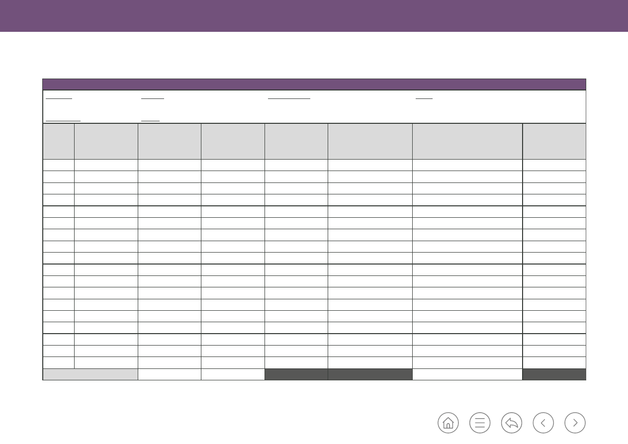
Table G.14  Typical details of maximum current on transformer with chiller/motor loads

DETAILS OF MAXIMUM CURRENT ON TRANSFORMER WITH CHILLER/MOTOR LOADS

PROJECT:

OWNER:

PLOT NUMBER:

AREA:

LV Panel No.:

Rating:

Sr. No.

Type of load 

(chiller, motor, etc.)

kW

No. of compressors 

per chiller

Starting current of 

one compressor/ 

motor

Full load current with all 

compressors/motors running 

+ other loads 

(A)

Max. current when largest compressor 

starts + all other compressors/ motors 

and other loads running 

(A)

Remarks 

(model no., make, type 

of starter, etc.)

Total 

Dubai Building Code

Part G: Incoming utilities

G 50

Table G.15 gives the maximum demand permitted at an 

MDB connected to DEWA’s supply  

feeder/transformer for the distribution of normal 

residential and commercial premises without 

connecting large motor loads.

Item

Feeder/transformer rating (A)

Load (kW)

1

60 A – feeder

30

2

100 A – feeder

50

3

125 A – feeder

60

4

160 A – feeder

80

5

200 A – feeder

100

6

300 A – feeder

150

7

400 A – feeder

200

8

1,000 kVA transformer

800

9

1,500 kVA transformer

1,200

Item

Transformer rating (kVA)

Load (kW)

1

1,500 kVA transformer 

950

2

1,000 kVA transformer

650

Table G.15 

Limit of maximum demand loads

Table G.16 

Limit of maximum demand air conditioning loads

DEWA transformers supplying motors and air 

conditioners (maximum individual loads not exceeding 

100 kW) shall be limited to the connected loads given 

in Table G.16.

Where DEWA transformers supply motors and air 

conditioners whose individual loads exceed 100 kW, 

the maximum TCL shall be subject to approval by 

DEWA. 
To ensure the safety of the transformers and 

the equipment, approval takes into account the 

equipment’s technical specification, including:

a)  the rating;
b)  the type of starters;
c)  the maximum starting current;
d)  the number of compressors/motors; and
e)  its stages of operation.
The overload protective device/incomer circuit 

breaker in the LV panels/MDBs shall be set at the 

corresponding design current.
Other methods of establishing maximum demand are 

permitted, where calculated by a qualified electrical 

Engineer with a suitable degree of knowledge and 

experience of the diverse applications of a particular 

installation. The design method and proposed diversity 

at each level of the distribution shall be submitted to 

DEWA for approval. They shall also be clearly indicated 

in the design drawings and schedules submitted to 

DEWA.

G.4.17  Design criteria for the installation of 

conduits, trunking, trays and accessories

G.4.17.1  Trunking and conduits

Trunking and conduits shall be selected to meet the 

requirements of G.4.11.
As far as possible, trunking and conduit runs from 

electrical switchrooms to individual consumer DBs 

shall be routed only within common electrical service 

routes and riser ducts.

Long trunking and conduit runs from electrical 

switchrooms located on the ground floor to consumer 

DBs located on upper floors shall not be installed 

unless unavoidable. Where armoured cables are used, 

they shall be installed in cable trays.
Cable trunking may be used for housing single core 

LSF cables where the installation of conduits is difficult 

due to space limitations.
Surface exposed trunking and conduit installations 

shall, as far as possible, have straight runs with 

branches at right angles only.
Draw-in boxes shall be provided in all straight conduit 

runs exceeding 15 m. Conduit runs having 90º bends 

shall be provided with draw-in boxes for every two 

bends.
Trunking and conduit shall be completely installed 

before any cable is drawn in.

Dubai Building Code

Part G: Incoming utilities

G 51

Draw-wires shall be provided in all concealed conduits (and ducts) with the ends 

left free at the outlet boxes for pulling the wiring cables. Permitted cable routes for 

concealed cables are illustrated in Figure G.19.

Figure G.19 

Permitted cable routes for concealed cables within walls with a depth of less than  

50 mm depth. (© Institution of Engineering and Technology. Figure based on Figure 2.3.3 in Institution of 

Engineering and Technology, 2018. Electrician's guide to the building regulations 

[Ref. G.2]

)

Key

01: No protection needed

02: Protection required unless depth greater than 50 mm

All the trunking and conduit runs shall be free from sharp edges and burrs 

throughout their lengths. Suitable grommets and bushes shall be provided at the 

terminal outlets.
Trunking and conduit runs shall be supported at regular intervals (see Table G.17 to 

Table G.19).

Method of installation

Spacing of support (mm)
Steel

Rigid PVC

Horizontal

1,500

1,000

Vertical

1,800

1,200

Method of installation

Spacing of support (mm)
Steel

Rigid PVC

Horizontal

1,200

1,000

Vertical

1,500

1,200

Method of installation

Spacing of support (mm)
Overall diameter 

20 mm to 40 mm

Overall diameter 

>40 mm

Horizontal

350

600

Vertical

600

800

Table G.17 

Trunking – Maximum spacing of clips, cleats, saddles or supports

Table G.18 

Conduit – Maximum spacing of clips, cleats, saddles or supports

Table G.19 

Armoured cables – Maximum spacing of clips, cleats, saddles or supports

Dubai Building Code

Part G: Incoming utilities

G 52

Entries to trunking shall be placed to prevent the 

ingress of water and all dead ends shall be closed. Only 

unbroken lengths of trunking shall be used for crossing 

partitions and walls.

Where cable trunking passes through walls, floors or 

other barriers, it shall be provided with a continuous 

cover.

Where cable trunking penetrates fire resistance 

rated floors, walls, partitions or ceilings, the openings 

remaining after passage of the trunking systems shall 

be sealed with an approved fire stopping system in 

accordance with Section 3, Ch. 1 of UAE  

FLSC 

[Ref. G.1]

.

The trunking shall be provided with separate 

compartments for the different types of circuits in the 

following situations:
a)  where a common cable trunking is used for housing 

both power and communication circuits; or

b)  for housing circuits operating at different voltages.
All bends, tees and other accessories of cable trunking 

shall be of substantial sections and of the same quality 

as the trunking itself.
The different sections of trunking shall be bonded by 

copper links. Trunking shall not be used as ECC.
The minimum internal radius of any bend or elbow 

fitting in a conduit shall be 2.5 times the diameter of 

the conduit, as shown in Figure G.20.

Figure G.20  Minimum internal radius of conduit elbow fitting

All terminal and intermediate ends of PVC conduits 

shall be firmly secured with suitable adhesives as 

recommended by the manufacturer.
Circuit wires shall be bunched and installed in vertical 

trunking runs. They shall be clamped/secured within 

the trunking at regular intervals not exceeding 2 m, and 

at the terminal ends.
Standard conduit boxes, draw-in boxes and mounting 

boxes of light fittings and appliances shall be fixed 

to the building structure independently of the wiring 

conduits.

All exposed threads, tool-marks or visible damage to 

the protective finish of the steel trunking and conduits 

shall be coated with zinc rich paint immediately after 

installation.
Suitable expansion couplers shall be provided in all 

trunking and conduit runs at the expansion joints in 

the building structure. They shall also be provided at 

regular intervals in all runs exceeding 7 m in length or 

as recommended by the manufacturer.
Suitable purpose-made boxes with adaptors, ceiling 

roses, etc. shall be provided at all individual outlet 

points of the wiring installations.

Light fittings used to house tungsten filament and 

halogen lamps shall be segregated protected by PVC 

sheathing and terminal outlet boxes such as to prevent 

degradation due to the associated high temperatures.
Conduit runs concealed within the building structure 

shall be provided with not less than 10 mm of screed 

cover.
When the trunking and conduit runs are installed 

with chases in the building structure, they shall be 

firmly fixed at regular intervals in accordance with the 

manufacturer’s recommendations, using purpose-made 

crimpers and/or saddles.

The standard conduit boxes, draw-in boxes, floor-

outlet boxes, etc. shall be installed with the cover/lid 

flush with the outer finish of the building structure 

(see BS 4662, BS 5733, BS EN 61535).

Dubai Building Code

Part G: Incoming utilities

G 53

Only flush type switches, socket outlets and 

accessories shall be used for concealed wiring.

Where conduit and or conduit fittings are attached 

to equipment, smooth bore male brass brushes and 

flanged coupling shall be used.

Except where provision is made for fastening, conduits 

shall be saddled to the structure of the building in 

accordance with the following:
1)  within 150 mm of each terminal angle box, bend 

or other conduit fittings;

2)  at maximum intervals of 1.5 m from couplings and 

through fittings.

Through type draw boxes shall be counted as part of a 

straight run conduit.
Non-metallic conduits shall not be used in the 

following locations and circumstances:
i)  where the conduit is exposed to outside ambient 

temperatures;

ii)  where the conduit is at risk of being affected 

by chemicals which cause deterioration in its 

construction;

iii)  plant rooms; 
iv)  elevator motor rooms;
v)  elevator shafts.
All conduit accessories shall be factory-made sections 

and of the same quality as the conduit itself.

G.4.17.2 

Flexible conduits

Flexible conduits shall not be used for complete fixed 

wiring installations. They shall only be used as and 

where permitted.

A flexible conduit run shall be not more than 2.5 m in 

length.

Metallic flexible conduits may be used for connecting 

electrical motors and other equipment to the fixed 

wiring, subject to adjustment of position and vibration.

Flexible conduits shall only be run exposed and shall 

be so positioned that they are not susceptible to 

mechanical damage. Wherever necessary, flexible 

conduits shall be supported in accordance with the 

manufacturer’s recommendations.

The end of flexible conduits shall be securely anchored 

to the fixed conduit or equipment to which it is 

attached. Approved flexible conduit adaptors shall be 

used that maintain effective mechanical continuity 

without distorting the conduit.

Flexible conduit shall not be used as part of the 

earth conductor. A separate earth conductor shall 

be installed to meet the same requirements for rigid 

conduit installation.

G.4.17.3  Cable trays

Trays for supporting cables shall be used in 

warehouses, industrial plant and equipment rooms, 

cable trenches, shafts in buildings, etc.
The type and material of the cable trays shall be 

selected to suit individual site locations and shall meet 

the relevant requirements specified in G.4.11. 

The cable trays shall be supported at regular intervals 

with purpose-made supports (see Table G.19).
Cable trays installed in outdoor locations and in 

locations where cables are exposed to the sun shall 

be provided with sun-shade covers. Covers shall be 

secured to the trays, and adequate ventilation provided, 

in accordance with the manufacturer’s instructions.
Cables shall be fastened securely by purpose-made 

clips, cleats or saddles and spaced as shown in  

Table G.19. 
Cable ties shall not be used to support multicore cables 

installed on cable trays that are fitted vertically.

Cable trays shall not be used in locations where they 

are likely to be subjected to severe physical damage.

Sufficient space shall be provided and maintained 

around cable trays to permit access for installing and 

maintaining the cables without causing unnecessary 

damage. Vertical clearance above the tray shall be 

not less than 1.5 times the height of the tray, or 

as given in the cable and cable tray manufacturer’s 

recommendations. 

Dubai Building Code

Part G: Incoming utilities

G 54

Cable trays shall be installed as complete systems with 

bends and other accessories. Each run of cable trays 

shall be completed before the installation of cables. All 

sharp edges, burrs and projection shall be removed, 

and the tray shall be finished smooth to prevent injury 

to cables.
Metallic cable trays shall be bonded together using 

copper links, but shall not be used as an ECC.
Cable trays shall be installed in such a way as to 

provide ease of access to cables through the route.

Where cable trays penetrate fire rated floors, walls, 

partitions or ceilings, the openings remaining after 

passage of the wiring systems shall be sealed with 

an approved fire stopping system in accordance with 

Section 3, Ch. 1 of UAE FLSC 

[Ref. G.1]

.

G.4.18  Design criteria for the installation 

of cables, equipment, accessories and wiring 

systems

G.4.18.1  Armoured cables

Armoured cables shall be installed in one of the 

following ways:
a)  directly buried in the ground;
b)  drawn through ducts;
c)  laid in concrete trenches;
d)  cleated to a wall;
e)  mounted on cable trays.
Cables shall be installed and used in association with 

other equipment in accordance with BS 7671. In 

environments or installations not described within the 

DBC, the appropriate regulations and standards shall 

be observed.
The current-carrying capacity of cables shall be 

determined after applying suitable correction factors 

based on the installation method of the cables.
Cables shall be selected ensuring voltage drops within 

the limit described in G.4.7.3.
Only armoured cables shall be used for underground 

installations. Precautions shall be taken to avoid 

mechanical damage to the cables before and during 

installation. Cables shall be laid as shown in  

Figure G.21. Where protective covers are required, they 

shall be centred over the cables, throughout  

their length.

Figure G.21 

Typical armoured cable installation below ground

Key

01: Ground

02: Warning tape at 300 mm below ground

03: 50 mm overlap on either side

04: Armoured cable at 900 mm below ground

05: 150 mm impervious soil layer

Dubai Building Code

Part G: Incoming utilities

G 55

Where cables pass underneath driveways or roads, 

PVC-U ducts shall be provided with heavy duty (HD) 

manhole covers. 
Cable routes shall be marked by cable route markers/

marking tape, placed at maximum intervals of  

10 m along straight runs and 2 m at deviations.  

Route markers shall indicate the voltage level in Arabic 

and English, as shown in Figure G.22.

Figure G.23 

Cable bending radius

No joints shall be included in any cable runs in the 

consumer’s fixed wiring installation.
Where busways penetrate fire rated floors, walls, 

partitions or ceilings, the openings remaining after 

passage of the wiring systems shall be sealed with 

an approved fire stopping system in accordance with 

Section 3, Ch. 1 of UAE FLSC 

[Ref. G.1]

.

Cable glands used for armoured cables shall be of brass 

compression type, conforming to BS 6121, with earth 

tags and PVC shroud.
All terminations of cable conductors shall be 

mechanically and electrically sound. Terminations shall 

be made using a terminal or compression type socket/

lug, approved by DEWA. Terminations shall not impose 

any mechanical strain on the terminal or socket/lug.
Separate ECCs shall be installed and terminated for 

each feeder/circuit, as specified in G.4.19.

Single core cable shall be arranged in trefoil formation. 

Non-ferrous cable gland plate shall be used for 

termination of single core armoured cables.  

The armour shall be earthed.
No cables shall run in an elevator or hoist shaft unless 

the cables are part of the elevator/hoist installation.

Figure G.22 

Typical cable route marker (DEWA)

Heavy duty conduit shall be provided for motor 

connections, external applications and locations subject 

to vibration, risk of mechanical damage or exposure to 

moisture.

Cables shall be installed on cable trays at specific 

locations and as stipulated in G.4.11.
In the event of crossing or proximity of underground 

telecommunication cables and underground power 

cables, a minimum vertical clearance of 100 mm shall 

be maintained.

For cables in fixed wiring installations, the internal 

radius of the bend shall be not less than eight times 

the cable diameter (see Figure G.23).

Dubai Building Code

Part G: Incoming utilities

G 56

G.4.18.2  Distribution boards

All DBs shall be installed in locations which are 

accessible at all times for operation, testing, inspection, 

maintenance and repair.

MDBs, SMDBs or final DBs shall not be installed in the 

following locations:
a)  bathrooms and toilets;
b)  damp or wet locations;
c)  bedrooms;
d)  kitchens;
e)  above sinks;
f)  store rooms;
g)  rooms with an ambient temperature exceeding the 

ambient design conditions of the equipment;

h)  dangerous or hazardous locations;
i)  below any staircase.

All MDBs, SMDBs or final DBs shall be selected and 

designed in accordance with G.4.12.
DBs shall incorporate means for isolation of mains 

supply in the form of either a circuit breaker or an 

incomer isolator, as applicable.
Every circuit breaker or fuse within the DB shall be 

identified and labelled to indicate the apparatus or 

circuit it controls. Table G.12 and Table G.13 show 

typical single-phase and three-phase DB schedules.

Each final DB shall supply only the circuits in the floor 

area where the DB is located, as shown in Figure G.24, 

except for applications such as staircase and common 

corridor lighting in high-rise buildings.

01

01

01

01

02

Figure G.24 

Indicative electrical distribution diagram

Figure G.25 

Maximum DB mounting height diagram

Key

01: DB

02: SMDB

Key

01: DB

02: FFL

In multi-consumer  installations, each consumer’s DBs 

shall be installed within the respective consumer’s 

premises (e.g. retail unit, apartments, etc.) and shall be 

near to the entrance of the premises.
Incoming supply cable installed to any DB shall be 

segregated and identified from the outgoing circuit 

cables/wiring.

All DBs shall be installed flush or surface mounted at a 

maximum height of 2 m to the top of the DB as shown 

in Figure G.25.
All LV panels of 1,600 A and above shall be of form 


4 type.

2 m

01

02

Dubai Building Code

Part G: Incoming utilities

G 57

500 - 1,800

500 - 1,800

01

01

02

03

G.4.18.3 

Busbar trunking systems (busways/bus 

risers)

Busways shall be installed only where adequate access 

is available for inspection and repair throughout their 

entire length.
The design, manufacture, testing and performance of 

the busbar trunking system shall be in accordance with 

BS EN 61439. The IP rating shall be selected based on 

the location, as described in BS EN 60529.
Each piece of busbar trunking shall be subject to the 

following factory tests: 
a)  3.5 kV dielectric test for 4 s;
b)  1,000 V Megger test in accordance with BS 7671. 

Test certificates for these tests shall be produced 

during DEWA inspection.
The busbars shall be totally enclosed in an 

unventilated, low impedance sandwich design. The 

busbar trunking shall be sandwiched throughout its 

entire length and shall not be flared at tap-points.

Onsite, each piece and run of busbar trunking shall be 

Megger tested at 1,000 V before and after installation.
Busbar risers proposed for installation in high-rise 

buildings shall be designed in such a way as to ensure 

reliability of power supply. In the event of outage of the 

respective busbar riser, not more than 12 floors shall 

be interrupted.

Connections to switchgear shall have flanged end units 

of specific design and shall be manufactured by the 

busbar trunking manufacturer.
The busbar trunking shall be aligned and securely 

fixed at centres of not more than 1.5 m or as 

recommended by the manufacturer. The busbar 

trunking manufacturer shall supply galvanized fixing 

brackets, comprising hanger clamp, fixing channel and 

damping screw, as means of support to take the weight 

of the busbar. Additional supports shall be provided 

where required and as recommended by the trunking 

manufacturer.
The complete busbar trunking system shall be of the 

type, size and location indicated in the DEWA approved 

drawings.
The busbar shall carry its rated current without 

exceeding 55 ºC (or an ambient temperature of 50 ºC 

at 90% relative humidity) in any plane without 


de-rating and without affecting the DEWA power 

supply requirements.
Where a busbar trunking system is installed on the 

supply side of any DEWA kWh metering, provision for 

sealing by DEWA shall be made as specified in G.4.5.

The phase busbar, neutral bar and earth bar shall be of 

copper, identified by colour as given in Table G.8. The 

neutral bar shall be of the same cross-section as the 

phase busbar.

ECCs and equipotential bonding shall be provided as 

specified in G.4.19.
Where the busway passes through fire rated floors, 

walls, partitions or ceilings, the openings remaining 

after passage of the wiring systems shall be sealed 

with an approved fire stopping system in accordance 

with Section 3, Ch. 1 of UAE FLSC 

[Ref. G.1]

.

Tap-off units installed in a busbar riser at each floor 

level shall be at the height shown in Figure G.26. The 

tap-off units shall have adequate access for operation, 

maintenance and replacement.

Figure G.26 

Busbar tap-off mounting height requirement

Key

01: Tap off

02: MDB/SMDB

03: Busbar

Dubai Building Code

Part G: Incoming utilities

G 58

G.4.18.4  Segregation of circuits, phases and 

wiring systems

All wiring and accessories shall be selected and 

installed to suit individual locations. They shall conform 

to G.4.11 and the following requirements. 
Circuits from different DBs shall not be installed in a 

common conduit or trunking.
The circuit wires of individual categories and of 

different voltage grades shall be installed in separate 

conduits, or segregated with barriers where installed in 

the same trunking run.
The circuit wires of individual categories (such as 

lighting, power and emergency) shall be segregated 

with barriers in trunking runs or installed in separate 

conduits.
Where residential premised are supplied with a  

three-phase supply, the light fittings, socket outlets, 

water heaters, cookers and other single-phase 

apparatus in any room shall not be connected to 

more than one phase, unless this is unavoidable. If 

connection to more than one phase cannot be avoided, 

a minimum distance of 2 m shall be maintained 

between outlets, accessories or appliances connected 

to different phases. 

Where a switch box contains more than one phase,  

for group switching, approved switch boxes with phase 

barriers shall be used and labelled to indicate that  

400 V is present in the back box. All circuit wires shall 

be identified by colour as shown in Table G.8. 

Where a wiring system is in close proximity to 

non-electrical services, the wiring system shall be 

segregated and protected against hazards that are 

likely to arise from the presence of the other service(s) 

in normal use. Provision shall be made for safe and 

adequate access to all parts of the wiring system which 

might require inspection, maintenance or replacement.

Switches controlling light fittings, water heaters, etc. 

shall not be installed in bathrooms. In kitchens and 

other areas where water is regularly used, switches 

shall not be mounted within 2 m of any water tap, wash 

basin or sink where possible. If there is insufficient 

space to allow for this, ceiling mounted, insulated,  

cord-operated switches shall be used.
Socket outlets shall not be installed in bathrooms.
Where luminaires have a track system, this shall 

conform to BS EN 60570.

Dubai Building Code

Part G: Incoming utilities

G 59

1,250

450

150

Figure G.27 

Typical mounting heights of electrical accessories

Figure G.28 

Typical electrical warning label

G.4.18.6 

Identification labels and notices

All sections of the consumer installation at the DBs 

shall be provided with identification labels to indicate 

the location and purpose of each protection device, 

piece of connected equipment and circuit. Instructions 

or caution notices for correct operation shall also be 

provided where necessary. All labels shall be in both 

English and Arabic as shown in Figure G.28. Font sizes 

shall be chosen to suit the individual application.

G.4.18.5  Mounting heights of accessories

Accessories (as described in G.4.13) shall be mounted 

as follows (and as shown in Figure G.27).

a)  All lighting switches, DP switches of air 

conditioning units and water heaters, ceiling fan 

regulators, shaver socket outlets, etc., provided as 

part of the electrical installation shall be mounted 

1.25 m above the finished floor level.

b)  13 A switched socket outlets used for general 

purpose shall be installed at 450 mm above the 

finished floor level. 13 A switched socket outlets 

provided in kitchens shall be installed 150 mm 

above the worktop. 

All switches shall be mounted in readily accessible 

positions.

Dubai Building Code

Part G: Incoming utilities

G 60

G.4.19  Earthing and earth leakage 

protection

G.4.19.1  General

Earthing systems shall be designed and installed in 

such a way that they remain safe and do not endanger 

the health and safety of persons or their surroundings. 

Every consumer installation shall be provided with 

a separate earthing system within the plot limits, 

installed and maintained by the consumer.
An earth system shall remain effective throughout the 

life of the plant. It is difficult in many cases to perform 

of continuity checks after installation; the system shall 

therefore be robust and protected from mechanical 

damage and corrosion where necessary.
Each consumer’s earthing system shall comprise 

the earth electrode(s) main earth lead conductor 

connected between the earth electrode(s) and the 

consumer’s main earthing terminal(s) or earth busbar.
ECCs shall be provided for every outgoing circuit from 

the MDB, SMDB and final DBs, equipotential bonding 

of all metalwork and exposed conductive parts and 

enclosures, etc. Guidance is available in BS 7430,  

BS EN 50522 and IEC 60364.
Selection of the earthing conductor material shall 

be based on its compatibility with the material of 

the earth electrode. For a conductor installed in the 

ground, the corrosive effect of the soil shall also be 

taken into account.

The consumer’s earthing system shall be connected 

to the DEWA earthing system [either the incoming 

supply cable armour or the earth continuity conductor 

(ECC), as approved by DEWA].

The following shall have separate earthing networks 

and shall not be connected to the main electrical 

earthing system:
a)  MV networks;
b) 

LV networks;

c) 

Extra LV networks;

d)  private generators;
e)  lightning protection systems.

The earthing system shall be of low electrical 

resistance, good corrosion resistance and able to 

dissipate high fault current repeatedly.
The consumer main earthing connection shall be 

a TN-S system (see Figure G.29). The exposed 

conductive parts of all the electrical equipment of the 

installation shall be connected by circuit ECCs to the 

main earthing terminal. The earth fault loop impedance 

shall be sufficiently low for the protective device (fuse, 

circuit breaker, RCD) to operate in the required time in 

the event of a fault to earth.

Figure G.29  Typical TN-S earthing arrangement (© British Standards Institute. Figure extracted from BS 7671:2018. Permission to reproduce extracts 

from British Standards is granted by BSI Standards Limited (BSI). No other use of this material is permitted).

Key

01: Source of energy

02: Protective conductor (PE)

03: Consumers’ installations

04: Source earth

05: Equipment in installation

06: Exposed-conductive-parts

Dubai Building Code

Part G: Incoming utilities

G 61

The neutral and earth conductors shall be kept 

separate. They shall not be connected together at 

the main earth terminal or at any other point in the 

consumer’s installation.
Where several installations have individual earthing 

arrangements, any common ECC shall be capable of 

either:
1) 

carrying the maximum fault current likely to flow 

through them; or

2)  being earthed within one installation only and 

insulated from the earthing arrangements of any 

other installation.

Foundation metalwork in concrete may be used as 

a ready made and effective earth electrode. The 

total electrode area formed by the underground 

metalwork of a large structure can be used to provide 

an earth resistance lower than that obtainable by 

other methods. It is important that consideration is 

given to the possibility of corrosion of the metalwork 

reinforcement. The products of corrosion occupy a 

greater volume than the original metal, and cracking 

might occur. 
Continuous earth leakage currents shall be mitigated 

by the designer of the electrical system. 

NOTE: Some earth leakage currents might be 

incompatible with other buried metalwork, including 

other types of earth electrode to which foundation 

metalwork might be bonded, such that it might be 

necessary to consider the need for cathodic protection.

Damage to the concrete in the form of cracking, due to 

arcing or the rapid evaporation of moisture, can occur 

where the long-term duration earth fault currents 

exceed the carrying capability of the electrode. This 

situation is unlikely to arise if the electrode has a 

resistance sufficiently low to avoid dangerous voltages 

to earth. Where, in structures made of bolted sections, 

the electrical continuity of the structural joints cannot 

be relied upon to form permanent and reliable earth 

bonds, bonding loops across these joints shall be 

installed.
Water mains shall not be used for earthing purposes. 

Metal pipes (e.g. for gas, oil, compressed air or 

drainage) carrying other services shall only be bonded 

to the protective conductors and not used for the sole 

means of earthing.
Earth electrodes shall not be installed at a distance 

from a metal fence less than the buried depth of the 

electrode, unless they are used for earthing that fence. 

This is to avoid the possibility of the fence becoming 

live and thus dangerous at points remote from the 

substation, or alternatively giving rise to danger within 

the resistance area of the electrode by introducing a 

good connection with the general mass of the earth.

G.4.19.2  Consumer’s main earth electrode

A minimum of one main earth electrode shall be 

provided for each incoming point of supply/consumer’s 

MDB, within the consumer’s premises. For installations 

with a main incomer of 200 A and above, a minimum of 

two earth pits shall be provided.
The earthing systems shall consist of copper 

conductors or steel rods (austenitic steel or copper 

clad) of appropriate dimensions, set with a driving 

pin and head driven to a minimum depth of 3 m. The 

earth electrode shall be installed inside a 300 mm × 

300 mm × 300 mm earth pit with inspection cover. 

The connection of the earthing conductor to the earth 

electrode or other means of earthing shall be made 

using compound filled, encapsulated or substantial 

clamps of non-ferrous material. 

NOTE: Uncoated buried copper is electro-positive 

to uncoated buried steel. When interconnected by 

a current-carrying conductor, these metals form 

an electrochemical cell that can cause accelerated 

corrosion of steel. 

The consumer’s main earth electrode shall be installed 

within 1.5 m of the MDB. Where more than one earth 

electrode is installed within the premises, they shall be 

spaced not less than 6 m apart. Load centres located 

laterally 50 m or more from the MDBs might require 

additional backup earthing.

Dubai Building Code

Part G: Incoming utilities

G 62

Apart from the risk of corrosion to the earthing 

system, the chemical treatment of soil has 

environmental implications and is not a long-term 

solution to meet a specified level of resistance. 


Coke breeze shall not be used due to its highly 

corrosive nature.

For each incoming DEWA supply/MDB, the main earth 

electrode resistance shall not exceed 1 Ω.

The resistance from any point of the earth continuity 

conductor (ECC) to the main earth electrode shall not 

exceed 0.5 Ω.

The consumer’s earth electrode resistance and the 

continuity of ECCs shall be periodically checked and 

maintained to ensure consumer safety as outlined in 

BS 4444.

Lightning protection earthing shall be separate from 

the earthing of the incoming DEWA supply/MDBs. A 

minimum distance of 7 m shall be maintained between 

the earthing inspection pits.

G.4.19.3 

Earth continuity conductor (ECC)

Every circuit in the MDBs, SMDBs and final DBs shall 

be provided with a separate green and yellow (G/Y) 

LSF insulated copper ECC. The minimum size of ECCs 

shall be selected as specified in Table G.20.

Cross-sectional 

area of phase/

neutral conductor 

(S) (mm

2

)

Minimum cross-

sectional area of 

ECC (G/Y LSF 

insulated copper 

conductors) (mm

2

)

Minimum cross-

sectional area 

of equipotential 

bonding 

conductors (mm

2

)

S ≤ 16

S

S/2
(not less than 6)

16 < S < 35

16

10

S > 35

S/2

S/4
(need not exceed 

25)

Table G.20  Minimum size of earth continuity cables (ECC)

ECCs shall be terminated with tinned copper lugs at 

both ends, on purpose-made earth terminals at:
a)  electrical equipment, apparatus and distribution 

switch gear;

b) 

light fittings;

c)  mounting boxes of switches and socket outlets.
All busbar risers installed for electrical distribution in 

high-rise buildings and other consumer installations 

shall incorporate an appropriately sized ECC either 

within, or run separately along, the riser. BS 7430 gives 

guidance on earthing and ECCs.

Joints shall be made such that their current-carrying 

capacity is not less than that of the conduit itself. 

Joints shall also have the same insulation, mechanical 

strength and protection properties as those of the 

wiring system or conduit of which they are part.

ECCs shall be covered with green and yellow LFC 

insulation and terminated with purpose-made lugs or 

fixings.

Where associated with circuits, ECCs shall be labelled 

at their termination points with circuit identification 

numbers.
Circuit ECCs shall run alongside the associated phase 

and neutral conductor.
The following shall not be used as an ECC:
1)  gas pipes;
2)  oil pipes;
3) 

metallic conduit, support wires or other flexible 

metallic parts;

4)  construction elements other than metalwork as 

described in G.4.19.1.

ECCs shall be protected against mechanical and 

chemical deterioration and electrodynamics effects in 

accordance with the manufacturer’s requirements.

Dubai Building Code

Part G: Incoming utilities

G 63

Where two ECCs are used, the ends of the ECC shall 

be terminated independently of each other at all 

connection points throughout the circuit, the DBs, 

junction boxes and socket outlets. To achieve this, an 

accessory shall be provided with two separate earth 

terminals.
Where the cable incorporates metallic armouring, this 

shall be clamped to the cable gland. The main earth 

conductors shall be placed such that the metallic cable 

sheaths can be reliable and readily connected to it by 

bonds made to the cable gland.
Earthing conductors shall be accessible for the 

connection of any detachable earthing devices used 

with the electrical equipment.

G.4.19.4  Earth leakage protection

Earth leakage protection shall be designed and 

incorporated in consumer installations in accordance 

with BS EN 61140 and IEC 61140.

The ELCBs/RCCBs shall generally conform to 


BS EN 61008-1 and BS EN 61009-1. Recommended 

values of operating current of ELCBs/RCCBs are 

specified in Table G.21, though the designer shall verify 

with the manufacturer’s recommendations.

Sr. No. Circuit/equipment/apparatus

Rated operating 

current (mA)

1

13 A switched socket outlets

30

2

Water heater/coolers/dishwashers

30

3

Refrigerator/washing machine and 

similar apparatus

30

4

Domestic water pumps

30

5

Jacuzzi pumps

10

6

Under water lighting

10

7

15 A switched socket outlets 

(general purpose)

30

8

General lighting

30/100

9

Flood lighting

100/300

10

Window/split type air conditioner

100

11

Fan coil/AHU/VAV

100

12

Package type air-conditioning unit

100/300

13

Chiller

100/500/1,000

14

Irrigation pump

100

15

Electric cooker

100

16

Industrial machine

100/300

17

Elevators/escalators/hoist

300/500

18

Neon sign

300

Table G.21 

Recommended value of operating current for ELCB/RCCB in 

consumer installations

NOTE 1: Grouping of circuits under one ELCB/RCCB 

is permitted for lighting circuits, general purpose 

switched socket outlets, single-phase equipment/

appliances, etc. The maximum number of circuits 

proposed under each group should be selected taking 

into account the building type and the possible 

interruptions.
NOTE 2: Wherever an uninterruptable power supply 

is required to provide power to equipment and 

circuits as part of a fire protection system (such as 

fire pump, jockey pump, sump pump, sprinkler pump, 

pressurization pump, smoke extract fans), a suitable 

earth leakage detection system with indication and/or 

alarm should be provided.

For industrial installations that are designed with 

common operating systems for plant and machinery, 

the earth leakage protection shall be selected taking 

into account the safety and operational requirements.

Operation of the ELCBs/RCCBs, earth leakage 

detection system, etc. shall be periodically checked 

and tested in accordance with the manufacturer’s 

recommendations to ensure consumer safety.
Earth leakage sensors/relays with alarm/indicators 

shall be provided for fire pumps, jockey pumps, 

submersible pumps, sump pumps, or other essential 

circuit/equipment with sensor settings that allow 

for pre-fault warning notification and fault warning 

notification.

Dubai Building Code

Part G: Incoming utilities

G 64

G.4.19.5  Equipotential bonding

All metalwork of the consumer’s installation, other than current-carrying parts, shall 

be provided with equipotential bonding conductors as shown in Figure G.30. This 

shall include, but is not limited to:
a)  cable armour;
b)  metal conduits;
c)  metal cable tray/trunking sections;
d)  metal accessory boxes;
e)  exposed metalworks of consumers’ appliances;
f)  apparatus;
g)  equipment;
h)  machines;
i)  building structures;
j)  metallic enclosures and parts;
k)  metal water pipes.
The cross-sectional area of equipotential bonding conductors shall be selected using 

Table G.20.
A main protective bonding conductor shall have a minimum cross-sectional area 

not less than half the cross-sectional area required for ECC of the installation, and 

not less than 6 mm

2

. A maximum cross-sectional area of 25 mm

2

 is sufficient if 

the bonding conductor is of copper or a cross sectional area affording equivalent 

conductance in other materials.
The equipotential bonding conductors shall be connected to the main earthing 

terminal within the consumer’s wiring installations. The continuity shall be tested and 

maintained by the consumer.

Figure G.30 

Typical example of main equipotential bonding of services (© Institution of 

Engineering and Technology. Figure based on Figure 5.6 in Guidance Note 8: Earthing and 

Bonding 

[Ref. G.3]

).

Key

01: Other extraneous conductive part

02: Water installation pipe

03: Circuit protective conductors

04: Gas installation pipe

05: Main protective bonding conductors

06: Earthing conductor

07: Means of earthing

Dubai Building Code

Part G: Incoming utilities

G 65

G.4.20  Power factor correction, harmonic 

and undervoltage (UV) relays

G.4.20.1  PF correction

The PF of every consumer installation shall be within 

the range of 0.9 lagging and unity (recommended value 

0.95 lagging).
All air-conditioning units/plants/equipment, machines, 

motors, light fittings with discharge lamps/mercury 

vapour/sodium vapour/fluorescent tubes, etc., shall 

be provided with capacitors or other approved means 

to achieve and maintain a PF of 0.95 lagging or above, 

throughout their normal working range.

For commercial premises that require DEWA service 

feeders of 200 A and above, where individual 

load compensation cannot be achieved, overall 

compensation at main or sub-main distribution levels 

shall be provided by incorporating capacitor banks with 

automatic regulated steps. For residential premises the 

limitation shall be a 400 A feeder.

The PF correction capacitor shall be a dry, 

encapsulated, sealed type conforming to IEC 61921.
Capacitors shall be enclosed or guarded to prevent 

accidental contact of conducting metal parts with 

exposed energized parts, terminals or buses associated 

with them.

Capacitors installed for PF correction shall be provided 

with the means for automatic, immediate discharge 

when the capacitor is disconnected from the source of 

supply.
The discharge circuit shall be either permanently 

connected to the terminals of the capacitor or 

capacitor bank, or provided with automatic means of 

connecting it to the terminals of the capacitor bank 

on removal of voltage from the line. Manual means of 

switching or connecting the discharge circuit shall not 

be provided.
The capacitors and associated components [such as 

PF regulator, indicating instruments, contactors (of 

capacitor switching duty), control switches, etc.] shall 

be designed and rated for operation based on:
a)  the electric supply;
b) 

the ambient conditions specified in G.4.6;

c)  the selection details recommended in G.4.13. 
Capacitor units shall be designed for temperature class 

D in accordance with IEC 61921.
The current-carrying capacity of conductors that 

connect a capacitor to the terminals of a motor or to 

motor circuit conductors shall be:
1)  a minimum of one-third of the current-carrying 

capacity of the motor circuit conductors; and

2)  a minimum of 1.5 times the rated current of the 

capacitor in all cases. 

An overcurrent device shall be provided in each circuit 

for each capacitor bank. A separate overcurrent device 

is not required for a capacitor connected on the load 

side of a motor overload protective device. The rating 

or setting of the overcurrent device shall be as low as 

practicable.

The capacitor banks installed for PF correction are 

major contributors to potential resonance. Such 

resonance conditions can magnify harmonic levels. 

Parallel resonance gives rise to a high impedance 

across the network and can cause voltage and current 

amplification. Network studies shall be carried out to 

determine the correct rating of capacitors and their 

operation without causing resonance. Mitigation 

measures shall be taken such as installing suitable 

harmonic filters or reactors. The capacitors shall 

be suitable for operation under harmonic current 

conditions. To minimize this risk of harmonic currents, 

harmonic filter reactors shall be provided in series with 

capacitors. Tuning of the capacitors, harmonic filter 

reactors shall be made below the lowest harmonic 

order present in the network.
The contactors used in the capacitor banks shall be 

able to withstand switching surge. Suitable means shall 

be installed to isolate each capacitor, capacitor bank, or 

capacitor installation from all sources of voltage and to 

remove the unit from service.

Dubai Building Code

Part G: Incoming utilities

G 66

All non-current-carrying metal parts of capacitors shall 

be earthed as specified in G.4.19.

Each capacitor shall be provided with a name plate 

indicating the following information:
i)  rated voltage;
ii)   frequency;
iii)  kVAr;
iv)  number of phases;
v)  discharge device;
vi)   name of the manufacturer.
Wherever a capacitor bank/panel is installed on the 

supply side of DEWA kWh metering, adequate sealing 

provision shall be made as specified in G.4.5.

In premises where capacitor banks are not installed and 

individual equipment is provided with suitable means 

for PF correction, a PF meter shall be provided in the 

MDB for displaying the PF. If PF deviates from the 

requirement specified by the designer, consumers shall 

arrange for PF correction equipment to maintain the 

PF close to 0.95 lagging.

The capacitor bank panel shall be provided with a 

suitably rated main incomer isolating switch. This shall 

be a three-pole isolator or MCCB. The handle of the 

incomer isolator or MCCB shall be interlocked with the 

door to ensure that the capacitor bank is de-energized 

when the door is open.

Capacitor banks shall be provided with forced 

ventilation. They shall have double enclosures to 

limit the temperature rise for outdoor/open to sky 

area installations. A trip mechanism with alarm shall 

be provided to operate in the event of failure of the 

ventilation/excess temperature rise.

G.4.20.2  Harmonics and rapid voltage changes

A consumer’s load shall not cause deviations of the 

voltage characteristics other than those permitted by 

BS EN 50160 and IEC 61000.
The on-site measurements to determine compliance 

with the harmonics limits and any excess deviations 

shall be carried out by the consumer. The following 

characteristics of a supply voltage shall be taken into 

account:
a)  power frequency;
b)  magnitude of the supply voltage;
c)  supply voltage variations;
d) 

rapid voltage changes and flickers;

e)  supply voltage dips;
f)  short interruptions of the supply voltage;
g)  long interruptions of the supply voltage;
h)  temporary power frequency over voltages;
i)  transient over voltages;
j)  supply voltage unbalance;
k)  harmonic voltage;
l)  inter-harmonic voltage;
m) mains signalling voltage.

G.4.20.3 

Undervoltage (UV) relays with auto 

reset timer

All air-conditioners and air-conditioning units/plants/

equipment installed within the consumer’s installation 

shall be provided with UV relays that trip the circuit 

breakers/contactors associated with these relays. 
The tripping shall occur immediately and without any 

intentional time delay if the supply voltage drops to or 

below 75% of nominal and remains at or below 75% 

for a duration of 0.2 s. Tripping shall not occur if the 

supply voltage recovers above 75% within 0.2 s. 

The UV relay’s auto-reset timer shall have an 

adjustable time setting between 5 min and 10 min. 

The circuit breakers/contactors associated with the 

UV relay shall have an auto-closing facility to restore 

supply to the chillers/air conditioning units, after 

normalization of supply voltage, when the relay is 

reset automatically. The auto-closing facility shall 

have a motorized operation. The auto-reset timer of 

the UV relays shall be set at values specified in the 

manufacturer’s schedules, approved by DEWA, to suit 

individual installation. Necessary provision for sealing 

may be incorporated in the relay to restrict access for 

adjustments of the setting. 

Dubai Building Code

Part G: Incoming utilities

G 67

UV relays with auto-reset timers shall normally be 

incorporated within the respective air-conditioning 

unit/equipment or in their control panels. For normal 

air-conditioners, UV relays with auto-reset timers may 

be provided within the consumer’s DB for individual or 

group of air-conditioning units. Prior approval shall be 

obtained from DEWA for each application.
The UV relays shall only be applied to trip the 

respective air-conditioning units/plant or equipment 

sensitive to voltage variations. The UV relays shall not 

be applied to trip LV incomer circuit-breakers/ACB 


within the main LV panel. The UV relays with 

associated controls shall be checked and maintained 

regularly. The 75% voltage threshold and tripping time 

of the air-conditioning units/plants/equipment shall be 

confirmed to DEWA after installation.

G.4.21  Construction sites

G.4.21.1  General

Assemblies for the distribution of electricity on 

construction sites shall conform to BS 4363 and BS 

EN 61439.

Equipment shall be identified by a temporary label 

identifying the supply location, and shall be compatible 

with the particular supply from which it is energized. 

It shall only contain components connected to a single 

installation.

Cables shall not be installed across a site, road 

or walkway unless the cable is protected against 

mechanical damage. 
All cables used on construction sites shall have a 

metal sheath and/or armour, both of which shall be 

effectively earthed and continuous.
Wiring systems shall be arranged such that no strain 

is placed on the terminations of conductors, unless the 

terminations are designed for this purpose.
Assemblies for construction sites shall incorporate 

suitable devices for switching and isolating the 

incoming supply.
A circuit breaker shall be provided for isolating the 

incoming supply. The circuit breaker shall either be 

suitable for securing in the off position by padlock, or 

installed inside a lockable enclosure.
Safety and standby supplies shall be connected by 

means of devices arranged to prevent interconnection 

of the different supplies.
Metering cabinets, DBs and wiring installations 

installed outdoors shall be weatherproof  

(IP 65 in accordance with BS EN 60529).

G.4.21.2  Wiring systems and distribution boards

Cables which are not installed in conduit or trunking 

shall be:
a)  armoured;
b)  protected against accidental or deliberate 

interference by persons; and

c)  protected against the weather.
A means of emergency switching shall be provided on 

the supply to all equipment from which it might be 

necessary to disconnect all live conductors in order to 

remove a hazard.
Equipment shall be located, and notices displayed, 

in such a way as to facilitate immediate emergency 

disconnection of the electricity supply. Locking 

arrangements shall be provided that can be removed 

in an emergency (e.g. panic bar or keys available in a 

break-out box).
Where a proposal for more than one feeder means 

that MDBs are installed at different locations, the 

emergency power out facility shall be provided at a 

single location. 

It might be necessary to use a reduced LV supply 

for portable tools where there is a high exposure to 

potential damage, or where persons are required to 

operate such equipment in confined spaces or other 

hazardous circumstances. A reduced LV shall be used 

where deemed necessary.

Dubai Building Code

Part G: Incoming utilities

G 68

Temporary electrical systems for entertainment and 

similar purposes shall be provided in accordance with 

BS 7909.

G.4.21.3  Earth leakage protection

In addition to the overcurrent and short-circuit 

protection, every circuit shall be protected for earth 

leakage.
All of the following shall be protected with an  

ELCB/RCCB of rated operating current 30 mA: 

a) 

final sub-circuits connected to 13 A switched 

socket outlets;

b)  portable tools;
c)  equipment.

A 100 mA ELCB/RCCB shall be provided for the 

protection of other lighting circuits,  

fixed equipment, etc. unless otherwise specified.

The consumer shall check and test the earthing 

systems, operation of ELCBs/RCCBs, wiring 

installation, etc. regularly to verify that the installation 

is safe, and shall take remedial action if necessary.

Dubai Building Code

Part G: Incoming utilities

G 69

G.5  Electric vehicle (EV) charging points

G.5.1 

Charging modes

G.5.1.1 

General 

IEC 61851 specifies four different modes of conductive charging for electric vehicles. The four modes are summarized in G.5.1.2 to G.5.1.5.

Figure G.31 

Electric vehicle Mode 1 charging

Figure G.32 

Electric vehicle Mode 2 charging

Key

01: Battery

02: EV inlet

03: Connector

04: On-board charger

05: Plug

06: Socket outlet

Key

01: Battery

02: EV inlet

03: Connector

04: On-board charger

05: Plug

06: Socket outlet

07: In-cable control box

G.5.1.2 

Mode 1 charging

Mode 1 charging is illustrated in Figure G.31. Alternating current (AC) is delivered 

to the on-board charger of the EV, via a standard socket outlet and a charging 

cable without communication function. An RCD for shock protection is provided on 

the supply side of the fixed electrical installation. Mode 1 is not suitable for longer 

periods of charging at home or the work place. 
Mode 1 is not permitted due to the lack of safety measures associated with this 

mode of charging.

G.5.1.3 

Mode 2 charging

Mode 2 charging is illustrated in Figure G.32. The charging cable assembly 

incorporates an in-cable control box. The fixed electrical installation for the charging 

facility is similar to that of Mode 1 except that the final circuit, protective device and 

socket shall be of a suitable rating for the connected load, and shall not exceed 32 A, 

in order to cater for the higher level of charging current.

Dubai Building Code

Part G: Incoming utilities

G 70

G.5.1.4 

Mode 3 charging

Mode 3 charging is illustrated in Figure G.33. It employs dedicated EV service 

equipment (EVSE) and a charging cable assembly. The control pilot cable of the 

charging cable assembly allows communication between the EVSE and the on-board 

charger. Communication functions include:
a) 

verification of connection with the EV;

b)  continuous checking of protective earth conductor integrity;
c)  energization and de-energization of the supply;
d)  selection of the charging rate.

Figure G.33 

Electric vehicle Mode 3 charging

Figure G.34 

Electric vehicle Mode 4 charging

06

05

Key

01: Battery

02: EV inlet

03: Connector

04: On-board charger

05: Plug

06: Socket outlet

07: AC charger facility

Key

01: Battery

02: EV inlet

03: Connector

04: DC quick charging facility

G.5.1.5 

Mode 4 charging

Mode 4 charging is illustrated in Figure G.34. It employs an off-board charger to 

deliver direct current to the battery, bypassing the on-board charger. This mode 

can charge an EV in a relatively short time because a higher electrical power is used 

(ranging from 20 kW to 120 kW).

NOTE: Maximum charging capacity of a DEWA charger shall be limited to 25kW or 

below per charging outlet, subject to available load capacity.

Dubai Building Code

Part G: Incoming utilities

G 71

G.5.2 

EVSE design requirements

For the permitted charging modes described in G.5.1.3 

to G.5.1.5, the following requirements shall be met.
a)  The following general requirements shall be met.

1)  Installation of a private charging outlet shall be 

subject to prior DEWA approval. 

2)  The design of EVSE shall enable maintenance 

and service work to be carried out safely.

3) 

EVSE shall be installed with sufficient space 

around it, in accordance with the manufacturer’s 

instructions, to allow for ventilation and cooling 

of the equipment.

4)  EVSE shall be installed in such a way as to 

minimize the distance between the EV inlet and 

the charging equipment.

5)  EVSE shall not be installed in locations where 

a potentially explosive atmosphere exists, such 

as petrol stations. Where such locations require 

EVSE, it shall be installed outside the hazardous 

zone.

b)  The following requirements shall be met for circuits.

1)  EVSE shall be supplied by a separate and a 

dedicated radial circuit. The radial circuit shall 

supply no other loads, except for ventilation 

equipment required by the EVSE. 

NOTE: More than one EVSE can be fed from the 

same supply circuit, provided that the combined 

current demand of the equipment does not 

exceed the rating of the supply circuit.

2)  Cables supplying EVSE shall be mechanically 

protected by means of metal sheath/armour, or 

installed inside a conduit made from either:
i)  rigid steel;
ii)   plastic;  or
iii) PVC.

3) 

Each final circuit shall be sized to carry the rated 

current of the EVSE, with limited voltage drop 

as required.

4) 

Where the final circuit supplies more than one 

EVSE, there shall be no diversity. A diversity 

factor (usually greater than one) may be used 

for a dedicated distribution circuit supplying 

multiple EVSE charging points, provided that 

load control is available.

c)  The following requirements shall be met for sockets 

and connectors.
1)  One socket outlet and/or vehicle connector shall 

be used to charge one EV.

2)  EVSE shall be installed such that the main 

operating controls and any socket outlet are 

between 0.75 m and 1.2 m above ground.

3)  The EV manufacturer’s instructions shall be 

followed when determining the type of socket 

outlet to be installed.

d)  The following requirements shall be met for 

isolation and switching.
1)  A means of isolating the supply to the EVSE 

circuit shall be provided, in accordance with 

G.4.13.2. The isolating device shall be:
i)  capable of being locked in the open position;
ii)   located in a position that is readily accessible 

for maintenance purposes; and

iii) 

suitably identified by marking and/or 

identification.

2)  Where an emergency switch is provided, it shall: 

i)  be located in a position that is readily 

accessible, in accordance with the 

manufacturer’s recommendations;

ii) 

be suitably identified by marking and/or 

labelling; and

iii) disconnect all live conductors, including the 

neutral.

e)  The following requirements shall be met for 

protection.
1)  EVSE and all associated equipment shall 

be selected and erected in such a way as to 

minimize the risk of overloads and short-

circuits.

2) 

Each final circuit shall be individually protected 

against fault current by a suitably rated 

overcurrent protective device.

Dubai Building Code

Part G: Incoming utilities

G 72

3)  Basic protection against electrical shock shall be 

provided by automatic disconnection of supply 

or electrical separation (see G.4.13.2). 

4)  Every charging point shall be individually 

protected by a 30 mA RCD. The RCD shall 

disconnect all live conductors, including the 

neutral.

5) 

The requirements of G.4.19 shall be met on final 

circuits.

f)  The following requirements shall be met for 

labelling.
1) 

The labelling and identification requirements 

listed in G.4.18.6 shall be met, together with the 

following.

2)  All labels on EVSE shall be:

i)  clear;
ii)   easily  visible;
iii) written in both Arabic and English; and
iv) 

constructed and affixed to remain legible for 

as long as the enclosure is in use.

3)  An operation instruction for the charging facility 

shall be displayed at a prominent location at all 

parking spaces with EVSE. The instruction shall 

include the following information:
i)  rated voltage (V);
ii) 

frequency (Hz);

iii) current (A); and
iv)  number of phases.

4)  Directional signage inside and outside car parks 

is recommended to direct EV drivers to parking 

spaces with EVSE.

Dubai Building Code

Part G: Incoming utilities

G 73

G.6  Renewable energy

G.6.1 

General

As a type of renewable energy, solar energy is clean 

and secure. DEWA encourages the use of solar energy 

to reduce reliance on traditional energy sources  

(such as gas, oil and coal), which are diminishing.
The onsite generation of electricity from a solar PV 

shall be by a solar grid-connected system. The grid-

connected solar generator shall be connected to the 

DEWA network, and operated and maintained in 

accordance with applicable legislation 

[Ref. G.4]

 and 

DEWA Shams Dubai regulations 

[Ref. G.5]

. System 

documentation requirements are described in G.6.2.

NOTE 1: The connection of a solar PV system or 

distributed renewable resource generation (DRRG) to 

the DEWA grid is subject to DEWA approval.
NOTE 2: Detailed technical requirements are set out in 

DEWA Technical publications and resources 

[Ref. G.6]

.

The designer shall comply with DEWA specifications, 

acceptable standards, procedures and other 

requirements published on DEWA website  

(Shams Dubai section). The requirements are updated 

regularly and form an integral part of the DBC.
Solar power generation systems shall conform to 

Section 2, Ch. 14 of the UAE FLSC 

[Ref. G.1]

 and  

this section.

Building attached photovoltaics (BAPV) systems 

attached to roofs, excluding curved or special roofs, 

are permitted to achieve a minimum fire classification 

of Class C when tested as per the test standards in 

Section 2.2.4, Ch. 14 of the UAE FLSC 

[Ref. G.1]

.

The minimum fire classification permitted for building 

integrated photovoltaics (BIPV) and BAPV systems 

other than the above shall be confirmed with DEWA 

and DCD upon commencement of design.

G.6.2 

System documentation requirements

Consultants and Contractors registered with DEWA 

for activities related to grid-connected solar PV 

systems (DRRG Solar PV Consultants and DRRG 

Solar PV Contractors) shall follow the DEWA 

guidelines published on the DEWA website for these 

requirements. Applications for solar connections shall 

be submitted online and shall include the following 

documents:
a)  basic system information;
b)  details of the system designer;
c)  details of the system installer, operation and 

maintenance procedure.

NOTE: Detailed requirements are set out in DEWA 

Connection guidelines for distributed renewable 

resources generators connected to the distribution 

network 

[Ref. G.7]

.

G.6.3 

Wiring diagram datasheets 

An annotated/table form single line wiring diagram 

that meets the requirements of DEWA Shams Dubai 

regulations 

[Ref. G.5]

 shall be uploaded with the 

DEWA application. It shall include the following 

information: 
a) 

PV array general specifications:

1)  PV module type(s);
2)  total number of PV modules;
3)  number of PV strings;
4)  PV modules per string;

b)  PV string information:

1) 

string cable specifications – size and type;

2) 

string fuse specifications (where fitted) – type 

and voltage/current ratings;

c)  PV array electrical details:

1) 

PV array main cable specifications, AC and 


DC – size and type;

2)  PV array junction box locations (where 

applicable);

3)  DC isolator type, location and rating  

(voltage/current);

d)  earthing and overvoltage protection:

1) 

details of all earth/bonding conductors – size 

and connection points (to include details of PV 

array frame equipotential bonding cable where 

fitted);

Dubai Building Code

Part G: Incoming utilities

G 74

2) 

Design verification and details of any 

connections to an existing lightning protection 

system or supplementary lightning protection 

system that is to be provided;

3)  details of any surge protection device installed 

(on both AC and DC lines), including location, 

type and rating;

e)  AC electrical details, inbuilt and external 

protections:
1)  AC isolator location, type and rating;
2)  AC overcurrent protective device location, type 

and rating;

3)  residual current device location, type and rating.

G.6.4 

Labelling and identification

A solar PV installation shall meet the requirements of 

DEWA Shams Dubai regulations 

[Ref. G.5]

, together 

with the following requirements.
a)  All circuits, protective devices, switches and 

terminals shall be labelled to identify all relevant 

parts of the installation.

b)  All DC junction boxes (PV generator and PV 

array boxes) shall be provided with caution labels 

indicating the risk due to dual source.

c)  The main AC isolating switch shall be clearly 

labelled.

d)  A single line wiring diagram shall be displayed 

within the respective electrical rooms/panels.

e)  Inverter protection settings and installation details, 

as applicable, shall be displayed.

f)  The procedures for emergency shutdown shall be 

displayed.

g) 

All signs and labels shall be suitably affixed.

h)  Durable copies of all test and commissioning data 

shall be provided to the consumer.

G.6.5 

Metering and metering provision

DEWA requires access to meter cabinets for the 

installation of smart meters (PV generation check 

meters and tariff meters). Contractors shall install 

meter cabinets in an easily accessible location, in 

accordance with G.4.5.

Dubai Building Code

Part G: Incoming utilities

G 75

G.7  Substation and MV installations

G.7.1 

MV network design requirements  


and guidelines (11 kV)

G.7.1.1 

General

G.7 outlines the design requirements where:
a)  a DEWA substation is required within the building 

or plot boundary; and

b)  an 11kV medium voltage (MV) network provides 

the primary power to the building or plot.

G.7.1.2 

Reliability of supply

A ring supply consisting of two feeders (a two-feed 

ring) is the normal feeding arrangement for power 

supply. A three-feed ring arrangement may be adopted 

for cases where all MV switchgears/RMUs are installed 

in one location to ensure specific supply reliability.
For reliable power supply, N-1 line criterion may be 

used in some installations. In case of power failure 

in one feeder, the other feeder should be capable of 

meeting the entire demand for a maximum of 6 h.

G.7.1.3 

Standard cable sizes

The DEWA standard 11 kV cable sizes are:
a)  3/C 300 mm

2

 copper XLPE;

b)  3/C 240 mm

2

 copper XLPE;

c)  3/C 240 mm

2

 aluminium XLPE.

G.7.1.4 

Cable loads

The maximum sustained loads of 11 kV feeder are:
a)  for 300 mm

2

 copper XLPE cables (summer rating): 

175 A/3 MW;

b)  for 240 mm

2

 copper XLPE cables (summer rating): 

160 A/2.7 MW.

The single unit load demand shall not exceed the 

maximum sustained current of 175 A/3 MW for an  

11 kV feeder cable.
All 11 kV private switchgear shall have a rated 

symmetrical short-circuit current not less than 31.5kA, 

with a short time current rating of 3 s.

For private equipment with bulk loads (e.g. furnaces or 

district cooling) requiring direct MV supply, space for 

metering units at the customer’s premises/substation 

shall be provided. Necessary documents, drawings and 

SLDs shall be submitted for comments/approval at 

design stage.

G.7.1.5 

Parallel operation

Parallel operation of DEWA’s MV feeders are not 

allowed in any circumstances. Electrical and mechanical 

interlocking shall be provided where required.
Standby generators are not allowed to operate in 

parallel with DEWA’s network. Interlocking shall be 

provided where required.

The customer shall maintain a PF between 0.95 

(lagging) and unity at the point of connection with 

DEWA’s MV Network.
The customer shall comply with DEWA’s limits of 

maximum allowable motor starting currents, and 

corresponding electrical power ratings, as indicated in 

Table G.22.

Motor electrical power rating

Max. starting current*

Less than or equal to 600 kW

6 × full load current

Above 600 kW and up to 1,200 

kW

4 × full load current

Above 1,200 kW and up to 

1,800 kW

3 × full load current

Above 1,800 kW and up to 

2,400 kW

2 × full load current

Above 2,400 kW and up to 

3,000 kW

1.5 × full load current

Motor electrical power rating

Max. starting current*

* Maximum current per feeder during motor starting (including 

other running motors and loads) should not exceed 350 A at any 

circumstances.

Table G.22  DEWA limits of maximum allowable motor starting currents

Dubai Building Code

Part G: Incoming utilities

G 76

The following information shall be submitted for 

approval at design stage:
a) 

motor specification;

b) 

starting method characteristics and specifications;

c)  number of motor starts per day and operation 

sequence;

d) 

SLDs and equipment layouts.

G.7.1.6 

Harmonics

For loads that inject harmonics currents into DEWA’s 

network, harmonic (voltage and current) study at the 

point of connection is required. The study shall be 

submitted for DEWA approval at the design stage.
The customer shall comply with DEWA’s limits of 

harmonic emissions for voltage and current, based on 

IEC 61000-3-6:2.0-2008. Detailed specifications and 

size of equipment, including harmonics spectrum, shall 

be provided for DEWA approval.
After commissioning of the project, harmonics and 

flicker site measurements shall be conducted. A report 

of the measurements shall be submitted to DEWA. 

Where the measured values exceed DEWA’s limits, the 

customer shall arrange for a solution to reduce the 

harmonic emissions to the permissible limits.

G.7.1.7 

Cable trenches

The maximum allowable number of cables per trench 

for 11 kV cables is 20. These cables shall be arranged 

in a maximum of two layers within a trench with a 

maximum width of not more than 3 m on both sides  

of the road, close to 132/11 kV substation. 
A minimum of 2 m clearance shall be maintained 

between any MV cable trench and the surrounding 

heat sources such as 132 kV cable trench. 
The permitted horizontal spacing between MV cables 

is 150 mm (edge to edge for MV cables) and permitted 

vertical spacing between layers is 100 mm (edge to 

edge for 11 kV cables). Refer to Figure G.35.

Figure G.35 

Typical minimum clearance between cables installed within trench

Crossing between 132 kV cables and MV cables 

shall not be used unless it is unavoidable. A separate 

corridor shall be allocated within the premises for MV 

cable laying along the road.

In soil with a resistivity below 1.6 °C-m/W, the backfill 

around MV cables shall have a maximum moisture 

content of 2% and be at 90% compaction.
An SLD illustrating the protection schemes shall be 

submitted with a relay setting calculation at the design 

stage.

Dubai Building Code

Part G: Incoming utilities

G 77

G.7.2 

Substation construction within private plots

G.7.2.1 

General

Building-type substations shall be constructed for 

projects such as labour accommodation, schools, 

nurseries and hospitals.
Pocket (self-contained) substations shall not be 

installed at petrol stations and inside buildings.
Expansion joints shall not be used in RMU rooms or 

transformer rooms, or on ceilings.

G.7.2.2 

Substation location

The substation shall be positioned in a dedicated room 

or housing.
Substations located in basement levels shall have 

transformer rooms in the first basement level only.
LV electrical rooms shall be adjacent to the substation 

room if the main panel is private.
Wet areas shall not be installed above substations  

(see G.7.4).

G.7.2.3 

Substation parameters

A single room substation at ground floor (see G.7.5.1) 

shall have a clear height of not less than 3,700 mm.

For split/basement substation arrangements (see 

G.7.5.2), the RMU room at ground floor shall have a 

clear height of not less than 3 m.
A basement transformer room shall have a clear height 

of not less than 3 m.

The substation finished floor level (FFL) shall be 

maintained between 150 mm and 300 mm above 

the adjacent ground level (towards the door side). 

Additional room parameters are shown in Figure G.36 

and Figure G.37.
The FFL of a transformer room at basement level shall 

be maintained between 75 mm and 150 mm higher 

than the adjacent outside ground level (towards door 

side).

Dubai Building Code

Part G: Incoming utilities

G 78

Figure G.36 

General dimensional details of substations within buildings (m)

Key

01: 150 mm øPVC at trench level  

02: Transformer base

03: RMU

04: RTU

05: All louver windows as door details above FFL of 

0.6 m x 3 m (w) x 2.15 m (h)

06: 600 mm opening at channel base level

09

07

08

10

11 

2.75

2.15

0.60

3.70

5.00

3.00

0.60

0.45

0.95

0.15

0.63

02

01

03

04

05

06

0.20
0.40

0.85

0.45

3.0

1.0

1.68

1.68

3.05

6.54

5.00

0.92

0.92

0.60

0.77

0.77

0.60

2.05

0.90

0.40

1.00

1.03

0.87

0.40

07: Door

08: Air intake louver

09: Chequered plate with two lifting holes

10: 25 mm diameter lifting hole

11: Chequered plate cover

Dubai Building Code

Part G: Incoming utilities

G 79

04

09

10

12

14

13

11

05

07

08

06

0.40

0.30

0.15

0.65

0.30

0.15

0.95

0.50

1.00

02

01

03

09

10

12

14

13

11

0.30

0.15

0.65

0.30

0.15

0.95

0.20
0.40

0.85

0.45

0.92

0.92

0.60

0.77

0.77

0.90

0.40

1.00

1.03

0.40

02

01

03

04

05

07

08

06

0.40

0.50

1.00

0.20
0.40

0.85

0.45

0.92

0.92

0.60

0.77

0.77

0.90

0.40

1.00

1.03

0.40

Key

01: 150 mm øPVC at trench level  

02: Transformer base

03: RMU

04: 13 mm × 6 mm flat bar welded to angle

05: 6 mm thick hot dip galvanized chequered 

plate cover

06: 25 mm × 25 mm × 3 mm angle welded to 

chequered plate cover on two side

07: 60 mm × 60 mm × 6 mm edge angle

08: T10 anchor welded to angle at 300 mm 

centre-to-centre

09: Wall

10: Opening

11: Pre-cast concrete

12: Slope

13: Channel

14: Chequered plate 

Dubai Building Code

Part G: Incoming utilities

G 80

G.7.2.4 

Earthing

Substation earthing, which forms part of the 

consumer’s scope, shall meet DEWA requirements at 

design stage.
The following requirements shall be met for substation 

neutral earthing schemes (see Figure G.38):

a) Two or more dedicated and interconnected earth

pits shall be provided for transformer earthing

and shall be connected to the substation earth

strips in a loop. The effective earth resistance value

measured from any neutral earthing strip shall be

less than 2.0 Ω.

b) Two or more dedicated and interconnected earth

pits shall be provided for transformer equipment

body earthing and shall be connected to the

transformer equipment body earth strips in a loop.

The effective earth resistance value measured from

any of the equipment body earth strips shall be less

than 2.0 Ω.

c) Interconnection of transformer neutral earthing

and equipment body earthing is not permitted.

d) Earth strips shall be mounted on the cable

trench wall at the nearest point to the respective

equipment, with a minimum clearance of 50 mm

from the wall.

e) Earth strips shall be provided with a minimum of

four 12 mm diameter holes for earth looping.

f) Earth conductors shall be copper material with

a minimum of 95 mm

2

 diameter. If the length of

conductors exceeds 50 m, 120 mm

2

 diameter

copper earth conductors shall be used.

g) In substations with multiple transformer and RMU

arrangements, the neutral earthing scheme outlined

shall be repeated for every two transformers and

the same equipment body earthing scheme to be

repeated for every three transformers and their

corresponding RMUs.

Key

01: Substation neutral 

earth strips

02: Body neutral earth 

strips

03: To neutral earth pits

04: To body earth pits

05: Substation room


Content      ..     15      16      17      18     ..