Western Canada Mine Rescue Manual Ministry of Energy and Mines Office of the Chief Inspector of Mines (2017) - page 2
If the casualty is apprehensive, have the casualty hold the mask near their face if possible until
they are comfortable with it. Once comfortable, the elastic strap can be placed behind the
casualty’s head.
All casualties requiring oxygen therapy should receive oxygen a constant flow rate of 10 litres
per minute unless travel time will deplete the supply.
Document the start time, flow rates, and any effects on the casualty.
Never leave a casualty who is not fully alert alone with an oxygen mask secured to their face,
even if the casualty is in the lateral or recovery positions. If they vomit, the airway may not
clear itself.
SHUT DOWN PROCEDURE
When oxygen therapy is complete, follow these steps:
Shut off the flow on the regulator.
Note the remaining cylinder pressure. Change the cylinder as per on-site operating procedures.
Note: 200 psi is commonly considered empty.
Close the main cylinder valve.
Re-open the flow valve and bleed off pressure in the regulator until the gauge(s) read zero.
Close the flow valve.
Replace the face mask and delivery tube with a new unit and ensure all components are ready
for use.
If changing a cylinder or removing a regulator, bleed off the residual pressure in the regulator
and dis-assemble.
OXYGEN CYLINDER DURATION
The rescuer administering the oxygen must ensure the oxygen supply will last for the duration of
casualty care. For example, to quickly approximate the duration for a D cylinder (400 L) based on the
flow rate used:
1. Divide cylinder pressure (psi) by 100
2. Multiply by:
3.0 for 6 litres per minute (Lpm)
2.5 for 8 litres per minute (Lpm)
2.0 for 10 litres per minute (Lpm)
Oxygen Cylinder Duration - Rule of Thumb Calculations
“D” Cylinder 400 L of Oxygen
CYLINDER
Divided by 100
FLOW (Lpm) 6
FLOW (Lpm) 8
FLOW (Lpm) 10
PRESSURE (psi)
(x3)
(x2.5)
(x2)
2000
20
60 minutes
50 minutes
40 minutes
1500
15
45 minutes
37.5 minutes
30 minutes
750
7.5
22.5 minutes
18.75 minutes
15 minutes
9-8

Using The Cylinder Factor Method
Note: Safety factor minus (-) 500 psi
CYLINDER
FACTOR
SIZE
D
0.16
E
0.28
M
1.56
H-K
3.14
Calculation:
Cylinder pressure times (x) factor
Divided by flow (Lpm) = minutes
Example:
D size Cylinder with pressure of 2000 psi x Factor 0.16 = 320
Divided by flow 6 litres per minute = 53.33 minutes
The charts below show the durations for various pressures and flow rates for E, M, and K cylinders.
Oxygen Cylinder Duration
“E” Cylinder 682 L of Oxygen
PSI
6 Lpm
8 Lpm
10 Lpm
2000
1 hr, 53 minutes
1 hr, 23 minutes
1 hr, 8 minutes
1500
1 hr, 25 minutes
1 hr, 3 minutes
51 minutes
1000
56 minutes
42 minutes
34 minutes
500
28 minutes
21 minutes
17 minutes
Oxygen Cylinder Duration
“M” Cylinder 3,540 L of Oxygen
PSI
6 Lpm
8 Lpm
10 Lpm
2000
8 hr, 40 minutes
5 hr, 51 minutes
4 hr, 40 minutes
1500
6 hr, 30 minutes
4 hr, 14 minutes
3 hr, 23 minutes
1000
4 hr, 20 minutes
2 hr, 36 minutes
2 hr, 15 minutes
500
2 hr, 10 minutes
59 minutes
47 minutes
Oxygen Cylinder Duration
“K” Cylinder 6,900 L of Oxygen
PSI
6 Lpm
8 Lpm
10 Lpm
2000
17 hr, 30 minutes
13 hr, 0 minutes
10 hr, 30 minutes
1500
13 hr, 0 minutes
9 hr, 50 minutes
7 hr, 50 minutes
1000
8 hr, 45 minutes
6 hr, 30 minutes
5 hr, 15 minutes
500
4 hr, 20 minutes
3 hr, 15 minutes
2 hr, 35 minutes
9-9
9-10
Western Canada Mine Rescue Manual
Chapter 10 Fire
10-1
OBJECTIVES
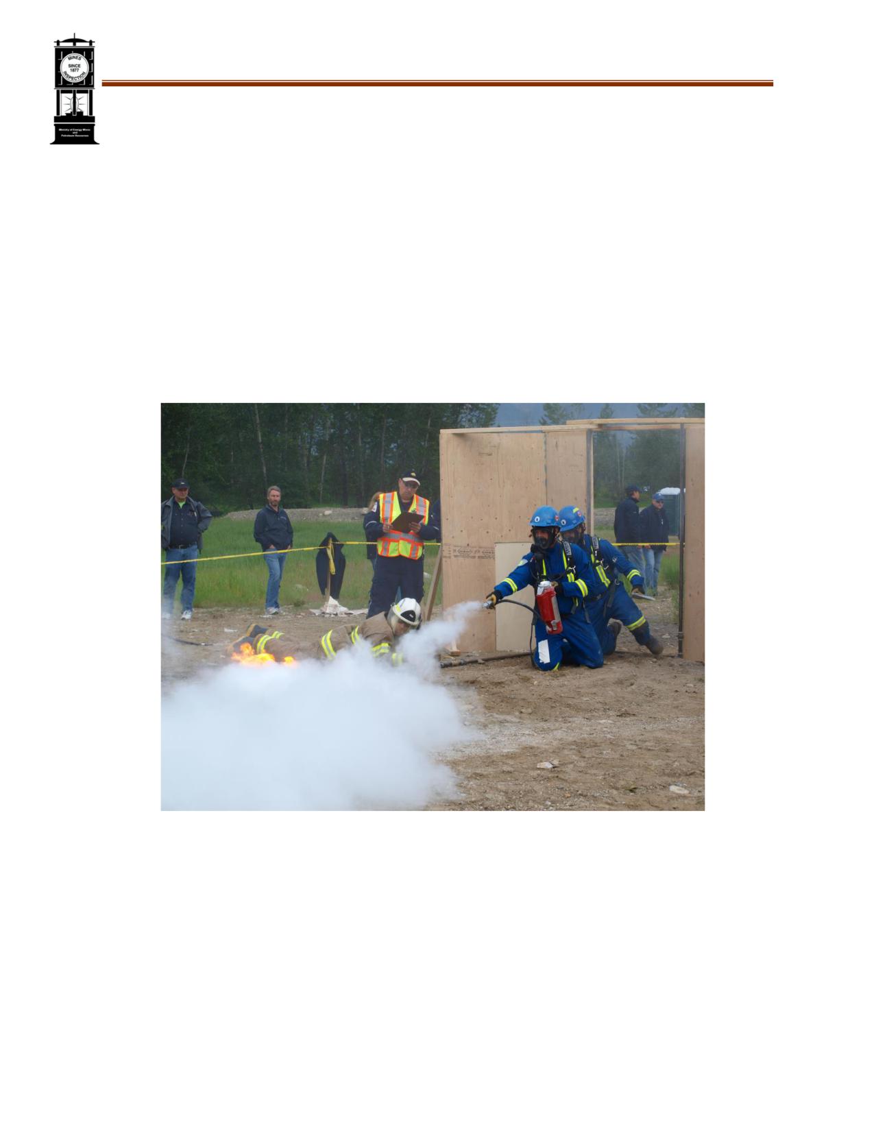
Fire poses major hazards in the rescue and treatment of casualties. Burning structures and equipment
must be addressed efficiently to rescue trapped and injured people, as well as to mitigate damage to
infrastructure. Upon completion of this chapter, the trainee shall be able to demonstrate competency
in:
Components of personal protective equipment used in fire rescue
Fundamental characteristics of fire behaviour
Fire classes, phases, and hazards
Fire extinguisher classifications, types, and agents
Special conditions such as ventilation, equipment fires, and BLEVEs
The information contained within this chapter in no way prepares or certifies the rescuer to
perform interior structural firefighting. Always operate within your scope.
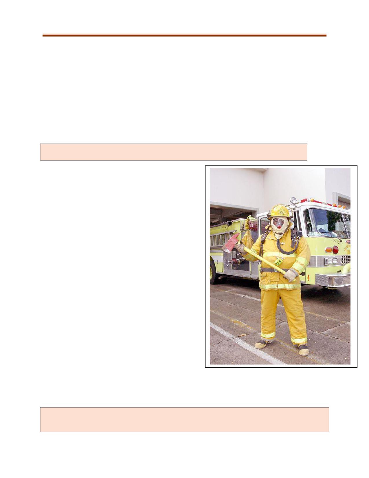
PERSONAL PROTECTIVE EQUIPMENT
Bunker gear (turnout gear) is the protective clothing that
is required to perform fire rescue. This gear needs to be
researched prior to the purchase to ensure that it meets
the current applicable standards and site requirements.
Fire-rated rescue clothing consists of:
Helmet: Protects the head from injury.
Protective Hood (balaclava): Protects parts of the
face that are not covered by the collar or helmet.
Bunker pants and coat: Will protect the body
from heat, cuts, and abrasions.
Gloves: Protect the hands from heat, cuts, and
abrasions.
Bunker boots: Protect the feet from cuts and
abrasions from the top and from the bottom.
Eye protection: Protects the wearer’s eyes from
foreign matter.
Hearing Protection: Protects the ears from
excessive noises.
Respiratory Protection: Protects against heated
gases as well as toxic and oxygen-deficient
atmospheres.
Personal Alert Safety System (PASS): Built into a
breathing apparatus or attached to a rescuer.
Care, Cleaning, and Storage of PPE
Manufacturer’s guidelines must be followed to ensure proper use, storage, and handling.
All equipment used must meet relevant health and safety legislation, standards, and regulations.
During an incident, rescuers may be exposed to biological, chemical, electrical, and fire hazards. Care
should be taken to reduce exposure from contaminated PPE during and after an incident.
10-2
FIRE BEHAVIOUR
Fundamental to a mine rescuer’s safety is a basic grasp of the physics and chemistry of a fire.
States of Matter
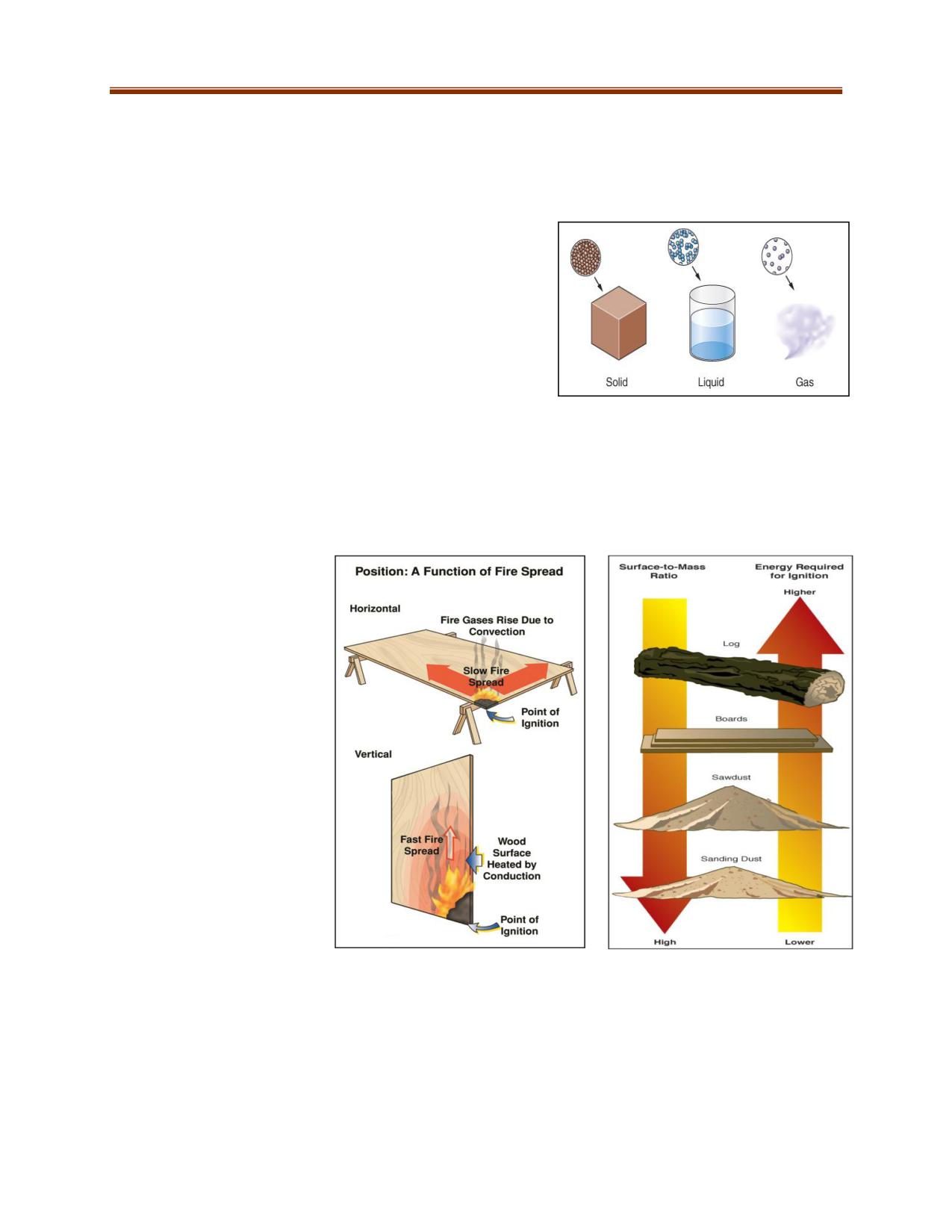
There are three states of matter: solid, liquid, and gas/
vapour.
Two factors that can change the state of matter are heat and
pressure.
When substances are heated, they tend to change from the
solid to the liquid state and then to the gas or vapour state.
When substances are subjected to pressure, they tend to
change from gas or vapour to liquid and then to solid. Materials as a rule will not burn while in their
solid or liquid states. Materials must first change to gas or vapour and then burn.
Factors Affecting Fire Behaviour
Solid fuels have definite size and shape. The surface area of a solid fuel in relation to its mass is a
primary consideration for the mine rescuer. The larger the surface area for a given mass, the more rapid
the heating of the fuel and the process of pyrolysis will be. The physical position of a solid fuel is also
important. If a solid fuel is in
a vertical position, the fire
will spread more rapidly than
if it is in a horizontal position.
Pyrolysis refers to the
decomposition of organic
material at high
temperatures in the absence
of oxygen. During pyrolysis,
the material is heated to a
point that both its physical
state (e.g., solid) and
chemical composition change
at the same time. It usually
produces gases, vapours, and
particulates.
10-3
Liquid Fuels
Liquid fuels have physical properties that increase both the difficulty of extinguishment and the hazards
to personnel. Liquids will assume the shape of their container. When a spill occurs, the liquid will
assume the shape of the ground and will flow and accumulate in low areas. The density of liquids in
relation to water is often referred to as specific gravity (water = 1). Liquids with a specific gravity less
than one are lighter than water. Those with a specific gravity greater than one are heavier than water.
Most flammable liquids have a specific gravity of less than one. Hydrocarbon liquids, as a rule, will not
mix with water.
Gases and Vapours
Gases and vapours tend to assume the shape of their container but have no specific volume. If the
vapour density of a gas or vapour is less than that of air (air = 1), it will rise and tend to dissipate. If a gas
or vapour is heavier than air, it tends to hug the ground.
Fire Triangle
Requirements for Burning
Fire is a chemical reaction known as combustion. It is defined
as the rapid oxidation of combustible material accompanied
by a release of energy in the form of heat and light.
Oxygen
Fuel
Fire Triangle
The three-sided figure of the fire triangle describes the
necessary components to create a fire. When oxygen, heat,
and fuel in proper proportions combine they create a fire. If
any one of the three elements is removed a fire cannot exist.
Heat
Fire Tetrahedron
Some chemicals and materials will
Fire Tetrahedron
ignite and burn in a manner that
cannot be explained completely by the
use of the fire triangle. Some questions
that defy explanation under this
theory are:
Why will calcium and
Heat
aluminium burn in a nitrogen
atmosphere, in the absence of
oxygen?
Uninhibited
Why do some fuels burn more
Chemical
rapidly when subjected to
Chain
Reaction
radioactive emanations (gas)?
Why do flames react with
certain sonic vibrations and
Oxidizing
Reducing
Agent
Agent (Fuel)
electrically charged particles?
10-4
These questions can be answered by using the Fire Tetrahedron. One of the four components serves as
the base and represents the chemical chain reaction. The removal of one or more of the four
components will make this tetrahedron incomplete and result in extinguishment of the fire. This theory
has not done away with the fire triangle. It has simply added a fourth condition.
The four components of the tetrahedron are:
Reducing Agent (Fuel): In the tetrahedron, fuel is defined as “a material that can be oxidized”. The term
“reducing agent” references the fact that fuel reduces an oxidizing agent.
Oxidizing Agent (Oxygen): The term “Oxidizing agent” explains how some materials, such as sodium
nitrate and potassium chlorate (which release their own oxygen under certain conditions), can burn in
an atmosphere free of any outside source of oxygen. For example, zirconium dust can be ignited in
carbon dioxide without oxygen being involved.
Examples of oxidizing agents are:
Oxygen
Nitric Acid
Chlorates
Hydrogen Peroxide
Sulphuric Acid
Chromates
Fluorine
Manganese Dioxide
Nitrates
Chlorine
Lead Dioxide
Bromine
Temperature (Heat): Temperature refers to heat as a quantity of energy. Heat is energy in disorder and
temperature is the measure of the degree of that disorder.
Uninhibited Chemical Chain Reaction: This chain reaction refers to self-sustaining combustion that
continues when heat from the fire radiates back to the fuel, even if the original ignition source is no
longer present.
In the burning of either liquid or solid fuels, the vapours, which are distilled off and carried into the
flame, contain atoms or molecules that have not been consumed in the initial burning process. These
liberated particles may have an electrical charge that either attracts other particles or repels them.
This area, between vapour or gases and the visible flame, is called flame interface. Immediately above
this area, oxygen molecules exist in sufficient number to produce energy reactions, which create light in
the form of flames. This area is fed by the oxygen drawn into the fire as air currents move into the void
created by the rising heated vapours or gases.
This process continues throughout the flame. The molecular structure of the material is broken down,
and the released atoms combine with other radicals and elements which are drawn into the process to
form new compounds, which are again broken down by the heat.
The final by-products then escape the flame in the form of smoke and steam. Since carbon is one of the
elements most difficult to ignite, most of the visible smoke consists of unburned carbon particles. This is
not a step-by-step process. All of the steps occur simultaneously in varying degrees of intensity
throughout the flame.
10-5
Extinguishment
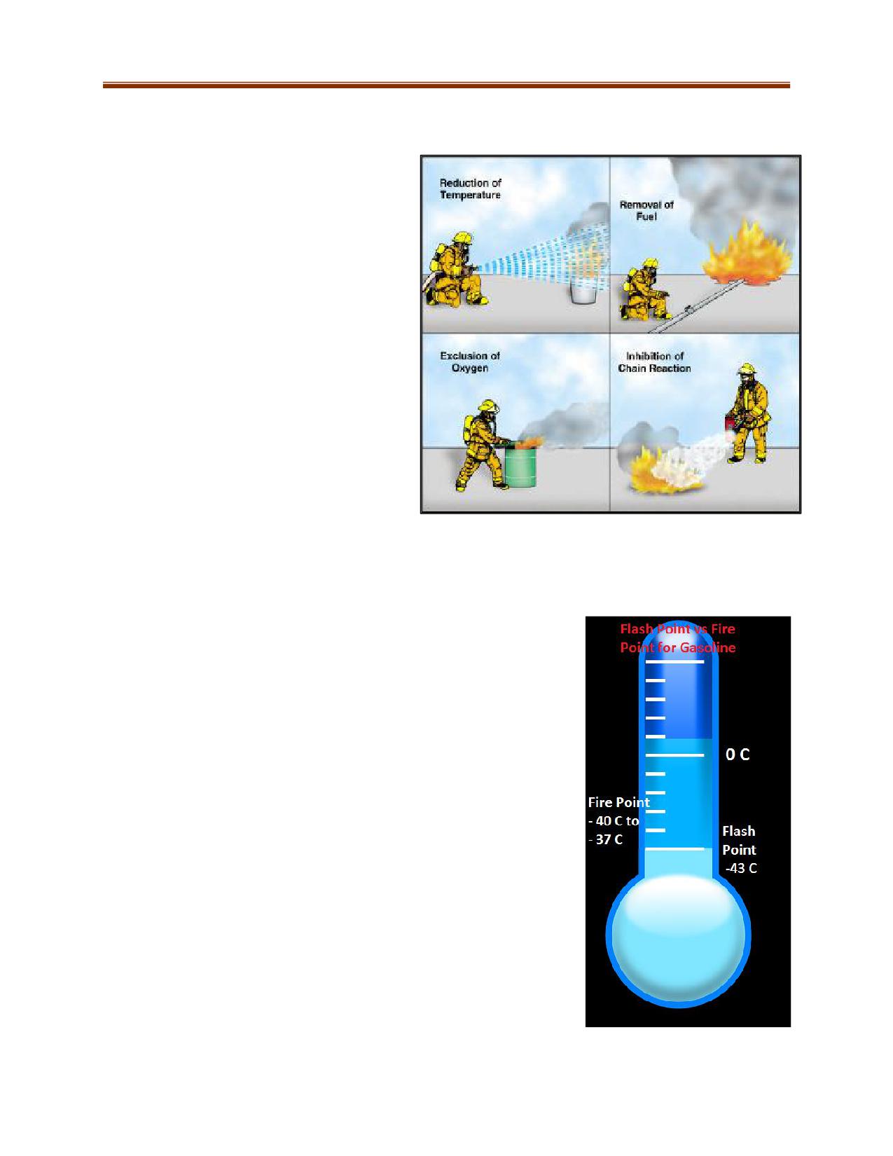
Based on the fire tetrahedron, there are
four methods of fire suppression:
Remove the reducing agent
Exclude the oxidizing agent
Reduce the temperature
Interrupt the chemical chain
reaction
Interrupting the Chemical Chain Reaction
Vapourizing liquid and dry chemical agents
extinguish fire more rapidly than the same
quantity of other smothering agents. When
these extinguishing agents are added to a
fire, they release atoms that combine with
the molecules involved in the chemical
chain reaction. The new molecules formed
by this process do not combine with the
oxygen in the air that keeps the fire
burning, thereby interrupting the chain
reaction.
CONCEPTS AND DEFINITIONS
Ignition Temperatures
Auto-ignition Temperature is the temperature at which a material will
ignite spontaneously, independent of an external ignition source.
Flash Point is the lowest temperature at which fuel will give off enough
vapours to ignite when exposed to an external ignition source.
Fire Point is the temperature at which a liquid fuel will produce
vapours sufficient to support combustion once ignited. The fire point is
usually a few degrees above the flash point.
Ignition Temperature refers to the minimum temperature to which the
material must be heated to initiate self-sustained combustion
independent of an outside heating source.
10-6
Sources of Ignition
Adiabatic compression involves compressing a liquid or gas to produce heat. This heat is generated by
molecules running into one another and against the sides of the container. A flammable substance
compressed quickly enough can raise the temperature to the substance’s ignition point.
Spontaneous heating occurs when the temperature of a given substance rises without any external heat
source present. Heat is given off by oxidation, but in most circumstances it dissipates harmlessly.
However, if three conditions are present, spontaneous heating can lead to ignition:
The material in question insulates more heat than is being dissipated
Heat production is great enough to reach the ignition temperature
Enough air is present to support combustion
Examples of such circumstances are bunched-up oily rags and charcoal piles.
Hypergolic mixtures are normally fuels used to propel missiles or rockets. These liquids are designed to
ignite once in contact with another hypergolic mixture and do not require an external ignition source.
Friction sparks are created when two hard surfaces touch one another with sufficient force. One of the
surfaces is usually metal. These sparks can ignite any flammable gases and vapours present.
Sources of Heat
As the temperature of a substance rises, the motion of the molecules increases and becomes more
rapid. Heat, as energy, is a measure of molecular motion in a material. Because molecules are constantly
moving, all matter contains some heat regardless of how low the temperature is. The speed of the
molecules increases when a body of matter is heated. Anything that sets the molecules of a substance in
motion produces heat in that material. The sources of heat energy generally encountered in mine rescue
are:
Chemical heat energy
Electrical heat energy
Mechanical heat energy
Chemical heat energy is generated when combustible material absorbs heat from a source of ignition. It
is the most common source of heat energy in combustion.
Electrical energy can lead to combustion by releasing heat through arcing, induction, or resistance to
the flow of an electrical current. Static electricity can also produce a spark that is capable of igniting
flammable vapours and gases.
Mechanical heat energy is produced by either compression or friction. Two materials moving against
one another create friction, which releases heat and/or sparks. Compression creates heat when
pressurizing gas in a container.
10-7
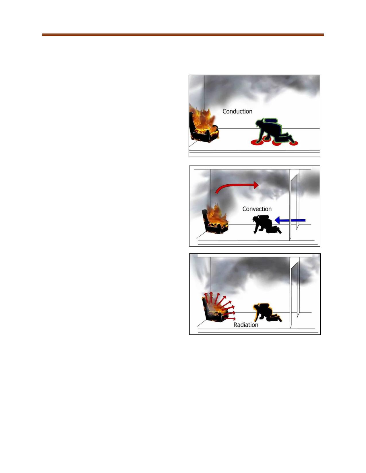
Transmission of Heat
Heat can travel throughout a burning building by one or more of three methods: conduction,
convection, and radiation. Heat tends to move from a hot substance to a cold substance.
Conduction involves transfer of heat from one
body to another by direct contact or by an
intervening heat-conduction medium. Speed of
transfer is dependent on the conductivity of the
material.
Good heat conductors include copper, aluminum,
and iron. Poor heat conductors include masonry,
wood, fibrous materials, and air, liquids, and
gases.
Convection is the transfer of heat by the movement
of air or liquid. When liquids and gases are heated
they begin to move within themselves. As heated
air expands and rises, cooler air takes its place at
the lower levels. Convection heat currents are
generally the cause of heat movement from floor to
floor, from room to room, and from area to area.
The spread of fire by convection influences the
positions for fire attack and ventilation more than
any other method of heat transmission.
Radiation is the transmission of energy as an
electromagnetic wave without an intervening
medium. Heat waves (infrared rays) are similar to
light waves in nature but they differ in length and
energy. As an object is exposed to radiant heat
waves, it will absorb or reflect the heat depending
on its properties.
Radiated heat is one of the major sources of fire
spread and its importance demands an immediate
defensive attack at points where radiation exposure
is severe.
Products of Combustion
When a fuel burns there are three products of combustion:
1. Thermal Energy is released as heat and flame.
2. Smoke (Particulate) is solid matter made up of unburned, partially, and completely burned
substances.
3. Toxic Smoke (fire gases) is made up of the various gases produced during the combustion
process. A few examples are carbon monoxide, hydrogen cyanide, and chlorine.
10-8
CLASSIFICATION OF FIRES
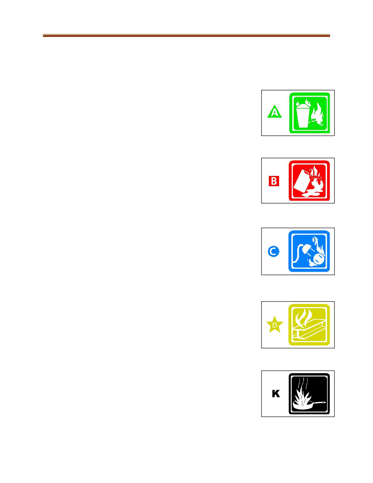
Fires are classified into five categories of fire based on important properties, such as the materials
combusting and the means of extinguishment. Identifying the correct class of fire is integral to any fire-
fighting response.
Class “A” - Fires involve ordinary combustible materials, such as paper, wood,
and cloth. These fires require a cooling, blanketing, or wetting extinguishing
agent such as water or multi-purpose dry chemical.
Class “B” - Fires involve flammable liquids such as gasoline, kerosene and
greases. Extinguishing agents for this type of fire include carbon dioxide, dry
chemical and foam that can interrupt the chemical chain reaction, exclude
oxygen, and inhibit the release of combustible vapours.
Class “C” - Fires involve energized electrical equipment. A typical
extinguishing agent is carbon dioxide. High value areas are protected with
“clean agents” that leave no residue on electrical equipment. If the
electricity can be de-energized (turned off), the underlying fuel is often class
A or B.
Class “D” - Fires involve combustible metals such as magnesium, potassium,
lithium, titanium, and aluminum. Special dry powder extinguishing agents are
required for this class of fire, and must be designed for the specific hazardous
metal. If not available, dry sand can be used. Do not use water.
Class “K” - Fires involve commercial kitchen appliances with vegetable oils,
animal oils, or fats at high temperatures. A wet potassium acetate, low pH-
based extinguishing agent is used for this class of fire.
10-9
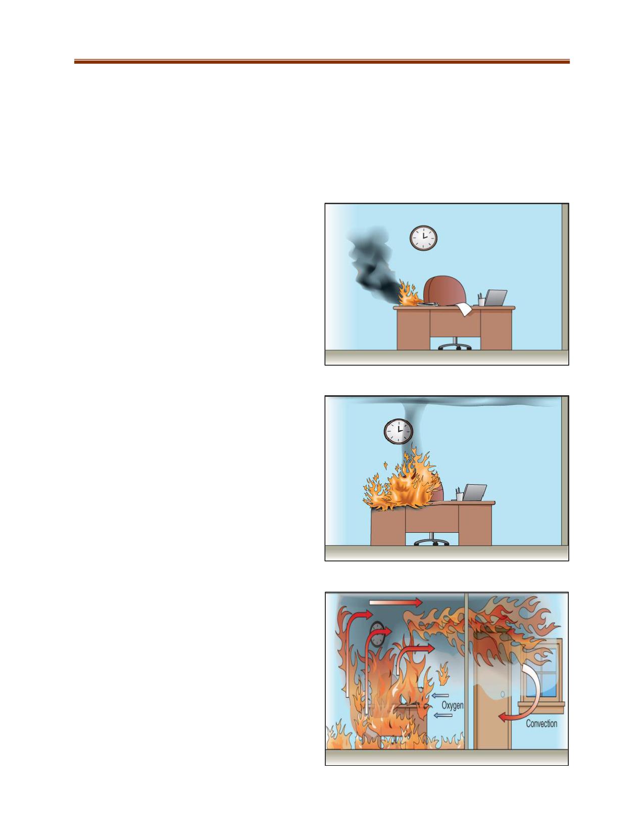
PHASES OF FIRE
When fire is confined to a building or room, a situation develops that requires carefully calculated and
executed ventilation procedure to prevent further damage and reduce danger. This type of fire can be
best understood by an investigation of its four progressive phases:
Incipient
Growth
Fully Developed
Decay
Incipient (Ignition) Phase
The incipient phase starts when the elements of
the fire tetrahedron come together and
combustion begins. The oxygen content in the
air has not been significantly reduced and the
fire is producing some gases. The temperature in
the room during this phase will only be slightly
increased.
Growth Phase
During the growth phase, oxygen-rich air is
drawn into the flame as convection (the rise of
heated gases) carries the heat to the uppermost
regions of the confinement area. The heated
gases spread out laterally from the top
downward, forcing the cooler air to seek lower
levels and eventually igniting all the combustible
material in the upper levels of the room. This
process is known as thermal layering. Additional
fuel is ignited and the fire grows in size.
Flashover can occur spontaneously and rapidly
with a release of dangerous amounts of heat
and into the next phase of the fire.
Fully Developed Phase
During the fully developed phase, oxygen is
consumed rapidly and the heat produced is at
its maximum. All combustible materials in the
compartment are burning and producing large
volumes of fire gases. The fire will continue to
burn as long as fuel and oxygen remain.
10-10
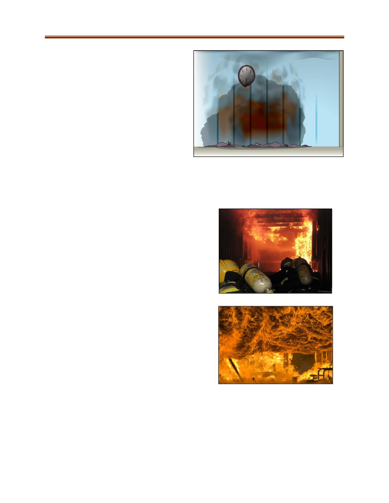
Decay Phase
In the decay phase, flame may cease to exist
and the fuel and/or oxygen are nearly
exhausted. Burning is reduced to glowing
embers. The fire will continue to smoulder
and the room will completely fill with dense
smoke and gases of combustion. Eventually
the fire will go out.
HAZARDS OF FIRE DEVELOPMENT
Rollover occurs when unburned combustible gases that
were released during the ignition or growth phase of a fire
accumulate at the ceiling. When they mix with oxygen and
reach their flammable range, they ignite and a fire front
(licks of flame igniting in upper layers of smoke) develops,
expanding very rapidly and rolling across the ceiling.
Flashover is the transition from the growth phase
to the fully developed phase of a fire. It occurs
when the surfaces and contents involved in the
fire have been heated and gases given off by
pyrolysis have ignited. Flame breaks out almost at
once over the surface of the contents involved in
the space.
Signs of flashover are:
Dense black smoke
Fire gases begin to fill the fire area
Rollover is visible
10-11
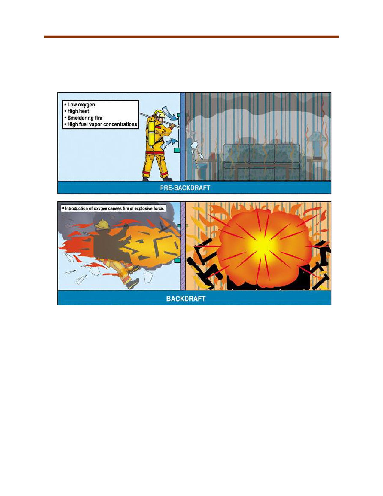
Backdraft usually occurs during the decay phase when a fire is smouldering. If there is insufficient
oxygen, the unburned gases may collect in pockets throughout the structure or fill the entire building.
Such a condition needs only the admission of sufficient fresh air (oxygen) to cause a very rapid burning
of these gases, the expansion of which may be sufficient to cause an explosion.
The degree of intensity of the back draft depends upon the degree of confinement, the amount of
heated gases, and the rate and volume of fresh air (oxygen) admitted. This type of condition can be
made less dangerous by proper ventilation.
Signs of impending backdraft:
Little or no visible flame
Smoke emanating under pressure from cracks, i.e., around windows or doors
Smoke may be drawn back in
Smoke is exiting in puffs or intervals
Black smoke becoming dense grey yellow
Smoke-stained or blackened windows
10-12
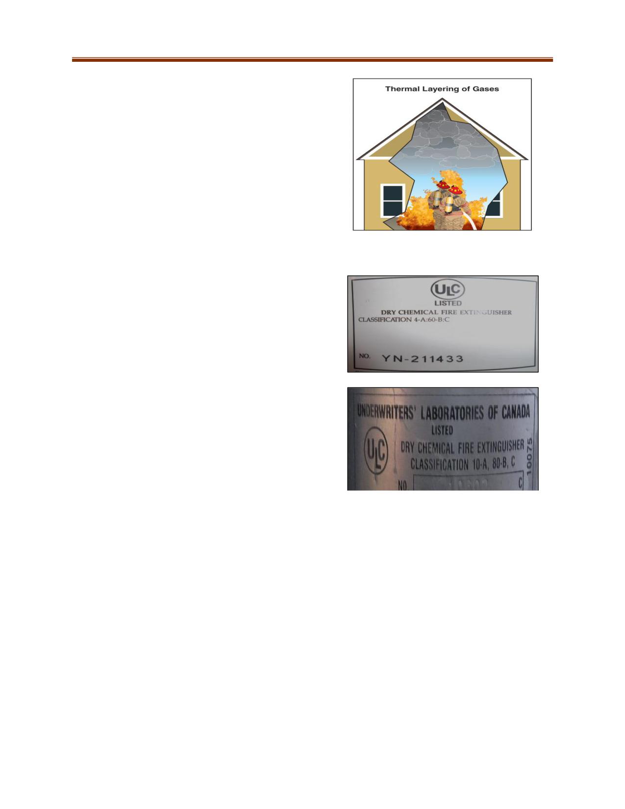
Thermal Layering is caused by convection and is the
tendency for gases to form into layers according to their
temperatures. It is also known as heat stratification or
heat balance. The hottest gases tend to accumulate at
upper levels, a phenomenon known as mushrooming.
Cooler gases accumulate at lower levels. Thermal layering
is disrupted when water is applied directly into the layer
without proper ventilation. This results in steam, smoke,
higher temperatures and decreased visibility at the lower
level which are detrimental to a rescuer.
FIRE EXTINGUISHERS
Fire Extinguisher Classification
Fire extinguisher classification is based on physical fire
extinguishing potential. Extinguishers are designated as
Class “A”, Class “B”, Class “C”, Class “D”, and Class “K”,
with some types having a dual or triple classification.
The classification consists of a number and a letter. It
appears on the label affixed to the appliance by the
Underwriters’ Laboratories of Canada (ULC) or another
recognized agency.
The numeral indicates the approximate relative fire
extinguishing potential of the extinguisher. In addition,
it is an approximation of the number of square feet
(1ft² = 0.09 m²) of appreciable depth flammable liquid
that may be extinguished. Appreciable depth is defined
as a depth of liquid greater than ¼ inch (6 mm).
The letter refers to the class of fire.
The number indicates “units” of fire extinguishing potential and does not refer to the size, capacity or
quantity of extinguishing agent used. These ratings are based on an untrained operator. An expert can
be expected to extinguish up to 2.5 times as much fire as a novice with the same quantity of agent.
1A = agent contained is equivalent to 1.25 U.S. gallons (4.7 L) of water
B = rated to extinguish the square footage of Class B fire
C = non-conductive agent
Examples:
4A 60B C = agent contained is equivalent to 5 U.S. gallons (18.8 L) of water, rated to extinguish
60 ft² (5.6 m2) of Class B fire. Agent is non-conductive.
10A 80B C = agent contained is equivalent to 12.5 U.S. gallons (47 L) of water, rated to
extinguish 80 ft2 (7.4 m2) of a Class B fire. Agent is non-conductive.
10-13
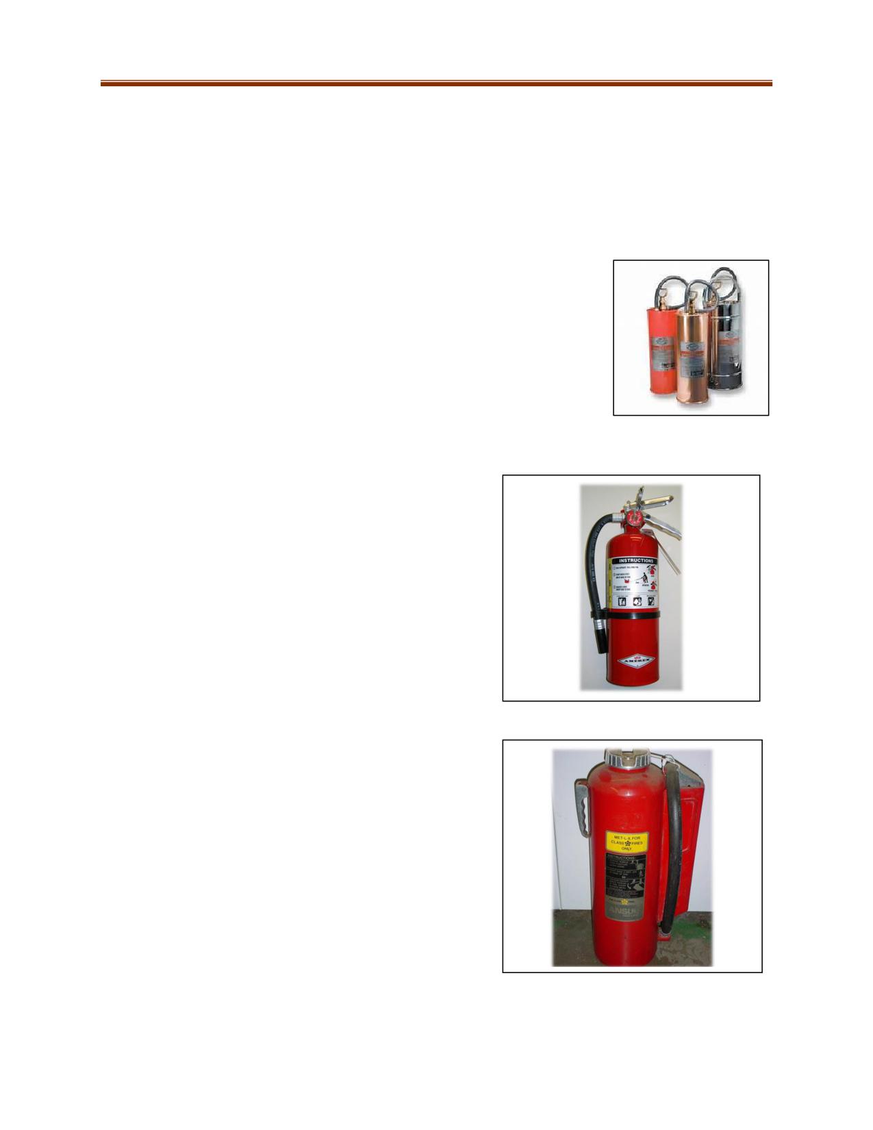
Types of Fire Extinguishers
Note: Operating instructions must be clearly understood. Extinguishers must be fully charged, in their
designated place, and ready for use.
Hand-Operated Pump
Normally used for water-type agents only. It has a built-in hand-operated double-action pump that
discharges water on a continuous up/down or in/out stroke. These extinguishers are normally rated
Class “A” only.
Stored pressure
The expellant and the extinguishing agent are stored within a single cylindrical container. The
extinguisher will include:
Pressure gauge
Carrying handle
Discharge lever with pin/tamper seal
May or may not have a hose
This type of extinguisher can contain most agents including:
Water
AFFF
Dry powder
Dry chemical (including multipurpose)
These extinguishers may be rated for a combination of Class
“A”, “B” and/or “C” fires as well as Class “D”. Check the label.
Gas Cartridge
The expellant is contained in a separate cartridge. This
cartridge is normally attached to the outside of the cylinder
but it can also be found inside with the agent. This type of
extinguisher primarily contains:
Dry powder
Dry chemical (including multipurpose)
These extinguishers can be rated for Class “A”, “B”, “C”, “D”
fires, or a combination thereof.
10-14
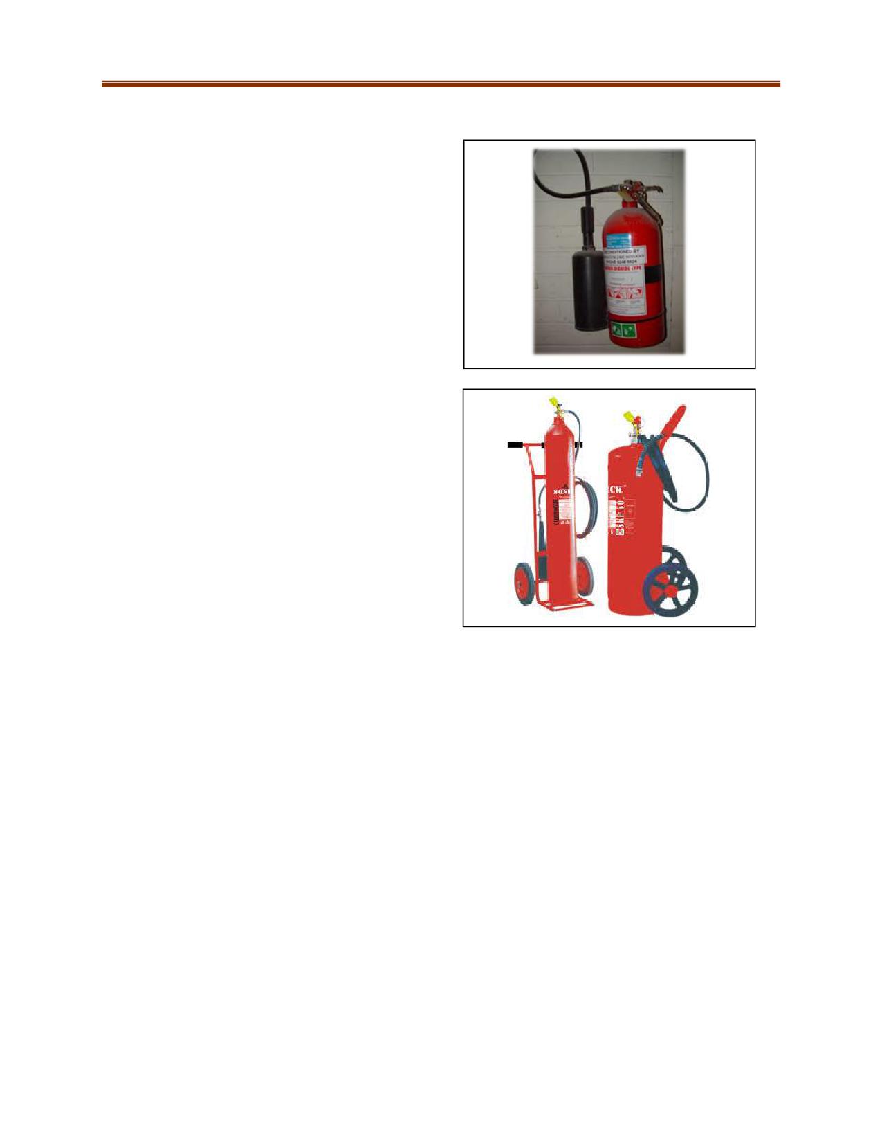
Self-Expellant
In this type the expellant is the extinguishing agent.
The agent has enough vapour pressure to expel
themselves when the extinguisher is activated. These
extinguishers can be rated for Class “A”, “B”, “C”, “D”
fires, or a combination thereof.
Large Wheeled and Stationary Units
These units are located by fire protection specialists
to cover specific risks in most cases, such as fuel and
lube stations. These extinguishers can be rated for
Class “A”, “B”, “C”, “D” fires, or a combination
thereof.
10-15

Extinguishing Agents
Mine rescuers must be familiar with the different extinguishing agents available and the corresponding
classes of fire.
Extinguishing
Classes
Advantages
Limitations
Agent
Water
A
Non-toxic, plentiful, efficient
Generally safe for only
Converts from liquid to steam,
Class A fires
absorbing heat in the process
Electrically conductive
Can be pressurized
Good range and penetration
Absorbs more heat per volume
than any other agent
Carbon Dioxide
B, C
Does not leave a residue
Limited range
Non-freezing
Affected by the wind
Can be hazardous if used
in a confined or
unventilated space
Cold shock to electrical
equipment
Dry Chemical
B, C
Non-freezing
Leaves a residue
(standard ordinary
Can be used with water stream or
Can be corrosive
base)
fog
Limited range
Can be used in the wind
Limited cooling effect
Multi-Purpose Dry
A, B, C
Non-freezing
Leaves a residue
Chemical
Limited range
Limited cooling effect
Foam
A, B
Class A foam has excellent wetting
Leaves a residue
(Two classes: Class
and penetrating properties due to
Will freeze
A and B)
low surface tension
Requires selection of
Class B foam can make water float
correct foam for the fire
on fuels that are lighter than water
application
Class A/B create a vapour seal on
fuels
Dry Powder
D
Specific agents used for Class D
Incorrect application can
fires
spread the fire
Not widely available
Specific to only one type
of metal
Wet Agents
K
Saponification turns oils and fats
Only rated for Class K
into soap/foam
fires
Creates thick blanket to smother
the fire
Effective, easy to clean up
10-16
Portable Fire Extinguishers
The basic components of portable fire extinguishers are:
Cylinder or Container: Holds the extinguishing agent. Some extinguishers also contain expellant,
which can be stored internally (stored pressure) or externally (cartridge type).
Handle: Used to carry an extinguisher and to be held during use.
Nozzle/Horn: Expels agent. Attached to the valve assembly or at the end of a hose.
Activation Mechanisms: Discharges agent when activated.
Locking Mechanism/Tamper Seal/Pin: Prevents accidental discharge.
Pressure Indicator: On stored-pressure extinguishers, the gauge shows pressure of extinguishing
agent stored. Some cartridge extinguishers have a pin that indicates whether it has been
pressurized. Other extinguishers may not have any indicator.
Label: Indicates classification, agent, as well as maintenance and use instructions.
VENTILATION
Ventilation is an important firefighting tactic that involves the expulsion of heat, gases, and smoke from
a fire building, permitting the mine rescuers to safely find trapped individuals and attack the fire. If not
properly ventilated (e.g., poorly timed or located), a fire can:
Be much harder to control
Produce enough heat to create a flashover
Result in conditions conducive to backdrafts
Increase the fire’s air supply, causing it to grow and spread rapidly.
Natural
Open doors/windows, wind, etc.
Can be vertical or horizontal
Mechanical
Positive Pressure Ventilation (PPV) - PPV
Negative Pressure Ventilation (NPV) -
fans
Smoke ejectors
Hydraulic
Water fog spray - Nozzle at 60 degree fog pattern covering 90% of an opening
Advantages of ventilation
Aids life-saving and rescue
Speeds attack and extinguishment
Controls fire spread
Reduces danger of backdraft
Reduces mushrooming
Reduces hazard to rescuers
Permits prompt salvage operations by reducing smoke, heat, water, and fire damage
Considerations for Safely Performing Ventilation
Location, duration, and extent of fire
Need, type, and location of ventilation
The age and type of structure involved
Whether ventilation can be performed
safely
Escape routes for rescuers and casualties
Trained personnel, tools, and equipment
available
10-17
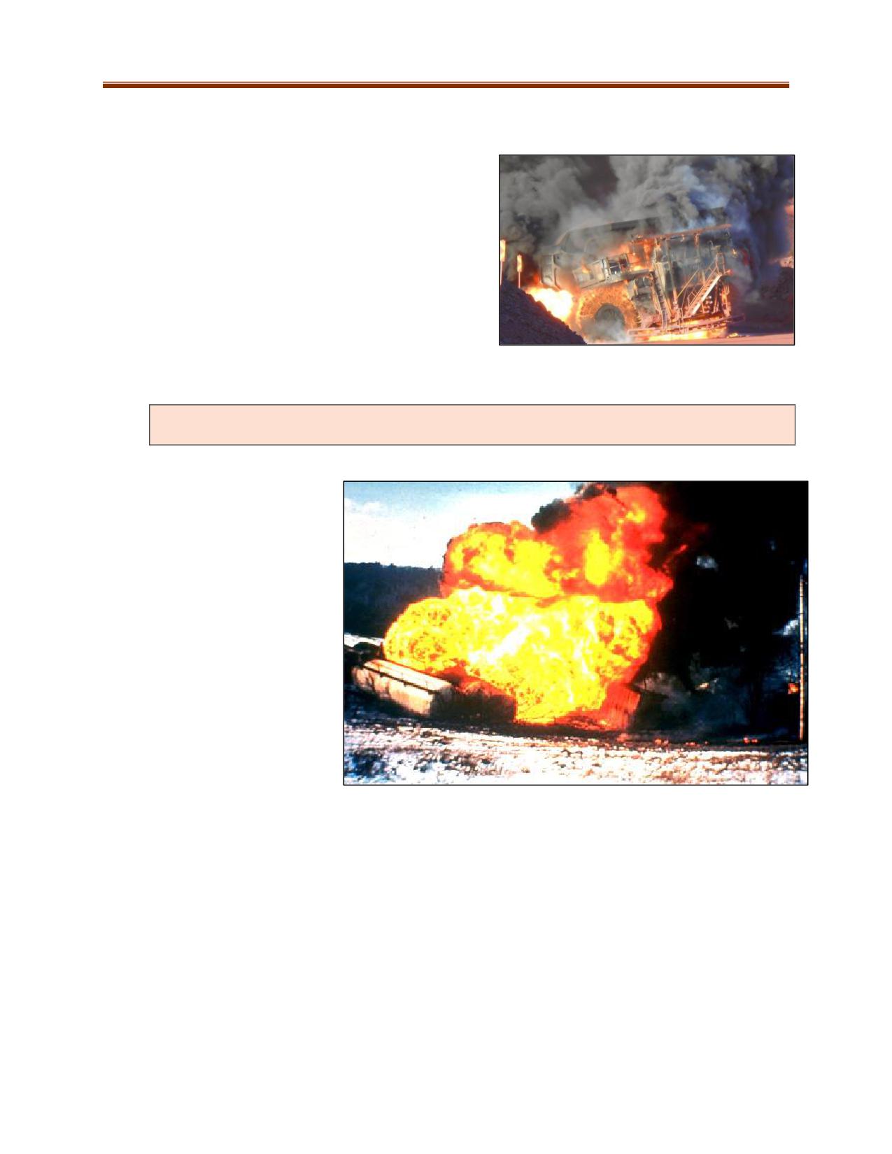
EQUIPMENT FIRES
Mine rescuers should not attempt to fight equipment
fires unless they can do so competently and have the
necessary equipment. Mine rescuers must be aware of
the numerous hazards present in equipment fires. These
include but are not limited to:
Fuel and lubricant volumes
Batteries and electrical
Stored energies, e.g., hydraulic components,
airbags, and tires
Unidentified cargo
BLEVE (BOILING LIQUID EXPANDING VAPOUR EXPLOSION)
The information contained within this section in no way prepares the rescuer to
actively respond to potential BLEVEs. Always operate within your scope.
A confined gas or liquid is
potentially dangerous, regardless
of whether the content is
flammable. BLEVEs can be caused
by a fire near or impinging the
storage vessel, heating the
contents and increasing the
pressure inside.
Storage vessels are designed to
withstand the stored pressure,
but impinging flame can cause the
metal to weaken and eventually
fail. If the storage vessel is being
heated in an area where there is
no liquid, it may rupture faster
without the liquid to absorb the
heat.
Pressurized vessels are equipped with relief valves that vent off excess pressure, but the vessel can still
fail if the pressure is not released quickly enough. Relief valves are sized to release pressure fast enough
to prevent the pressure from increasing beyond the strength of the vessel, but not so fast as to be the
cause of an explosion. An appropriately sized relief valve will allow the liquid inside to boil slowly,
maintaining a constant pressure in the vessel until all the liquid has boiled and the vessel empties. If the
substance being stored is flammable, once the vessel fails the liquid immediately turns into a rapidly
expanding cloud of vapour that ignites into a huge fireball. Mine rescuers must keep in mind that a
BLEVE can send solid projectiles flying for great distances.
10-18

Western Canada Mine Rescue Manual
Chapter 11 Rope Rescue
11-2
OBJECTIVES
The primary objective of mine rescue work is the safe recovery of casualties, often from dangerous and
inaccessible places. This will frequently require the use of ropes and harnesses to allow mine rescue
workers to reach the injured and to raise or lower them to safety. Upon completion of this chapter, the
trainee shall be able to demonstrate competency in:
Rope rescue personal protection equipment
Key concepts and definitions
Ropes, webbing, hardware, and related equipment, and their uses in rescue work
How to tie a number of knots, bends and hitches used in rescue work
How to prepare rescue harnesses and secure a patient to a rescue stretcher
How to set up a safe anchor system
How to build mechanical advantages
How to build safety belays and the radium release hitch
Introduction
The basic goal of any rescue recovery operation is to remove the casualty from his or her predicament
as quickly as possible with maximum safety provided to both the rescue team and the casualty.
Rope rescue is a dangerous activity. Safety must be stressed at all times, such as when selecting
equipment, techniques, and personnel.
Technical rescue is a hazardous activity. Risk management is a result of experience, training, and
good personal judgement. The skills and techniques shown in this chapter are for expert use only. It
is your responsibility to seek competent, hands-on instruction as well as to obtain quality equipment
and to follow safety procedures.
11-3
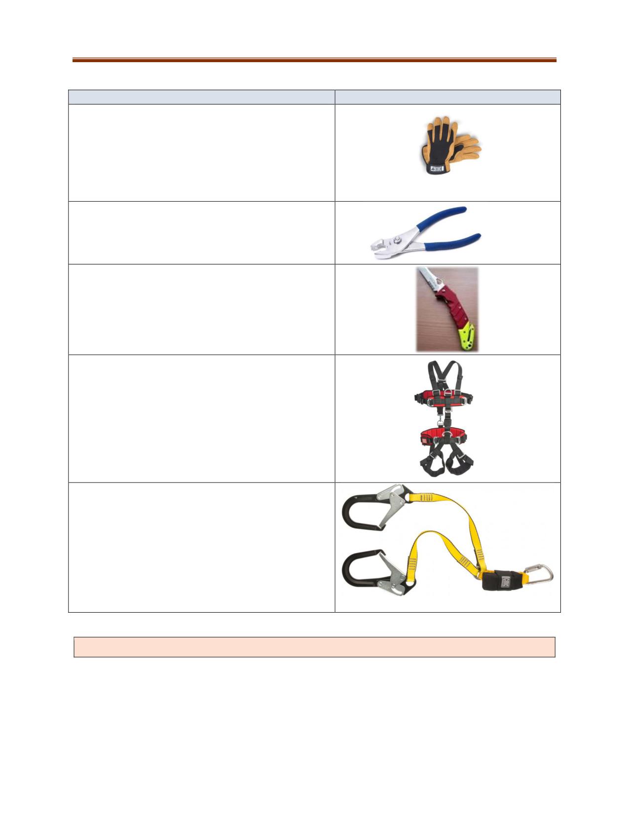
PERSONAL PROTECTION EQUIPMENT
Equipment
Photo
Gloves: All rescuers handling a moving rope must wear
protective gloves. These will provide protection from
rope burns and to some degree from pinch points.
They should be snug for dexterity and increased
gripping ability. Only use gloves made of leather or
with thick synthetic palms to resist abrasion.
Pliers: Used to free a jammed carabiner.
Knife or Suitable Cutting Tool: Used to cut open
jammed systems. Must be kept sharp.
Rescue Harnesses: Must be commercially
manufactured, NFPA certified Class III. The harness
style needs to have the capability of providing two
separate frontal tie-in points, one at the chest level for
belay attachment and one at the waist level for front
load-bearing attachment. A third dorsal D attachment
point for fall arrest is also required.
Lanyard: Used as an attachment between the rescue
harness and secure anchor point. Must meet minimum
relevant health and safety legislation of jurisdiction.
All safety precautions must be in place before freeing a jammed system by cutting.
11-4

ROPE AND WEBBING
Rope Design and Construction
Rope is used for rescue or recovery work and climbing. Being able to use rope properly is important in
both underground and surface mine rescue. Bringing an injured patient out of a stope is no different
from raising an accident casualty up over a bench in an open pit mine or over a natural obstacle on the
surface.
Synthetic Rope
Synthetic ropes have replaced natural ropes for mine rescue work. Synthetics are resistant to mildew
and rot, and stronger for equivalent diameters. They are resistant to abrasions and easy to handle.
Kernmantle
Kernmantle rope is rope that is not twisted. Instead, the “kern”
or interior core is made of units of nylon fibers. The mantle is
then woven around the outside of the nylon fibers.
Most rope rescue operations use nylon kernmantle ropes. The
nylon core supports as much as 90% of the load’s mass, while
the mantle protects the rope. Some kernmantle ropes have a
coating on top of the mantle that is designed to protect the rope
from water, cuts, and other damage. However, the coatings
make ropes slippery and therefore unsuitable for rope rescue.
Low-Stretch Ropes (Static Kernmantle - Rescue):
Kernmantle rope
Strongest of the common rope types
Thicker sheath, more abrasion resistant
Tend to be stiffer than climbing ropes
Stretches approximately 3-5% with a one-person load or 2% with a 200-lb. load
High-Stretch Ropes (Dynamic Kernmantle - Climbing):
Not suitable for rescue operations except where single-person climbing is required
The mantle is thinner than static ropes, susceptible to abrasion and dirt
Stretches approximately 5-9% with a 200-lb. load
Designed for single person load
The high stretch absorbs shock in cases such as a falling lead climber (climbing above anchor
points). Lead climbing is beyond the scope of this training manual and program. Site specific
training must be provided to rescue personnel who may be required to climb.
Rope Attributes
Tensile Strength is the ability to withstand force that is applied slowly to the point of failure, e.g., with a
weight suspended from a rope.
Breaking Strength is the amount of force required to break the rope with a straight pull, such as in a tug-
of-war where the amount of pull gradually increases.
11-5
Safe Working Load, or load capacity, is the weight or force that can safely be applied to a rope. The
maximum safe working load is a percentage of the breaking strength.
Safety Factor is the ratio of the rope's breaking strength to its maximum safe working load. The safety
factor is meant to account for wear and tear and reduction of integrity under operating conditions.
Do not consider the safety factor of a rope as reserve strength to be used for additional capacity.
Safe Working Load
The safe working load (SWL) for rope uses a factor of ten as a safety margin. It can be calculated by
using this formula:
SWL = MBS ÷ 10
where SWL is the Safe Working Load and MBS is the minimum breaking strength
Consult your specific rope manufacturer for breaking strength. At a minimum, ropes used in rescue
work should meet the guideline in NFPA 1983 for “General Use”. The ropes must also maintain a 10:1
safety factor.
Force: Something that causes or restrains motion. The formula for calculating force is:
F = M(A)
where F is Force, M is Mass, and A is Acceleration.
A Newton (N) is the measurement used to represent the amount of force needed to move one kilogram
of mass at the rate of one meter per second squared (1N = 1 kg m/s²). The most commonly used unit of
measurement for the forces encountered in rope rescue is the kilonewton (kN, 1 kN = 1,000 N).
Classification
Rope Diameter
Rated Load
Rated Load
Minimum Breaking Strength
(Persons)
(Weight)
Personal
19/64” (7.5 mm)-
One
300 lb (136 kg)
3,034 lbf (13.5 kN)
Escape Rope
3/8” (9.5 mm)
Light-use Life
3/8” (9.5 mm)-1/2”
One
300 lb (136 kg)
4,496 lbf (20 kN)
Safety Rope
(12.7 mm)
General-use
1/2” (12.7 mm)-
Two
600 lb (272 kg)
8,892 lbf (40 kN)
Life Safety
5/8” (16 mm)
Rope
Source: NFPA 1983, Standard on Life Safety Rope and Equipment for Emergency Services
Always check the manufacturer’s specifications to determine the strength of the rope being used.
11-6
Caring for Rescue Ropes
Inspection
Inspect new ropes prior to service and after every use
Examine for damage:
o History of impact by an object
o Melting
o Flattened or soft spots that cannot be worked back into shape
o Bulges and other irregularities
o Cuts or core showing through the outer sheath
o Extreme sheath slippage
o Discolouration or any other signs of exposure to contamination
Usage
Avoid stepping on ropes.
Protect from falling objects such as rocks.
Avoid dirt or grit that may work into the core and cause damage not immediately visible.
Do not let moving ropes cross against stationary ropes or webbing as friction can cause melting.
Use edge protection to prevent abrasions.
Avoid twisting or kinking.
Use pulley blocks that are four times the width of the rope being used.
Do not smoke around ropes and rigging equipment during rescue operations.
Storage
Protect from exposure to chemicals, high temperatures, and direct sunlight
Dry, coil, or bag properly after each use
Maintain an inventory and rope service log for each rope in use
Cleaning
Wash ropes with a rope washer or by hand with a brush
Ropes can also be cleaned in a washing machine but only if they are properly chained and the
washing product is suitable.
Retirement
Retire rope if it does not pass inspection or after it has been in service for five years.
Retire rope if experiencing high sheath abrasion, i.e., if more than 50% of the rope appears
worn, or 30% of the fibres of the webbing are worn.
Once retired, cut rope into small pieces so that they cannot be used.
Cordage
There are two basic classes of cordage, each with their own special uses: Prusik and Accessory Cord.
Prusik Rope is designed to be flexible enough to grip rope. A rescuer should be able to squeeze cordage
together between two fingers.
Used for self-rescue, rope grabs, belaying, and release hitches.
Prusik rope is 8-9 mm in diameter when used for rope rescue systems and must be a minimum
of 2 mm smaller than the rope it is being tied to.
11-7
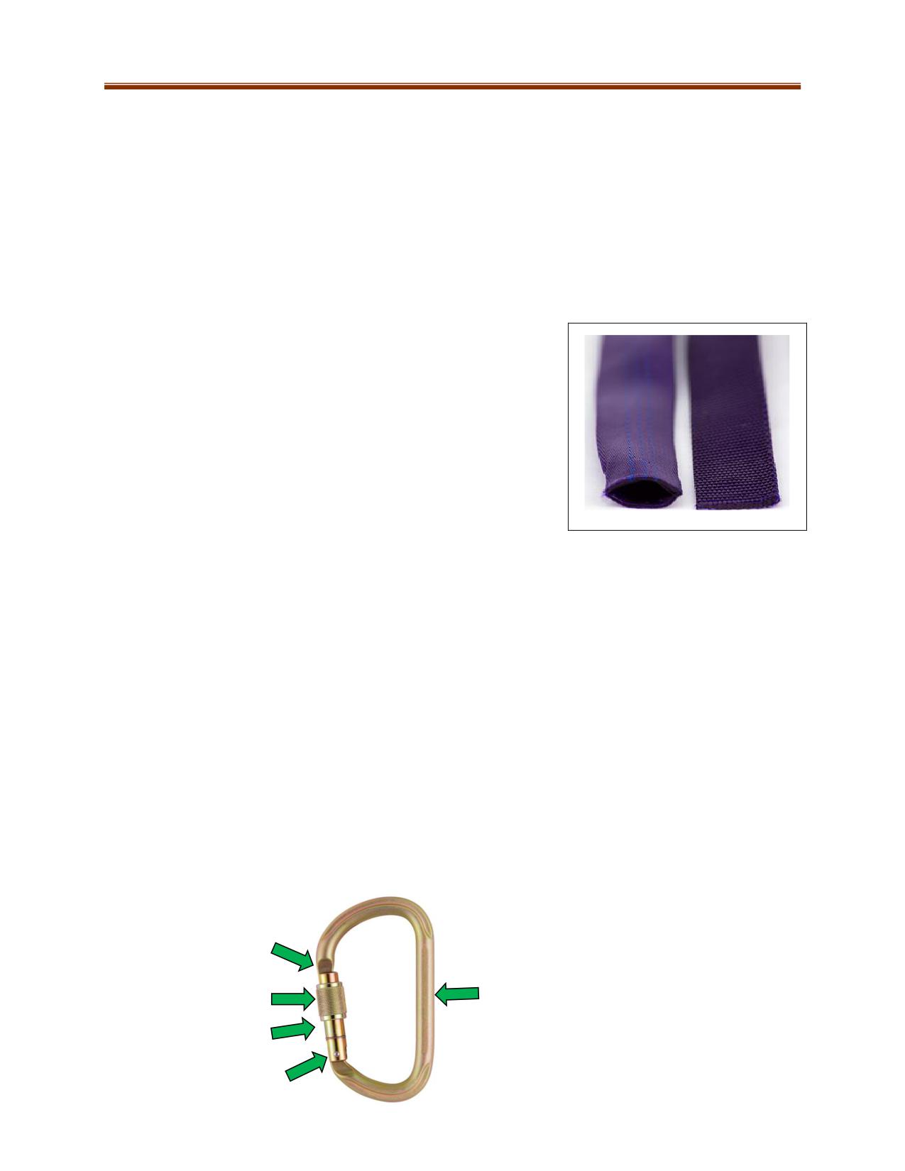
Accessory Cord is any narrow diameter rope made from nylon, polyester, Spectra, Kevlar or combination
thereof.
Not pliable enough to be used for prusiks.
Accessory cord used for radium load release hitches and other applications in technical rope
rescue is 100% nylon with a diameter of 8-9 mm.
Webbing
Webbing is primarily used for harnesses and slings. It can be best described as flat rope. Flat Webbing is
constructed of a single layer of materials, just like seat belt webbing. Tubular Webbing is used in high-
angle environments because it is more flexible. You can recognize tubular webbing because it is hollow
and forms a tube when two ends are squeezed inward. Tubular
webbing is:
Sometimes preferable to rope
Constructed of nylon or polyester
More comfortable than rope against the body for
harnesses
Has a wide, flat surface so it can be more abrasion resistant
in many rigging applications
L-R: Tubular, Flat
HARDWARE
Rescue teams use a number of pieces of hardware in their operations, including carabiners, brake bars,
descending equipment, pulleys, steel O rings, anchor plates, tri-links, stretchers, and more. Proper use
and care of the core pieces of hardware is described below.
Carabiners are metal connectors that link the elements of a rescue system. The basic parts of a
carabiner include the spine, hinge, lock, gate, and latch. Carabiners used in rope rescue:
Must be inspected before and after every use
Must be tested as per manufacturer's specifications
Basic Carabiner Shapes
Carabiners are manufactured in a variety of shapes. Each shape is designed for specific uses. The
strongest design is the D-shaped carabiner. The D-shaped spine is longer than the gate side, and the top
and bottom of the carabiner flare toward the spine. This design causes ropes attached to the carabiner
to slip into position along the spine, where the carabiner is strongest.
Claw
Spine
Lock
Locking Gate
Hinge
11-8
Warning: Locking carabiners can come open after being locked.
Additional Concerns for Locking Carabiners
If a carabiner frequently unlocks without an apparent cause, then it should be retired from service.
Carabiners are designed to be locked only to light-finger tightness. In their concern for safety in high-
angle environments, some people will over-tighten a locking carabiner and then be unable to unlock it.
This situation commonly occurs when a person tightens down hard on the seat harness carabiner while
someone is hanging in the harness.
If a carabiner locking mechanism becomes “frozen” through over-tightening, the following procedure
typically releases it:
1. If the carabiner is not already on a seat harness, attach it to one. Have the wearer move to a
secure position, such as away from the edge of any drop.
2. Attach the carabiner via a sling to a convenient anchor mode.
3. Reload the carabiner by sitting down with it attached to the anchor point.
4. In many cases, the locking nut can then be easily loosened.
5. If it still cannot be loosened, try tightly wrapping a short piece of webbing around the lock nut to
gain leverage.
6. If this does not work, using pliers may be the only remaining option.
Care and Maintenance
Do not drop or strike against other objects
Avoid chemical and particulate contamination
To prevent accumulation of grit, do not apply oil excessively
All rescue equipment must be maintained and used in accordance with manufacturer’s
recommendations.
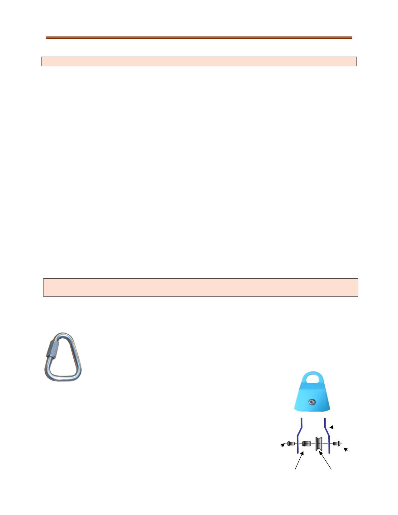
Using Carabiners Properly
A carabiner is strongest when loaded along its spine. Improper loading transfers the load to weaker
areas of the carabiner. This will dramatically reduce the strength of the attachment.
Tri-Links
Tri-links are designed to be loaded in three directions. They are very useful for anchoring
or rigging situations in which a carabiner would not be suitable due to undesirable side
loading.
Pulleys
Pulleys are used to change the direction of a pull on a rope. Some pulleys are
rated for single-person rescue only. The NFPA General Use minimum breaking
strength is 36 kN (8,093 lbf). For rope rescue, use the 4:1 pulley-to-rope ratio,
Side plates
meaning that the pulley size (also known as the “tread diameter”) is four
times the diameter of the rope.
Nut
Nut
Bearing
Sheave
11-9
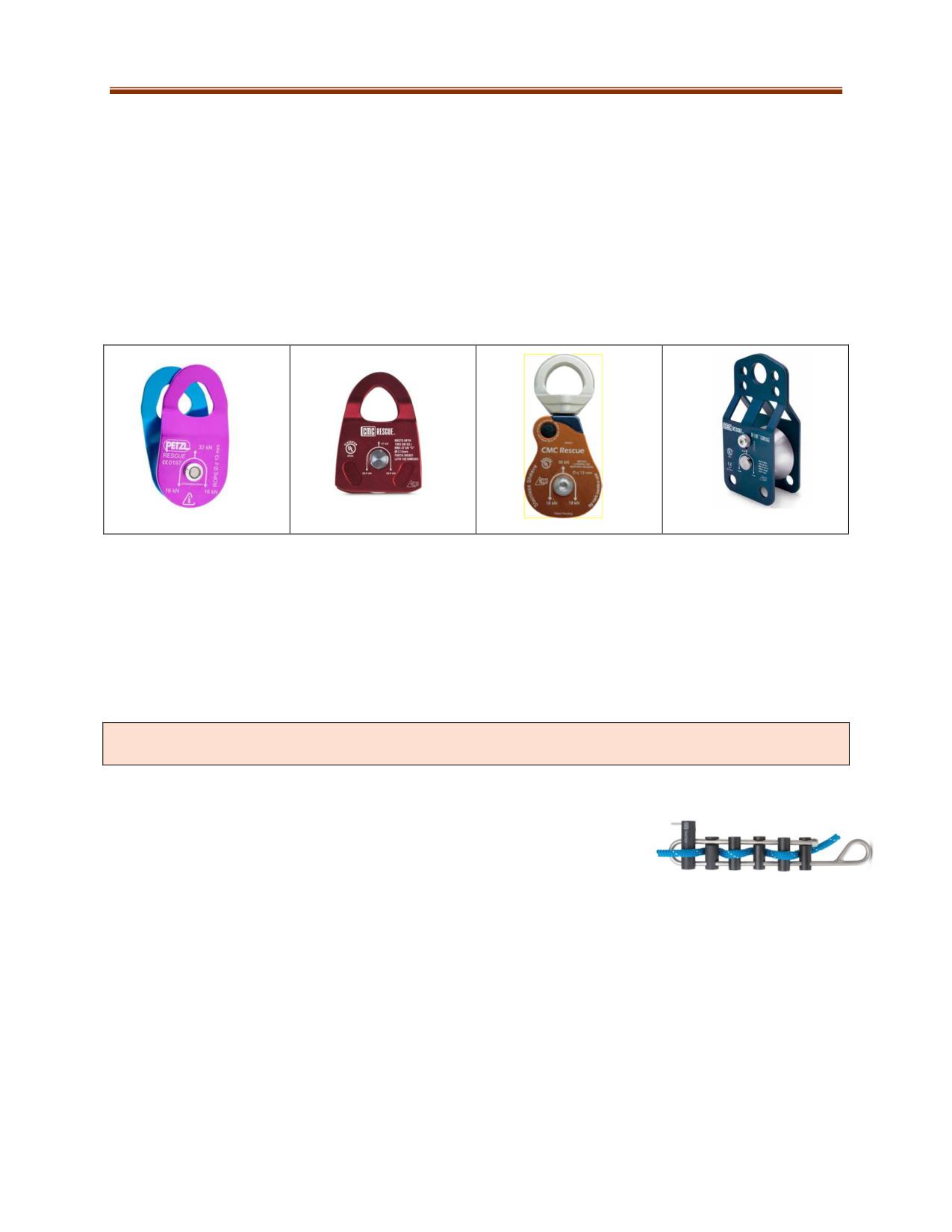
Types of Pulleys
Single and double sheave pulleys are used primarily for building mechanical advantage systems. Most
double sheave pulleys come with a becket. The becket is an anchor point for attaching a carabiner to
secure the end of the rope.
Prusik Minding Pulleys (PMPs) are designed to prevent the prusik from passing through the pulley.
Swivel pulleys with side plates have side plates that can be opened while under load, making them
more versatile than regular pulleys. They come in single and double sheave.
Knot Passing Pulleys have a large throat that enables knots or bends (that attach two ropes together) to
pass through the pulley. This pulley can also be used for directional changes or edge protection.
L-R: Single Pulley, Prusik Minding Pulley, Swivel Pulley, Knot-Passing Pulley
Descent Devices
If given a choice for rope rescue operations, lowering systems are preferred because:
They are simpler
They require less rigging
They use gravity as an advantage
They require fewer personnel to operate
Other commercially made devices are approved for rescue systems. Operating this equipment
requires specific training. If using these devices, follow all manufacturer’s instructions.
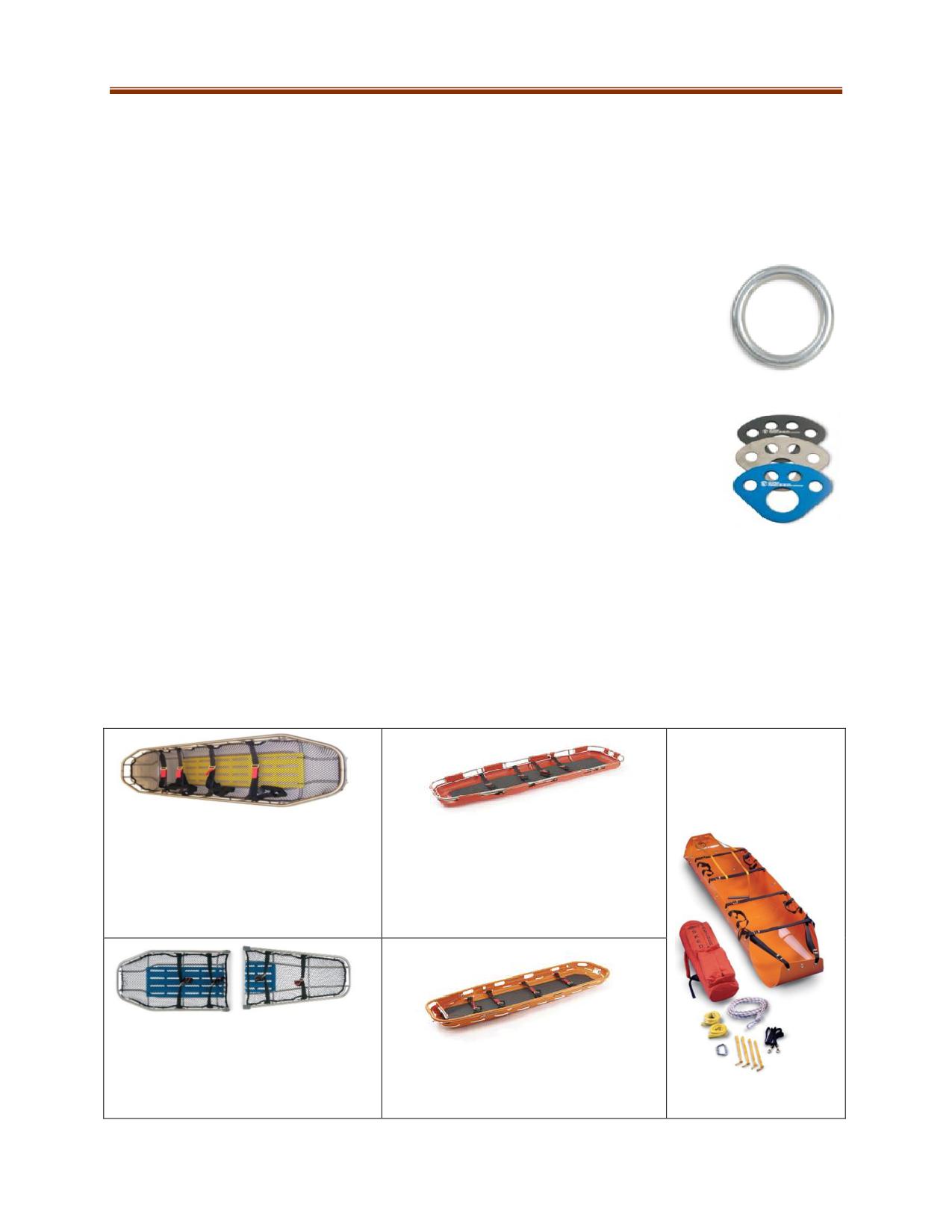
Brake bar racks consist of a number of brake bars attached to a rack
designed for the purpose of braking. The amount of friction applied to the
rope can be adjusted by adding or removing bars and increasing the space
between the bars. Brake bar racks:
Have a minimum breaking strength of 10,000 lbs (4,536 kg)
Threaded Brake Bar Rack
Should be tested annually
Are tied off with two wraps around the rack and two half hitches around the main load line
Are variable friction devices, some have a thicker second bar or hyper bar, which improve
control and help dissipate heat
Use in-line operation, can control two ropes simultaneously. Can have up to six bars and worn
out bars can be replaced.
Should be operated as per manufacturer’s recommendations. To avoid falling, make certain to
pre-tension the brake rack. Rescuers pre-tension brake racks every time the bar is used. To pre-
tension the brake rack:
1. Establish a plumb point. Hold the load-side knot tight about two inches past the access
11-10
edge and then around the first bar of the brake rack.
2. Tie off the rescuer holding the load side while making sure the load-side rescuer maintains
the plumb point.
3. The other rescuer then weaves the rope through the remaining bars and locks the brake
rack.
4. Attach the safety belay to the load, followed by the main line. Slowly work the belay system
until it is loaded.
Steel O-Rings are used for rigging anchor systems, and are also used as a Master
Point of Attachment.
They are very strong, with a strength margin of at least 20:1.
They can safely accommodate a main line, safety belay line, and rigging
harness.
Steel O-Ring
They have an inside diameter of three inches.
Anchor Plates for anchor systems make an excellent collection point and allow
rescuers to set up their systems quickly and cleanly.
Edge/anchor protection prevents damage to the rope and is commonly used when
attaching rigging to anchors. There are commercial products available or they can be
improvised on-site. Every effort should be made to prevent damage to the rope.
Anchor Plates
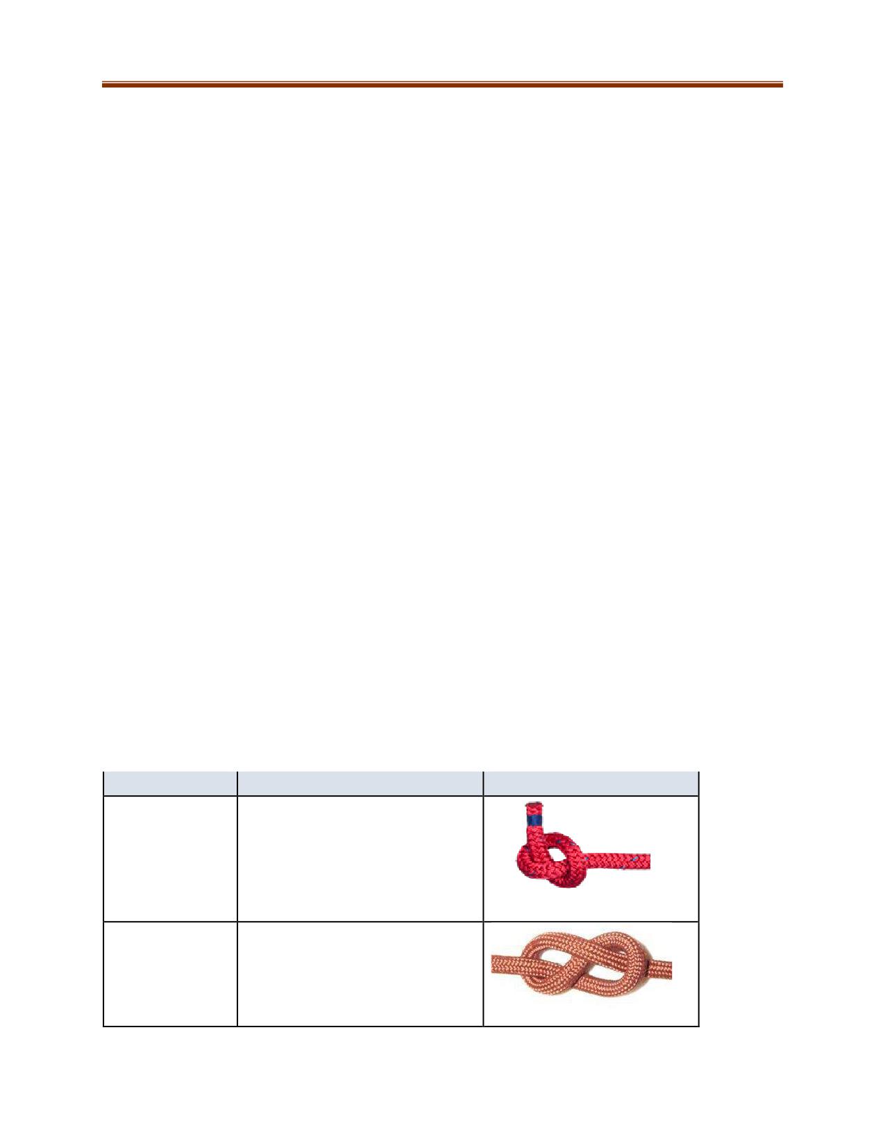
Rescue Stretchers
A variety of stretchers are available, but only ones designed for rope rescue should be used. Carry and
evacuation stretchers are not designed to handle the same stresses. Most stretchers are either plastic or
metal, and some come equipped with head protection and attachment points for carabiners. Read all
manufacturer's instructions and specifications when determining which stretchers to use. Stretchers
should be inspected before and after every use.
Flexible plastic:
Portable, light, fits
through small
Metal: has a metal tubing frame.
openings.
Some are lined with wire or plastic.
This type is very rugged.
Plastic: made of high-density
polyethylene shell with a metal frame.
Works well on dirt, grass and snow
surfaces.
Two piece: easier to carry to remote
locations.
Fiberglass/Composite: durable, light
weight, not affected by extreme cold.
11-11
KNOTS, BENDS, AND HITCHES
Knots are essential components of all rope rescue operations. The knot you use depends on the situation
and environment of the rescue. Rescuers must be able to tie the following knots, bends, and hitches in
all conditions. When deciding on a knot, consider the following factors:
The knot must have been proven to be safe for its intended use.
The knot must be strong enough for its role in the operation.
It must be easy to tie and untie.
All knots reduce the strength of the rope. The knot must not affect the strength of the system beyond
the acceptable safety factor.
For animations of the following knots, bends, and hitches, please visit http://www.animatedknots.com.
Terminology
Knot: A connection method used in rope or as in webbing to tie it to itself.
Bend: A tie that connects the ends of two ropes or webbing together.
Hitch: A tie that attaches a rope or webbing to another object such that if the object were removed the
tie would fall apart.
Bight: A bight is an open turn formed when a rope is doubled back upon itself making a turn but not
crossing over itself.
Standing Part: The inactive section of rope during the process of tying a knot.
Running End: The end of rope that threads through to complete the knot.
Loop: A turn of rope that crosses itself.
Tail: The free end of rope that extends from a knot.
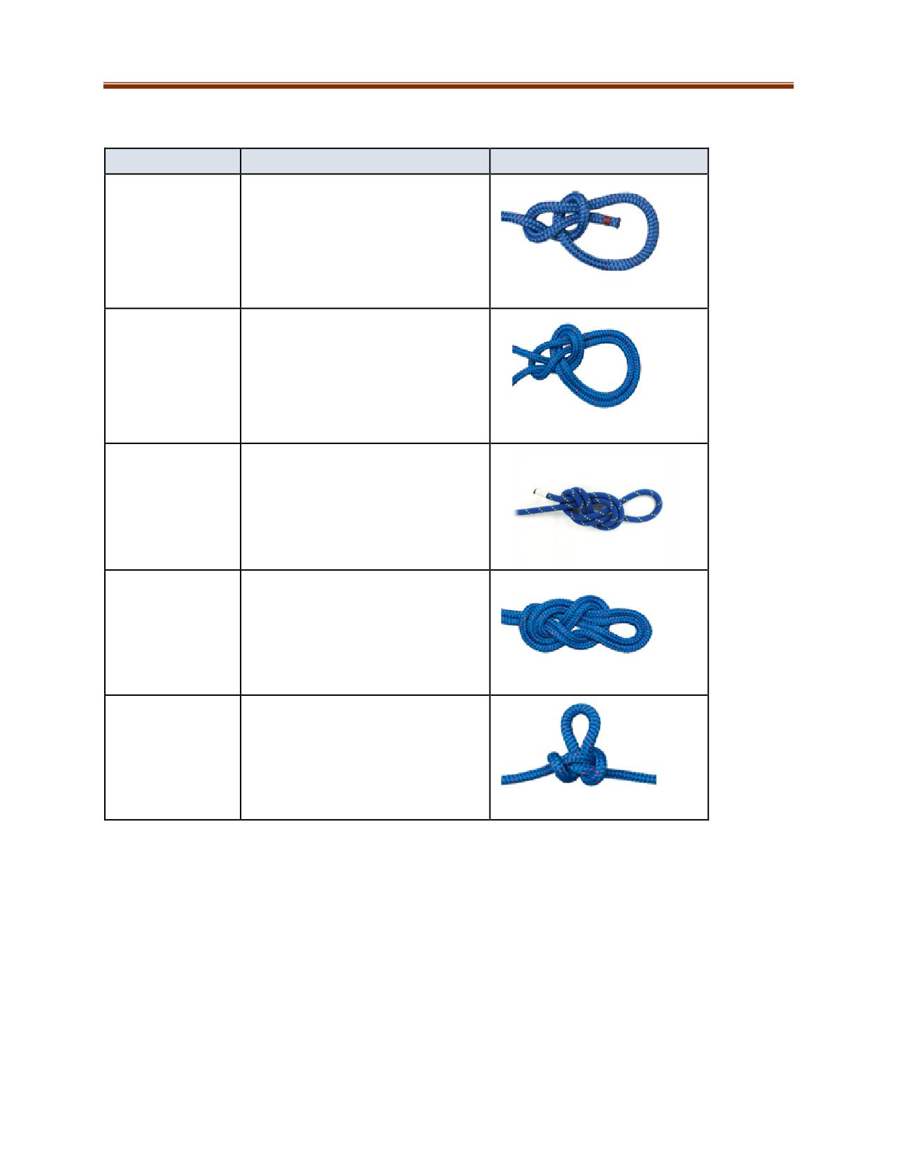
Safety Knots: Used to prevent fraying and to stop from sliding through a block, hole, or other knot.
Name
Notes
Diagram
Overhand Knot
Basic safety knot
Figure Eight
Basic safety knot
11-12
Knots
Name
Notes
Diagram
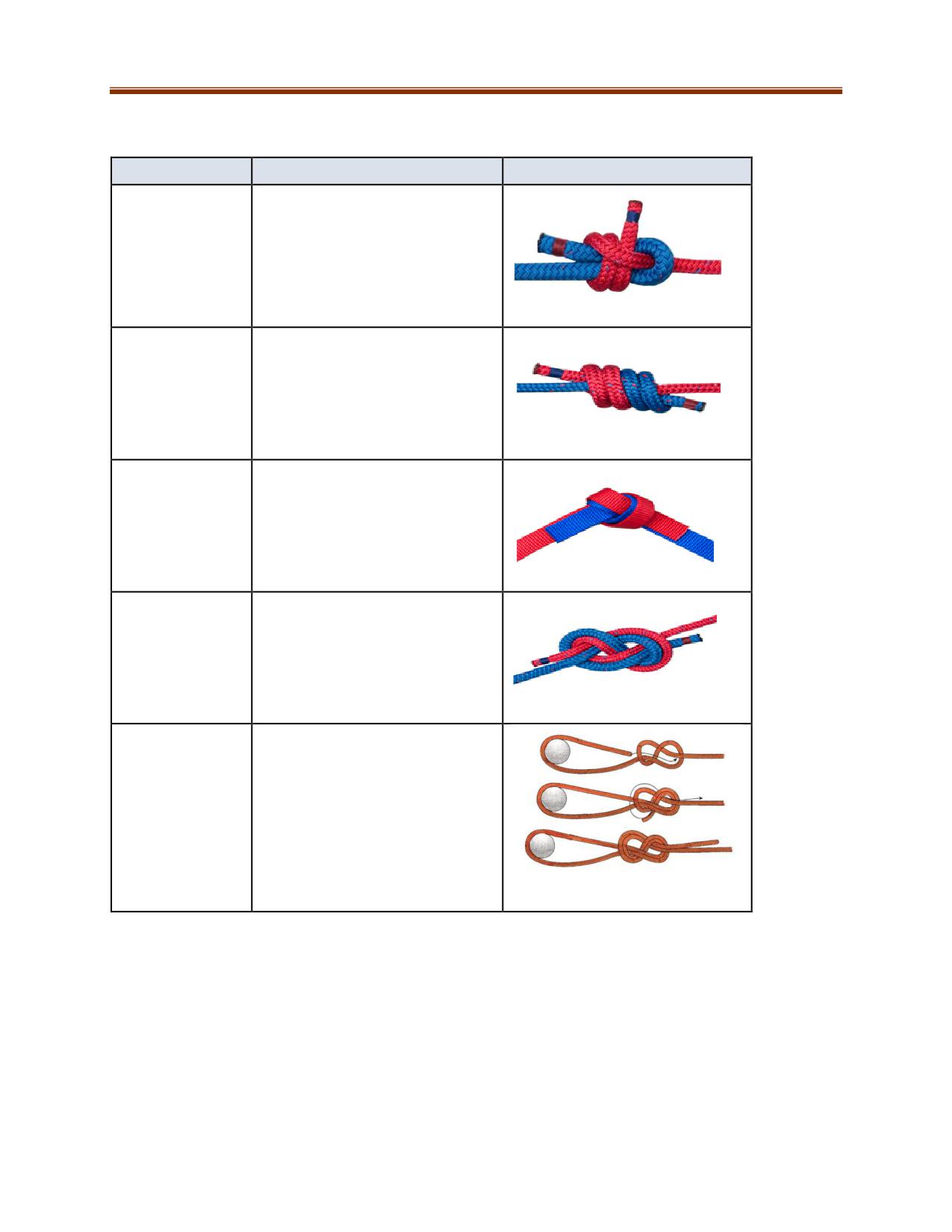
Bowline
A loop that will not jam, slip, or fail
Bowline on the
Creates a double loop
Bight
Figure of Eight on
Creates a loop that forms the main
a Bight
point of attachment
Double Figure of
Creates two loops that form the
Eight
main point of attachment
Butterfly Knot
Creates a loop in the standing part
of the rope that provides an
attachment point for multi-
directional use
11-13
Bends
Name
Notes
Diagram
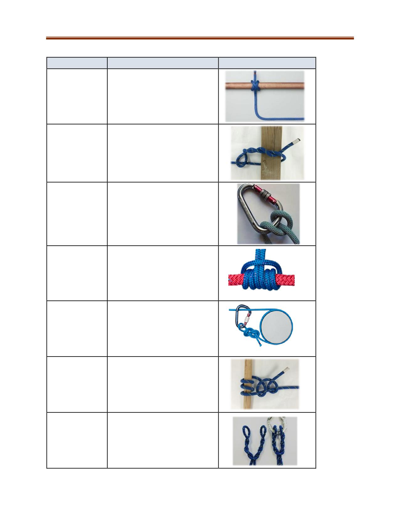
Double
Used for tying two ropes of
Sheetbend
unequal size together
Double
Used to join two ropes of equal
Fisherman's
diameter
Ring Bend
For connecting webbing to
webbing
Figure of Eight
Used to tie two rope ends
Bend
together end-to-end, in order to
extend them.
Figure of Eight
Used to anchor a rope around an
Follow-Through
object without the need of other
equipment.
11-14
Hitches
Name
Notes
Diagram
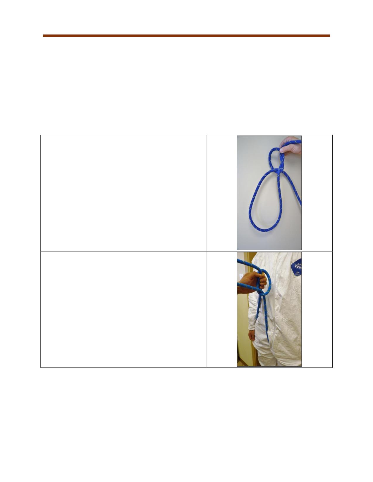
Clove Hitch
Used for securing a rope to a pole
or post. It is often used as a
starting point in lashing.
Timber Hitch
Used to hoist or drag timber or
pipes
Munter Hitch
Used for single-person belaying in
low-angle situations
Prusik
Friction hitch used to attach a
larger diameter rope without
knotting the rope. For hauling and
brakes, use a three-wrap prusik.
Tensionless Hitch
Used for anchoring a rope
Two Round Turns
Used to secure rope to a post or
with Two Half
pipe. Will take heavy strain without
Hitches
slipping or jamming.
Cat’s Paw
Used to secure rope to hooks and
rings
11-15
HARNESSES
Harnesses are designed to protect and hold the user's body. The type of harness used depends on the
task to be carried out. In rope rescue, they are most commonly used to raise or lower a casualty.
Butterfly Harness (Fig. 11-43)
The butterfly harness is used when only a rope is available to safely lower or raise a casualty from one
height to another. It is not to be used as a working or rescue harness. Any impairment to the circulation
to parts of the casualty’s body can have serious consequences. The rope diameter should be 11mm or
greater. Rescuers must also ensure that the duration of suspension is kept as brief as possible.
1. Measure four double arm lengths (approx. 20 feet, 6 m)
of rope across the body to provide enough working line
and tie an ordinary slip knot to form the first loop for one
of the casualty’s legs.
2. Place the loop around the casualty’s right thigh, well up
into the crotch. The rescuer’s left hand holds the eye of
the slip knot in the center of the casualty’s body just
below the chest.
11-16
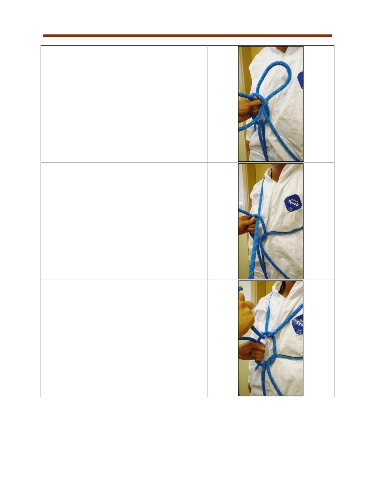
3. Wrap a second loop around the casualty’s left thigh,
well up into the crotch and form a third loop. Push the
third loop through the eye that is held secure by the
rescuer’s left hand.
4. Place the third loop under the casualty’s left arm and
over the right shoulder, then thread back through the
eye. Make sure the rope enters through the eye as
shown.
5. Continue the line and lay it across the left side of the
casualty’s neck. Continue along the casualty’s back and
under the right arm and bring it back through the eye on
the chest forming the fourth loop at the eye.
Note: There will now be an X pattern from the rope on
the casualty’s back.
11-17
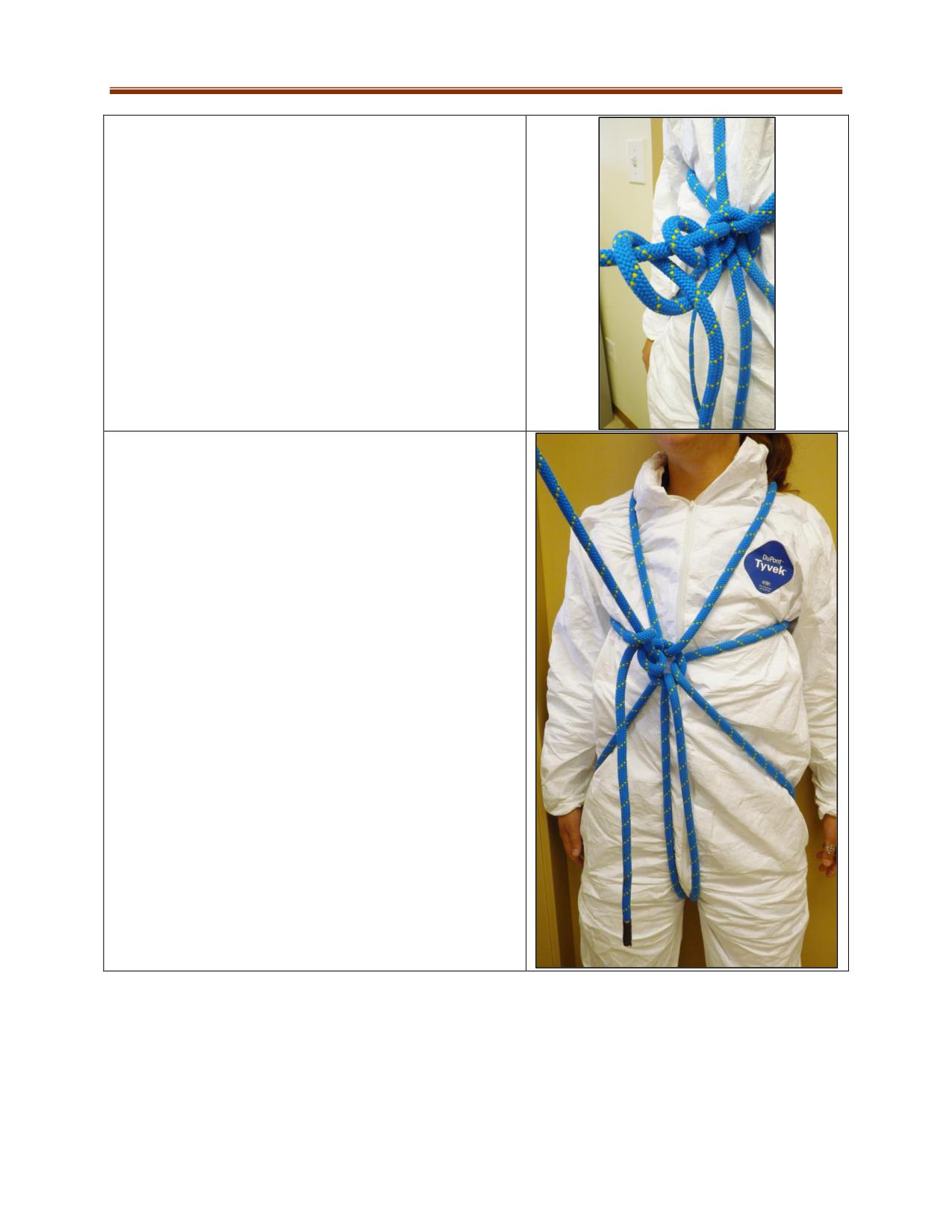
6. Tighten the eye snugly on all four loops by pulling on
the hauling line which closes the eye. Adjust the harness
for both tightness and comfort. Secure the eye to the
loops with two half hitches to prevent slipping and
tightening of the knot on the casualty’s body.
7. Tighten the half hitches to complete the harness. A
safety knot can be tied in the harness rope tail or the tail
can be connected to a separate rope line.
If possible, place padding between the rope and the
casualty’s body where there are points of pressure.
11-18
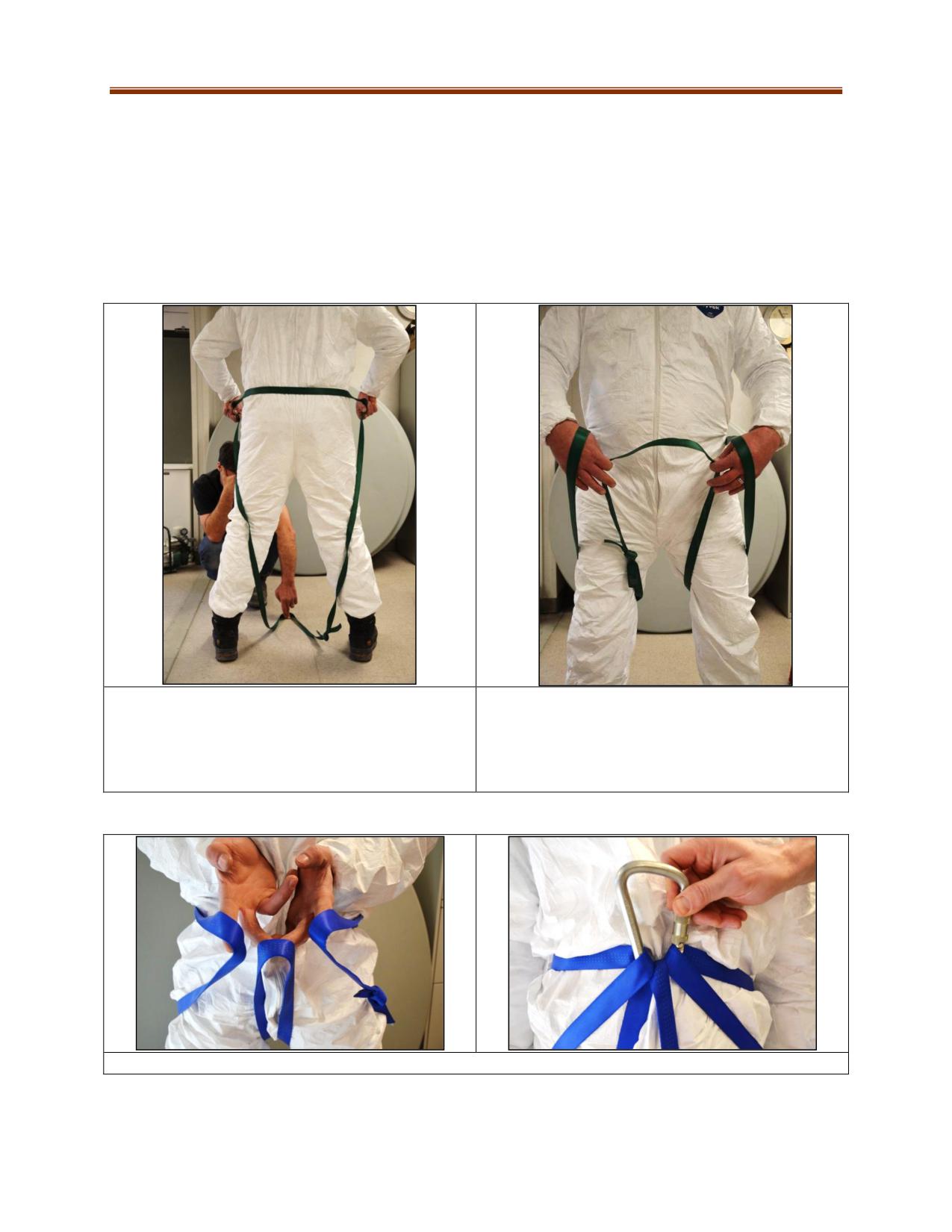
Webbing Harness (Upright)
Made from webbing, this harness is for an upright person who requires an easy, quickly made full-body
harness. It is to be used for short periods of time only, especially if suspended. There are many
variations of this method, including a commercially made ready-to-use type.
Start by building the seat portion, and then build the chest portion. Finish by connecting the two
together. Avoid placing the knot at locations that will cause pressure points on the wearer’s body.
Seat Harness
1. Use a 15 foot length of webbing tied together in
2. Hold the webbing at the waist line, hang a bend
a loop with a ring bend. If the fit of the harness is
behind and in between the legs of the wearer. Pull
too large, it can be adjusted at the ring bend by
the hanging bend through the legs to the front to
lengthening the tails.
meet the two made at waist level.
VERSION A: 3. Connect all the bends together with a carabiner.
11-19
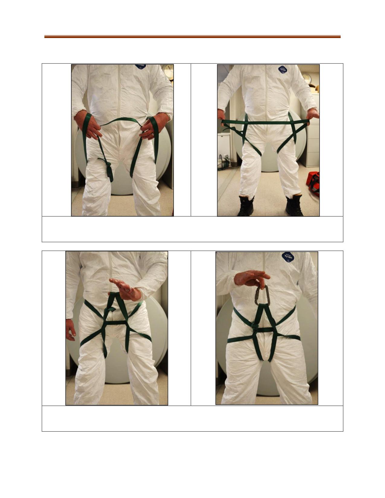
VERSION B (Fits smaller people better): 3. Grab the hanging bend that came from beneath the legs,
separate, and pass it under each bend created at the waist. Pull these outwards to adjust fit, bring them
together in front of the casualty, and attach them with a carabiner.
4. Have the wearer hold the carabiner while checking the fit and then begin building the chest portion.
In some cases it is easier to build the chest portion first and let the carabiner hang. When the web seat is
ready attach the two portions together to form the full body harness.
11-20
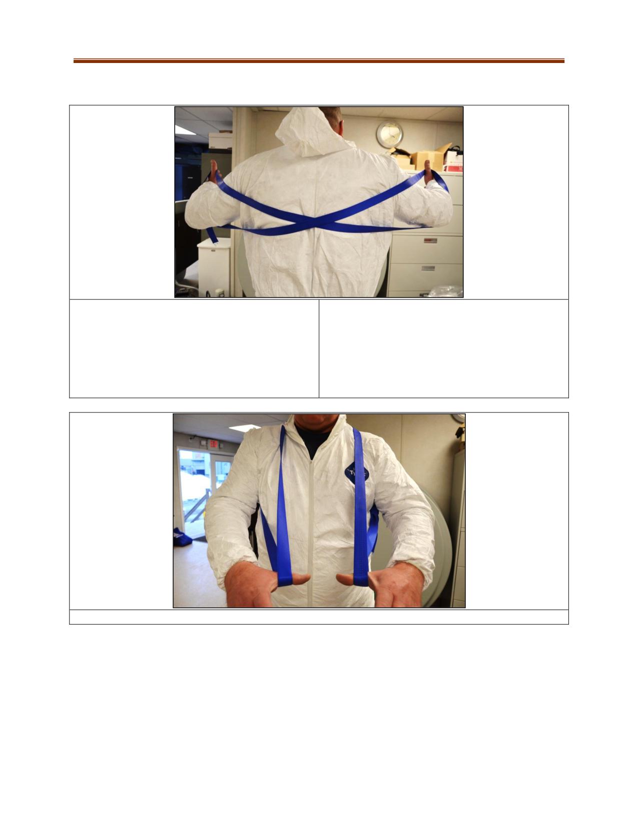
Chest Harness
1. Use a 12-foot length of webbing connected in a
2. Twist and hold the webbing so that there is a
loop with a ring bend. If the harness is too large for
loop for each arm. Check that there is a crossover
the wearer, it can be adjusted at the ring bend by
of the web on the person’s back. Modifications
lengthening the tails. Avoid placing the knot in
may be required if physical injuries are aggravated
such a way that it creates pressure points on the
by the webbing.
wearer’s body.
3. Pull the two arm loops to the front of wearer to snug and adjust the length if required.
11-21
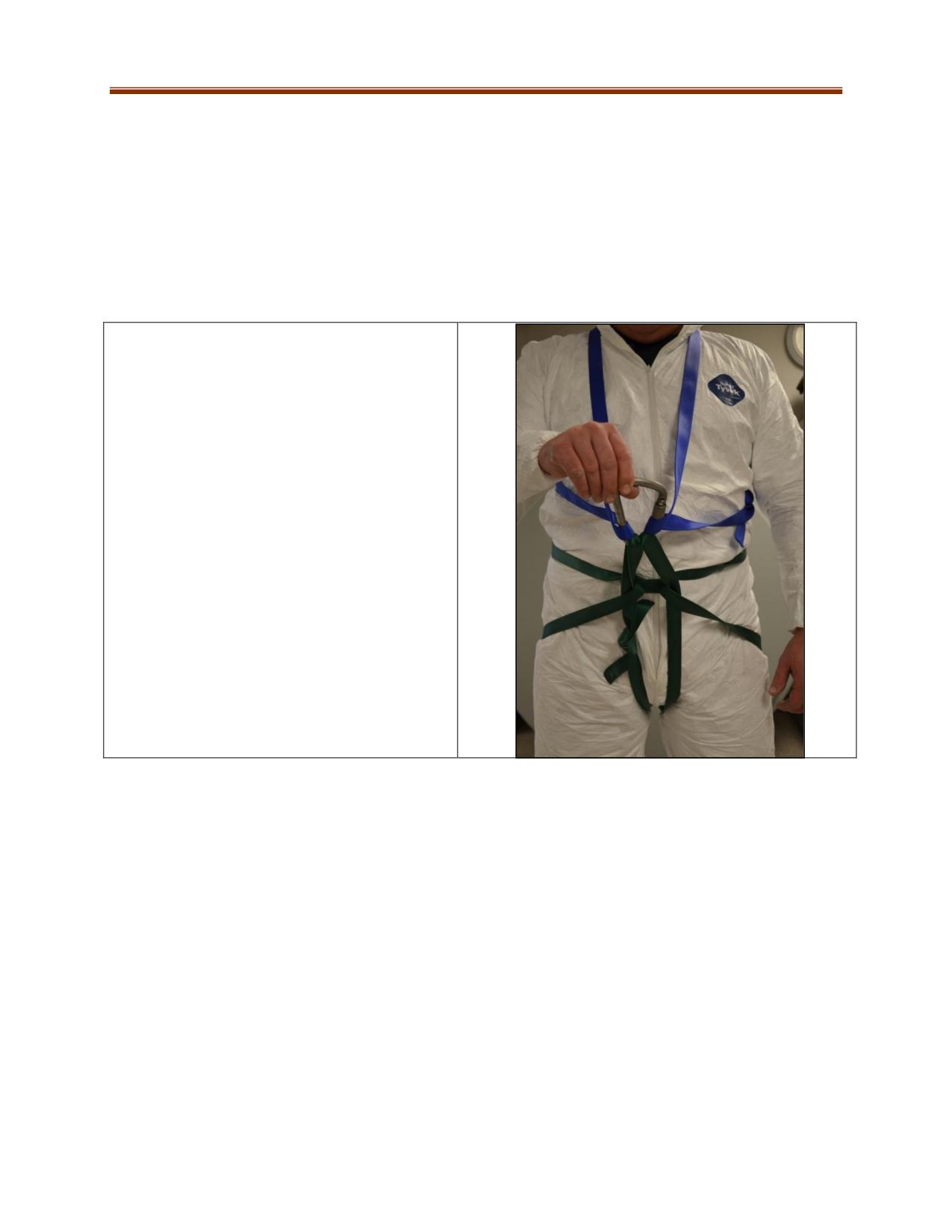
Connect the seat and chest harness together with the carabiner to form the full body harness. Complete
the following checks:
Have the wearer lean back slightly while holding the carabiner. The weight should be on the seat
portion and it should be comfortable.
The harness should be snug so that it will not slip off during movement.
Tie safety knots on any hanging ring bend tails that could interfere with rigging.
The carabiner must not be side loaded and gate lock must be checked before and after attaching
rope rigging systems.
4. If there is a long distance between the seat
and chest connection points that prevents the
use of a single carabiner to attach together, the
following methods can be used as long as both
harnesses are securely attached to each other:
Add another carabiner and connect one
to the seat and other to the chest
harness. To complete connect the
carabiners directly to each other.
Add another carabiner. Use a short
webbing or prusik cord to connect
between chest and seat harness
carabiners.
11-22
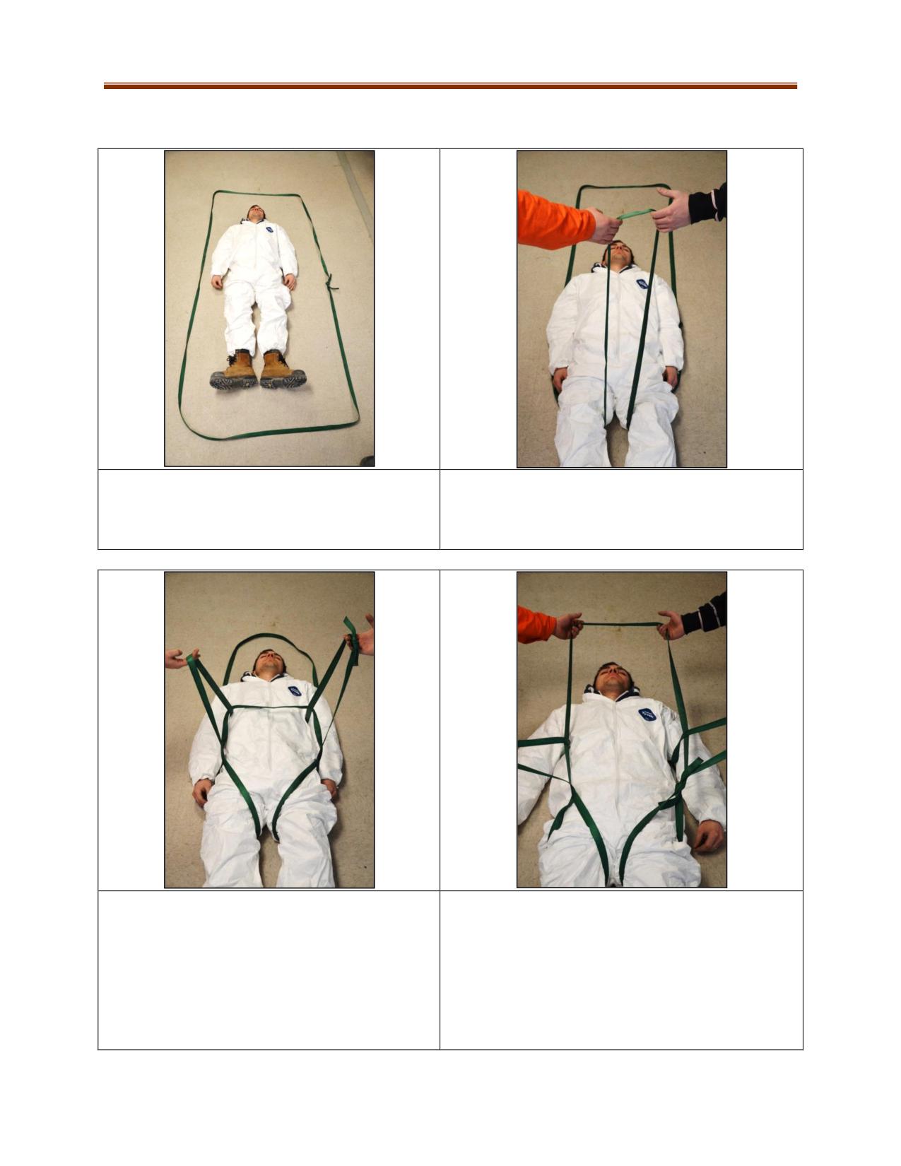
Webbing Harness
This harness is used for casualties who are either unconscious or supine and require a rapid rescue.
1. Use a 24-foot (7.3 m) webbing tied together
2. Lift legs and pull the webbing up through the
with a ring bend to form a large loop. Encircle the
thighs.
casualty that requires rescue.
3. Grab a portion of web lying on the floor by
4. Take the web portion that lays across the chest
casualty through the loop end from the legs.
area. Pull and place it behind the casualty’s neck.
Option:
Pull the two new bends to snug the webbing
around the wearer or connect them together
with a carabiner. Rescuers can now drag or pull
the casualty to be rescued like a sled.
11-23
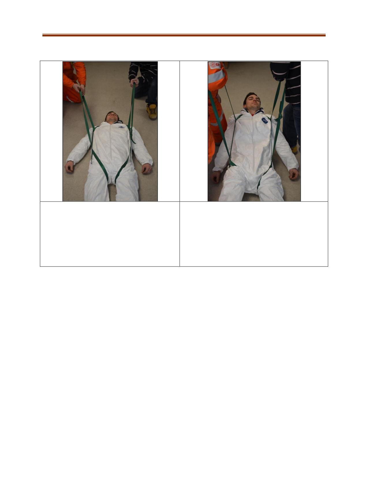
5. Pull on the webbing to snug the harness to the
6. If the web was placed behind the neck, the
wearer. The casualty can now be dragged or
rescuers can also lift the casualty off the floor or
pulled from a hazardous location to a safer area
obstacles by putting webbing straps over their own
by the rescuers.
shoulders. The rescuers can now move together to a
safe area in an almost full standing position.
For a rapidly applied harness, the webbing and the
part behind the head causes minimal discomfort.
11-24
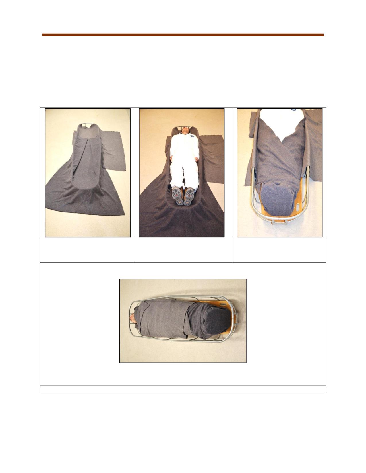
Blanketing a Stretcher
There are various methods to blanketing a stretcher but the objectives are the same:
Provide the casualty with warmth for shock or environmental conditions.
Comfort the casualty by ensuring there is nothing that can cause pressure points on the
casualty’s body.
Allow a rescuer to quickly access the vital signs and injuries of the casualty.
Keep the blankets from being loose and potentially getting into rigging systems.
1. Lay blankets as shown. Avoid
2. Load casualty in, leave a space
3. Wrap around legs.
any bumps that could cause a
at least 4” from head to the rail if
Keep loose at feet if a rope tie-
pressure point
possible
in is to be used.
4. Finish by pulling the upper body blanket over and tucking it in.
11-25
Basket Stretcher Tie-In
Basket stretcher tie-in procedures are used to ensure the casualty:
is secured sufficiently to reduce aggravation of injuries for during transport
does not slide around or slip out of basket when transporting over uneven ground
well secured while moving from one height to another
does not move within the basket when it needs to be moved from partial tipping to a full
vertical position
is fully secured in the basket when the rescuer cannot accompany them for the duration of a
rescue
There are many tie-in methods due to the variation of styles and design of rescue basket stretchers. One
method may work perfectly on one basket and not well on another. Tie-in procedure may need to be
modified due to factors such as:
basket width and length
location and number of support rails and cross members
plastic versions that require a method that does not put pressure directly on the plastic portion
which can cause ripping
size and shape of the casualty
orientation of casualty in the basket such as on their side (lateral)
type and location of the injury and access to casualty’s body parts
the speed at which the casualty requires to be moved for safety reasons (danger)
webbing/rope for tie in is too short or too long
Commercial tie-in kits are available, ranging from seat belt style to webbing kits designed specifically for
certain baskets.
Blanketing is required to protect for the casualty from tie in contact points to the body. Padding
underneath the casualty is required when long travel times are encountered. Rolled blankets can be
used to make up spaces to reduce movement between the feet and the stretcher, casualty’s head and
stretcher, or at their sides. Using padding reduces sliding, provides comfort and can protect injuries. The
casualty’s arms should be placed under the blanket and at their sides whenever possible to make the
tie-in process easier.
Items such as oxygen therapy units must be secured in the basket if there is a possibility of them falling
out.
Care must be taken to protect the casualty’s face from being whipped by the tie-in material.
The tie-in must be tight enough to provide the tension needed but not so much that it will cause patient
discomfort. If conscious, ask casualty as the tie progresses for any concerns.
11-26
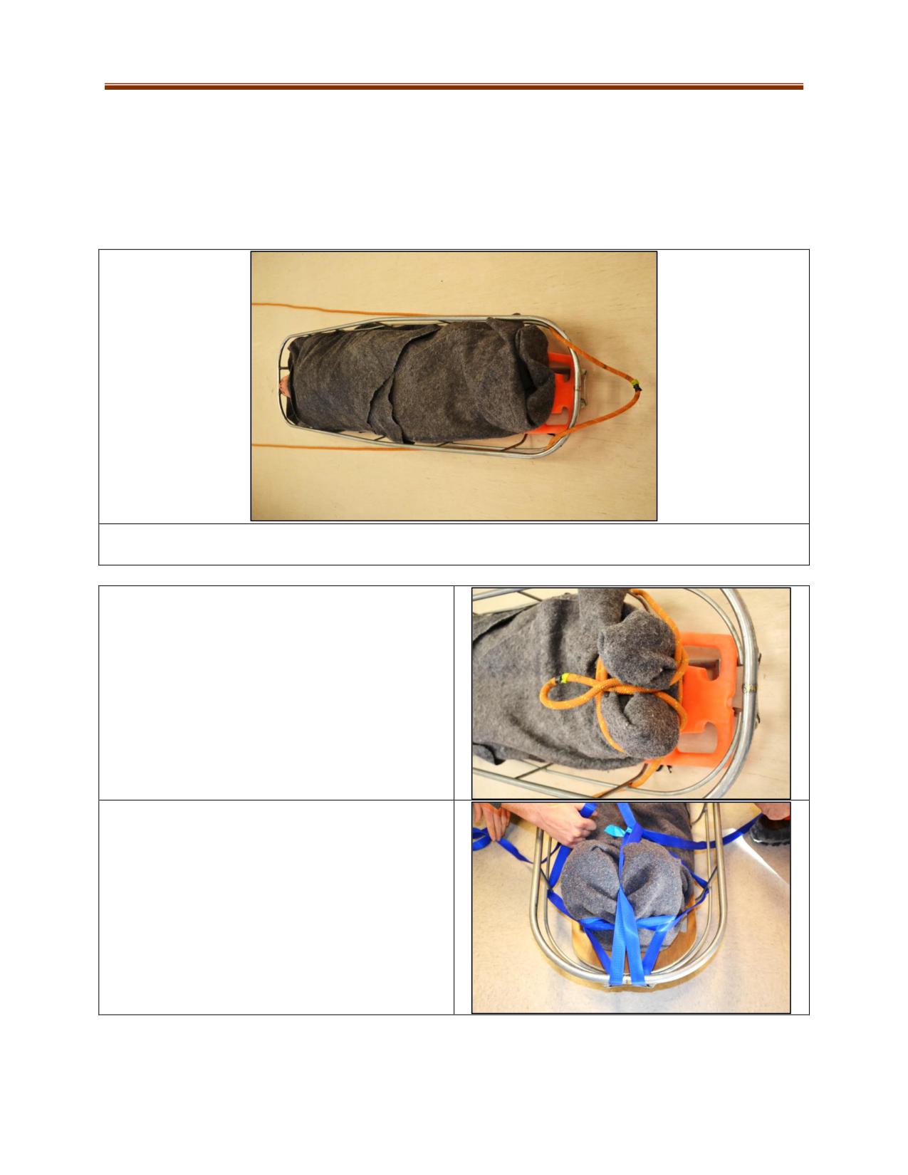
Herringbone Tie-In
The herringbone tie-in can be accomplished with either webbing or a rope (use a large diameter such as
11mm to avoid discomfort to the casualty). The common length of a dedicated tie-in web or rope is at
least 60 feet (18 meters). If done correctly the herringbone can be easily “unzipped” after undoing the
last securing knots, which can be useful if a casualty needs to be removed from basket quickly and
transferred to an ambulance cot.
1. Using a dedicated tie in length, thread half of it through the bottom section of the stretcher, below
the lowest cross member. Half the tie will be each side of the stretcher.
2. If using a rope, lay the center of the tie in on top
of the stretcher rail (1st loop), wrap around the
feet with a clove hitch, pull the loop between the
feet over the clove hitch. This can also be
accomplished by wrapping the casualty’s feet,
making a clove hitch then pulling some slack to
make the first loop that is then placed from the
feet bottom over and between the feet. Twist the
loop if it is too long.
3. If using webbing, form bights on each side of
stretcher. Pull one through the stretcher and push
through the 1st loop at the feet. Repeat with the
other side to make a third. Keep tension as the tie
in progresses. If there are double rails on the
stretcher, it is preferred to thread under the
bottom one as this pulls downward for a tighter fit.
11-27
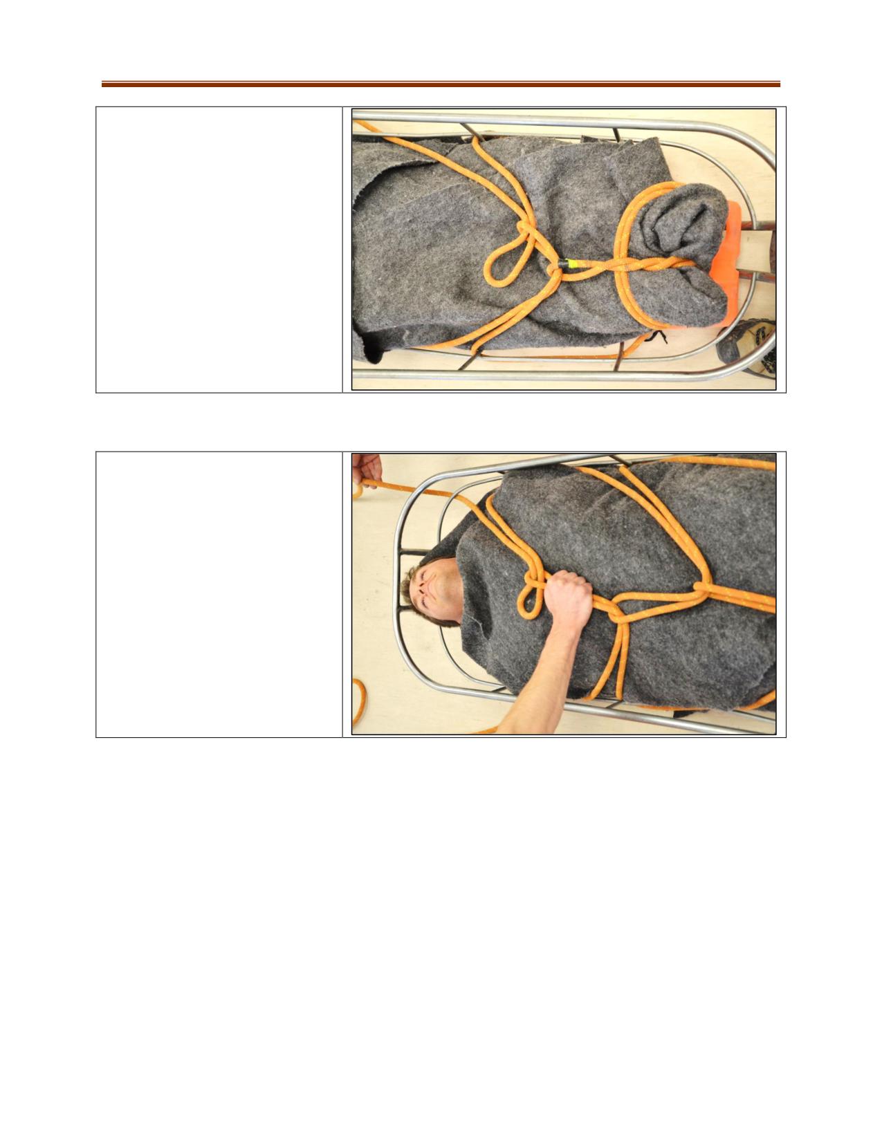
4. Work up the stretcher repeating
Step 3 using each cross member in
turn. Maintain tightness as it
progresses. Avoid placing bight
ends over knees, groin, diaphragm
(just under rib line) and any
injuries. The last bight loop must be
well away from throat.
5. When you reach the top cross
member, tighten each running end
over the casualty’s shoulders
making sure they are well padded.
Tie off on the stretcher frame with
clove hitches.
11-28
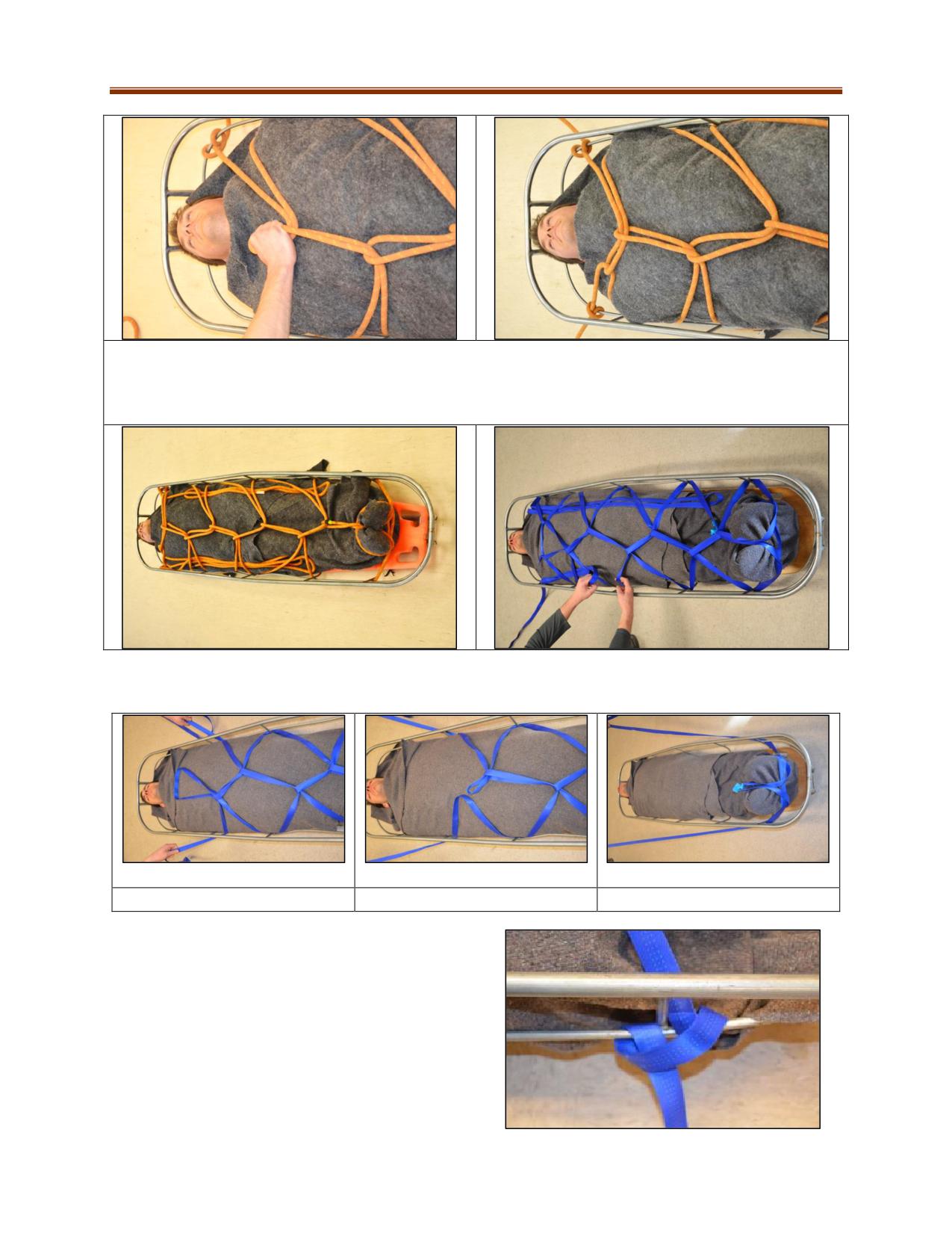
6. Check tightness of the whole tie-in starting at feet. Move final clove hitch towards stretcher cross
member near casualty’s shoulder or fully trap the knot by tying around both sides of it. Place left over
rope or webbing under all to keep from falling out or interfering with rigging systems. Bottom Right: Tie-
in using webbing.
Releasing the herringbone basket stretcher tie-in to let patient out of stretcher:
1. Undo last part of tie-in
2. Pull bends out each side
3. Unwrap feet
Example of trapping cross member with a clove hitch:
11-29
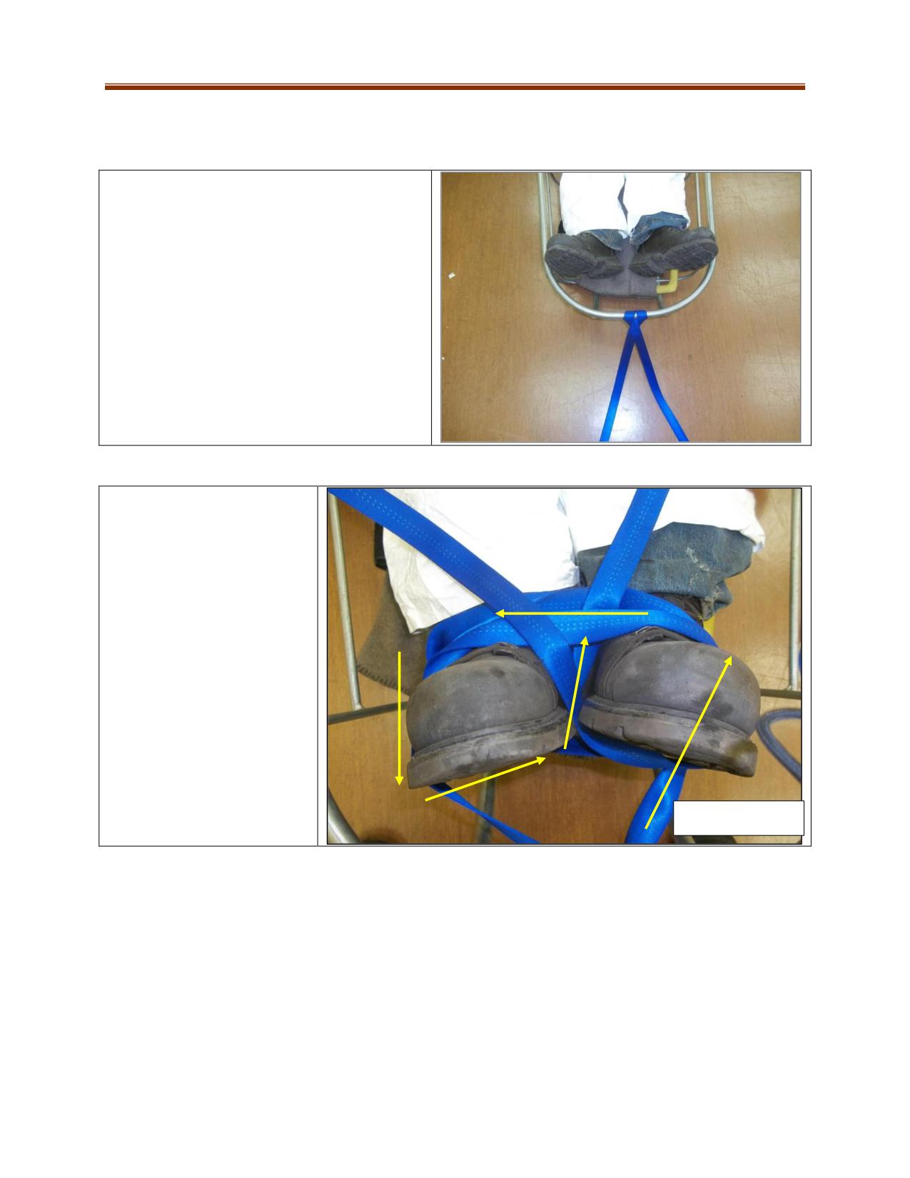
Diamond Lashing
This method is uses webbing to secure a casualty in a stretcher. It takes longer to remove from a
stretcher than the herringbone method.
1. Start with an 18 m (60 ft) length of webbing
(minimum diameter 25 mm). Fold in half and
wrap around the centre of the top rung on the
foot end of the stretcher.
2. Looking from the bottom of
the stretcher, with the right
tail go around the outside of
the left foot and continue
along the top of both feet to
the opposite (right) foot, then
go around and up through the
middle. This tail will continue
through to the left side when
looking from the foot end of
the stretcher.
START HERE
11-30
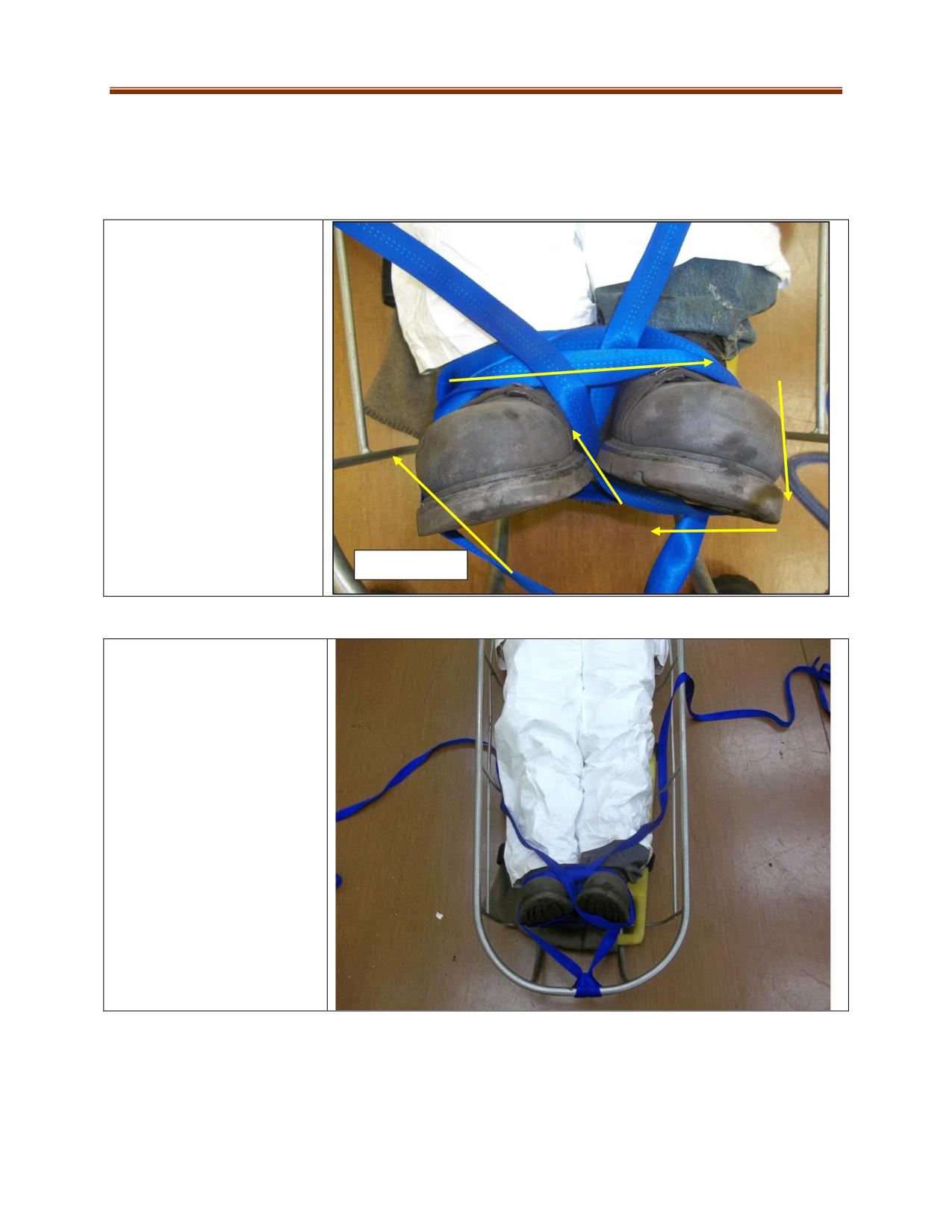
3. Looking from the bottom
of the stretcher, go around
the outside of the right
foot with the other web tail
and continue along the top
of both feet to the opposite
(left) foot. Go around and
up through the middle. This
tail will continue through to
the left side when looking
from the foot end of the
stretcher.
Start Here
4. Both web tails will
continue up to the opposite
sides to the first rung on the
stretcher incorporating the
first post.
11-31
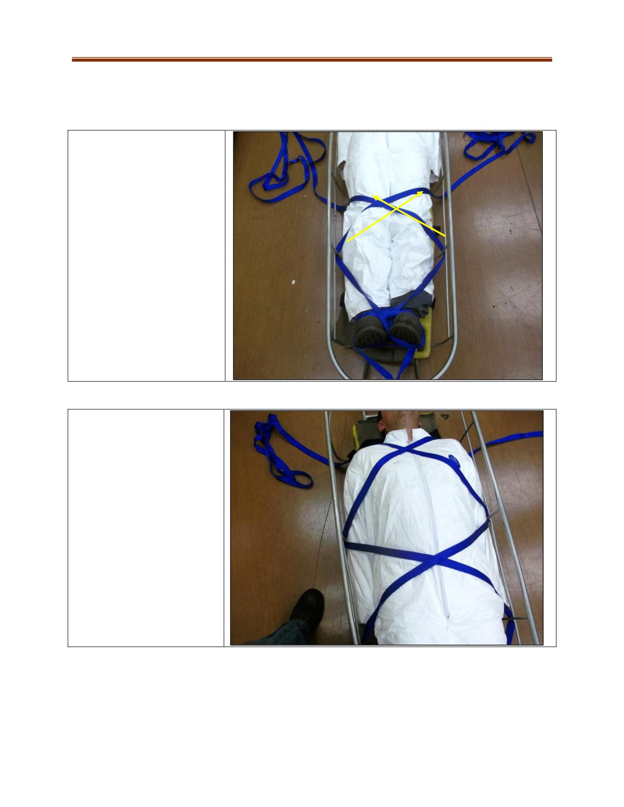
5. Continue to crisscross up
the patient to the opposite
sides of the stretcher creating
diamonds across the body
incorporating
the
posts.
Always use the bottom rung.
6. The last cross should be
across the chest area and over
the shoulders to hold them
down.
11-32
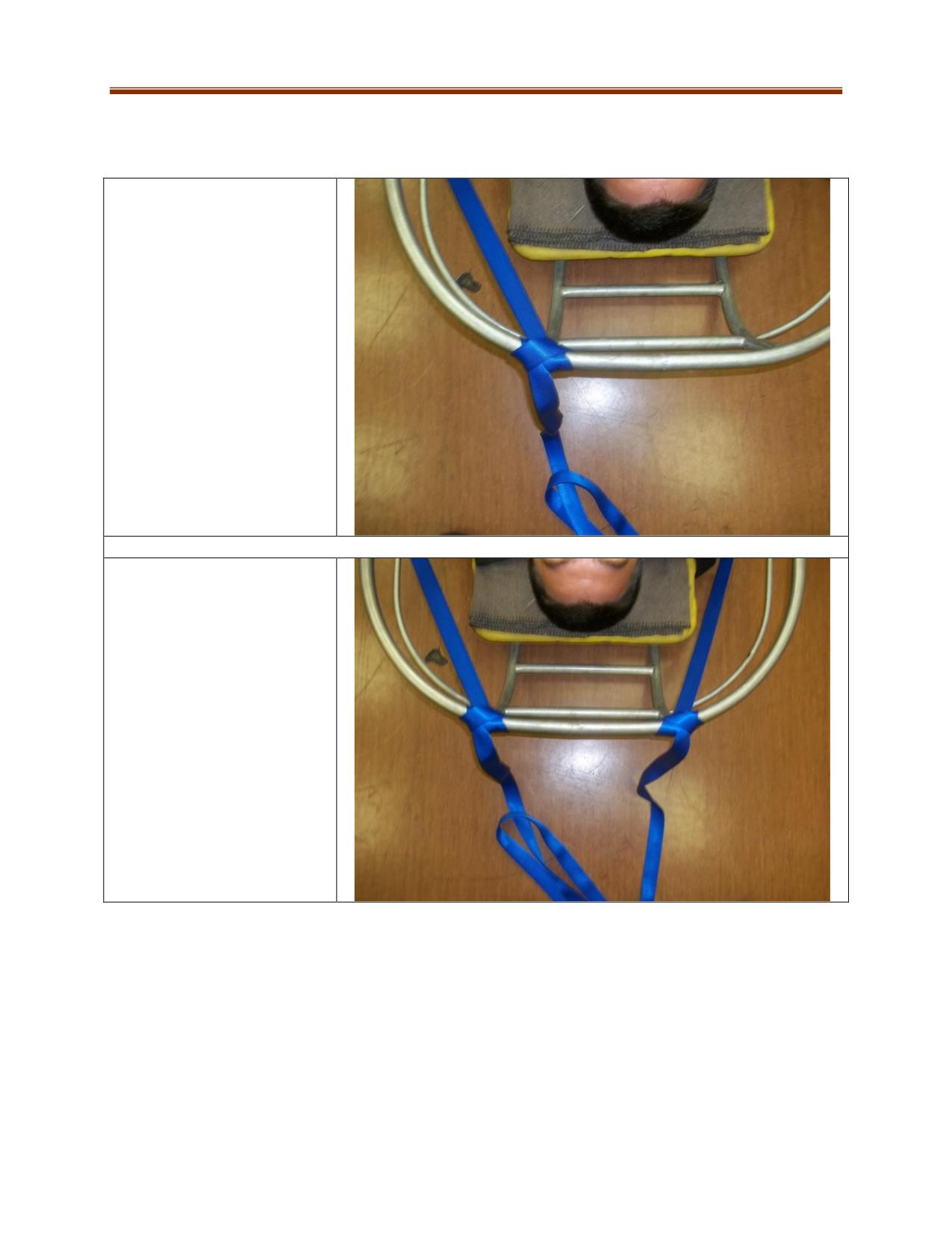
7. Continue to the head of the
stretcher tying a clove hitch on
the top rung, making sure to
incorporate the post.
8. Repeat the same with the
opposite side.
11-33
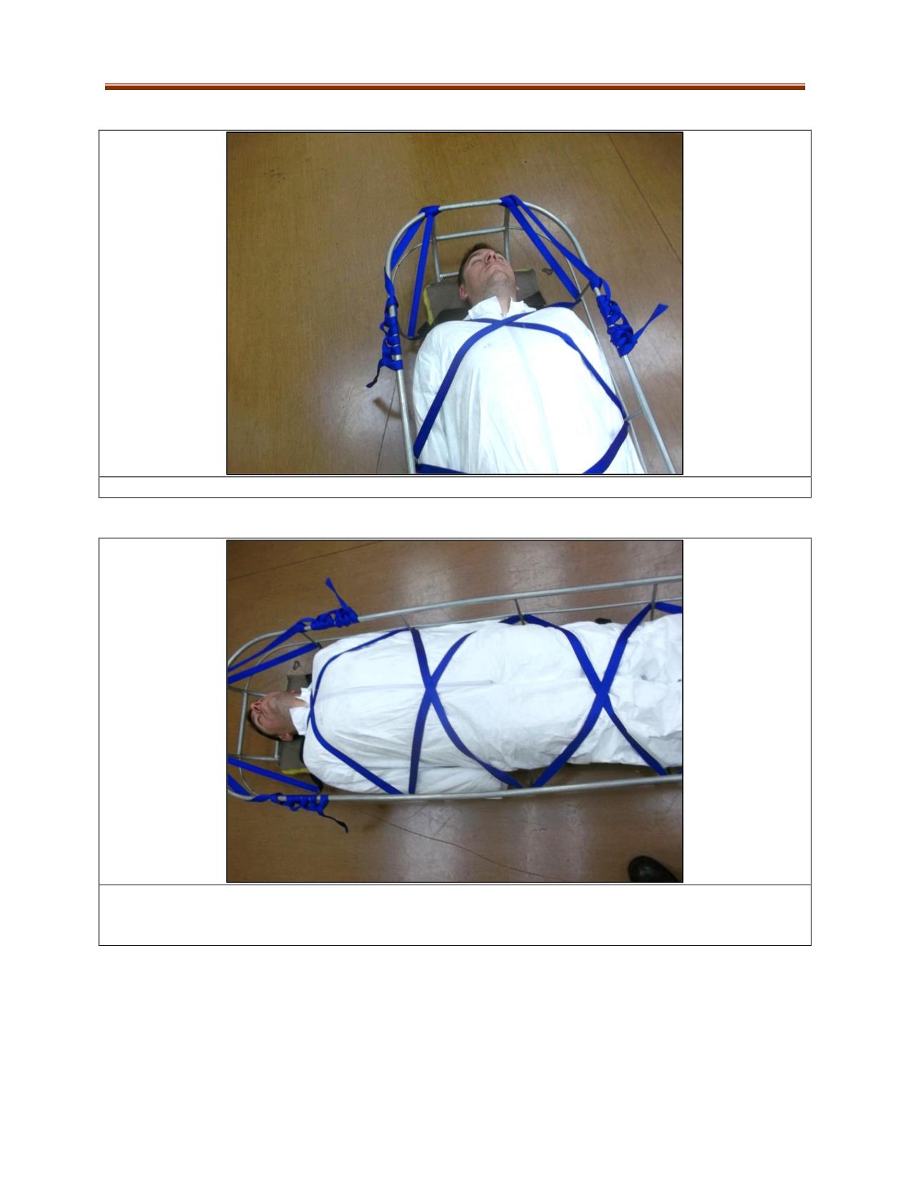
9. Secure the loose ends OPTION: Follow down the two sides tying half hitches.
10. When done the patient should be secured to the stretcher with no excessive slack in the webbing
and patient should not be choked with the last cross on the chest. To test the system, lift the head end
of the stretcher up to vertical, the patient should not drop within the lashing.
11-34
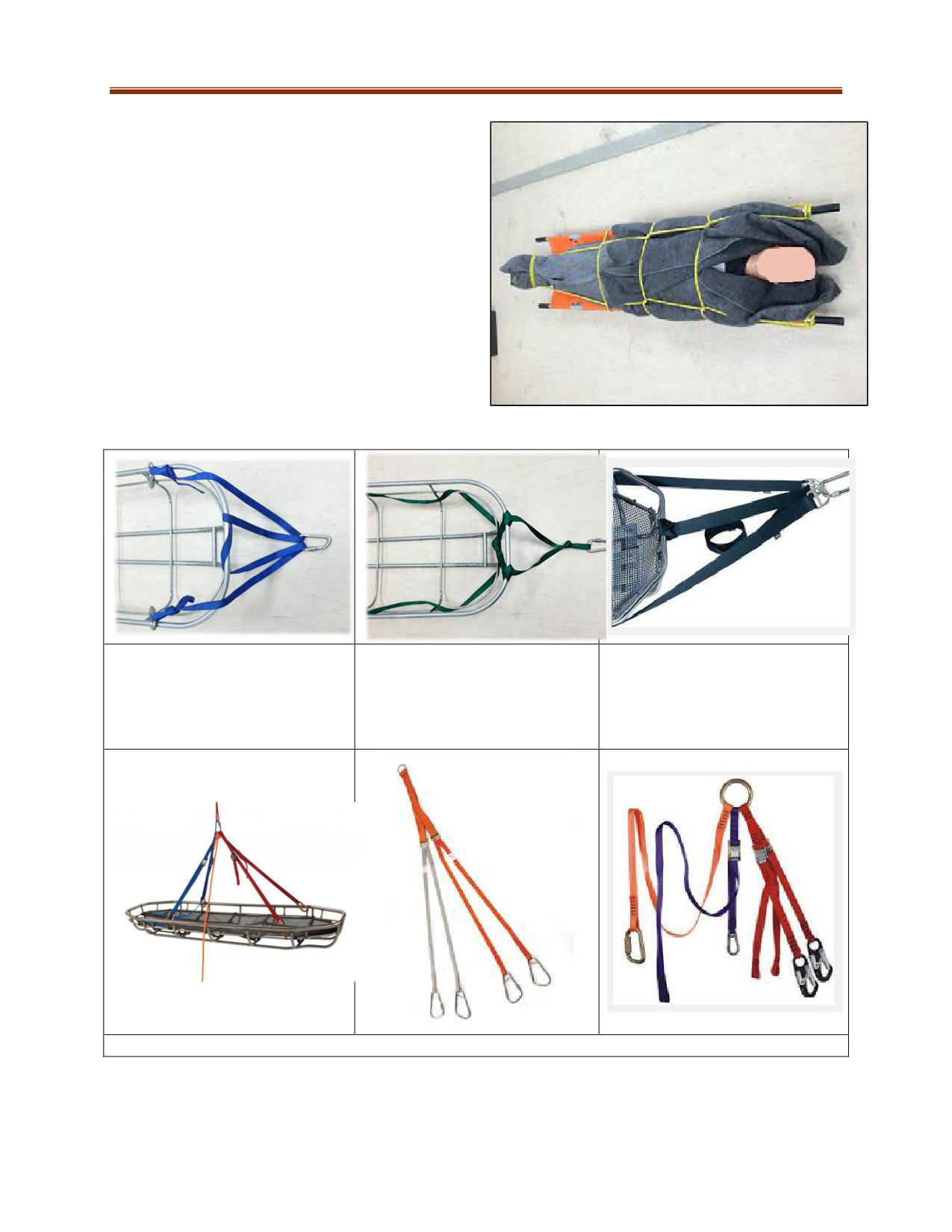
Furley Stretcher Tie-In
This tie-in securely lashes a casualty to a furley
stretcher.
Stretcher Bridle Examples
Typical stretcher attachment tied
Attachment that works well for
Example of a commercially
with webbing
plastic baskets. The web tails
manufactured bridle
can be used to secure an inner
support piece such as a spine
board.
Commercially available stretcher attachments
11-35
ANCHORS
High forces are often encountered during rope rescue operations. Anchors that are solid and
unmovable relative to the load being applied (“bombproof”) are needed to connect the systems.
Because it is often difficult to assess the strength of an anchor, rescuers should be incorporating two or
more anchors into the system whenever possible.
Anchor Leverage: To reduce leverage on a vertical anchor, secure the anchor attachment close to the
ground. Minimizing the effects of leverage will maximize the strength of the anchor.
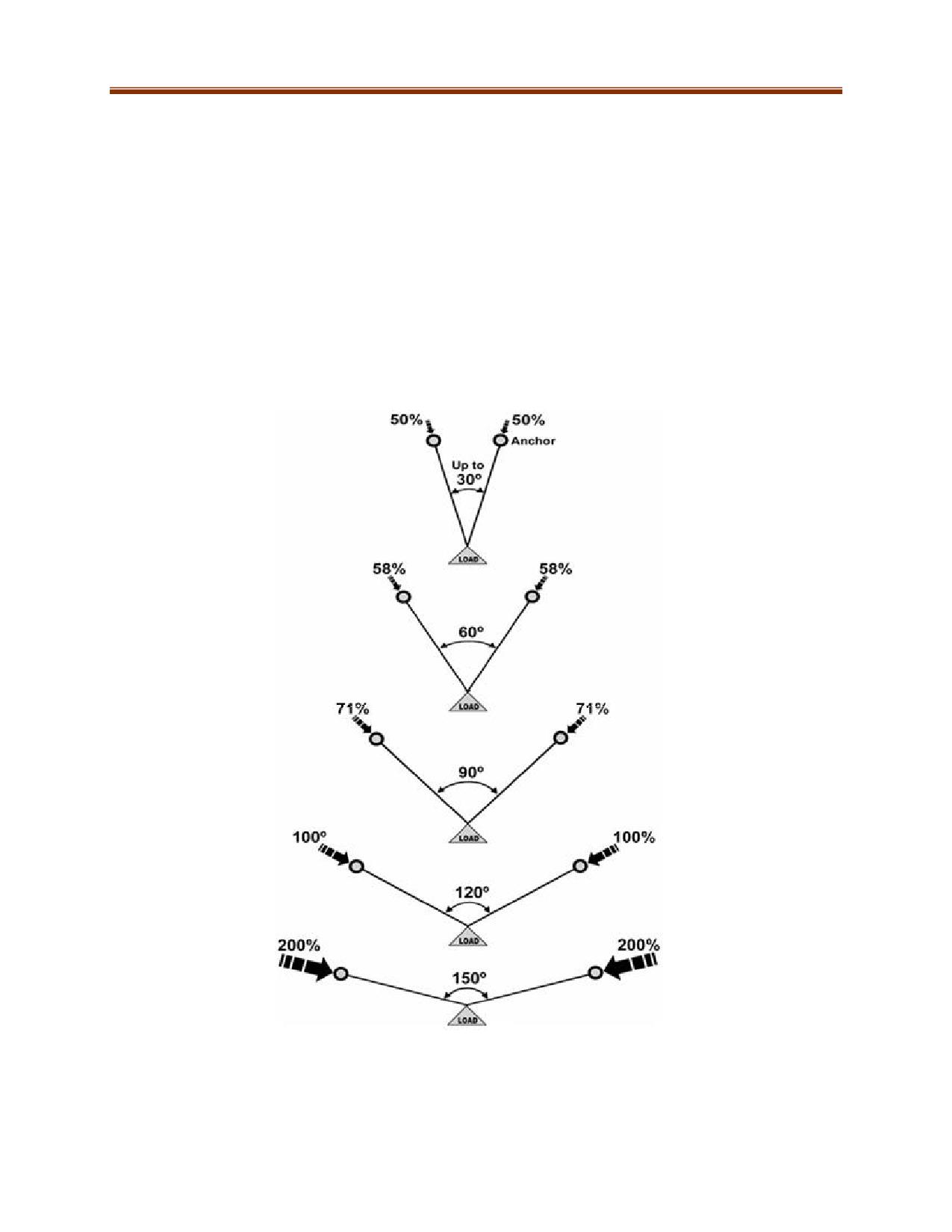
Critical Angle: Sometimes, anchors will not be in line with the rescue. In these instances it might be
necessary to build a bridle anchor from two anchor points. These angles will create vector forces on the
chosen anchors. It is imperative mine rescuers understand these forces.
Fig. 11-1: Different angles and their respective vector forces
11-36
Anchors need to be examined by the team prior to attaching webbing or rope for:
Location
Strength
Direction the load will be travelling
Stability
Sharp edges
Abrasive surfaces
Contaminants
Hot surfaces
Whether to use high or low anchor points
Whether there is enough space to operate safely
Natural Anchors
Trees are the most common anchors used by rescuers, but even large trees might not be suitable.
When selecting a tree to use as an anchor:
Use large, healthy, and living trees.
Make sure the tree is well rooted and doesn’t rock.
Use a tree with a diameter of more than 25 cm (10 in) if possible.
Check the bottom of the tree where webbing or rope will be attached for things that might
damage the anchoring material.
Make sure the roots are not damaged and soil is undisturbed.
Rocky outcrops and boulders can provide a very strong anchor. When selecting rocky outcrops and
boulders:
Make sure they are large and stable enough for the load weight of the rope system.
Make sure they are not fractured and shaped so that the web or rope won't slip up and off.
Avoid sharp edges if possible. If that is not possible, add padding to the edges to protect the
anchor system.
Find level, stable ground not that does not slope downwards toward an edge.
Avoid boulders sitting on a bed of smaller rocks as they can be moved with little force.
Structural Anchors
Man-made structures can also be used as anchors. Examples of good structural anchors include:
Reinforced concrete columns
Steel I-beams larger than 15 cm (6 in) wide
Engineered anchor points such as window washer fall protection
Large brickworks
Examples of bad structural anchors include:
Large pipes that are suspended primarily to support just their own weight
Chimneys made from brick and mortar that are not made from vertically reinforced concrete.
Surfaces with sharp edges that can damage attachment materials
Structures or machinery capable of moving under load
Unsound railings, ductwork, facades (face of building) or decorations
Rusty moving anchor points
11-37
Vehicular Anchor
Vehicles can be used if there are no suitable natural or structural anchors nearby. When selecting a
vehicle:
Use the largest and heaviest vehicle available.
Park the vehicle at 90 degrees to the load direction if possible.
Use a rescue vehicle with a dedicated anchor attachment point. Make sure the wheels are
chocked and the emergency lights are on.
Park the vehicle on a firm surface. Try to avoid wet or icy ground and loose gravel.
Do not use bumpers, as they might be weak or have sharp edges.
Do not use open toe hooks and trailer hitches. Instead, anchor to the vehicle frame.
Remove keys and engage the park brake.
Place a guard, sign or barricade around the vehicle.
Underground Anchors
An anchor will depend on many factors including the mining methods used, the type of ground support,
competency of the ground in the area and access to rock drills.
For many rescue operations the quickest way to establish an anchor is to use a piece of mobile
equipment. Refer to vehicle anchor points for details.
In mines with threaded resin rebar or dywidag bolts, a D-nut can be used as an effective anchor.
These simply attach to the end of the bolts, and very easily create multiple anchor points for a
rescue operation.
Floor pins can be used in production stopes with pre-drilled production holes in the floor. Floor
pins can be manufactured onsite following an engineered design for the given load
requirements. The floor pin is inserted into the pre-drilled hole and connections are made
directly on the floor pin.
When you have access to rock drills, you can drill holes to insert pins of cold rolled steel to
create anchors. This type of anchor requires pre-planning as the correct angle for the hole has
to be determined. Consideration of the competency of the rock is very important. Setting this
up can take a lot of time to complete as part of a rescue operation.
Mines that use split sets (friction bolts) as part of their ground support plans can use
commercially manufactured anchors. Most are designed as fall protection anchor points which
are rated for 5,000 lbf (22 kN).
When establishing anchor points in underground environments, in many cases there are severe
space limitations. For all underground anchors, establish the integrity and structure of the
ground in which the anchor will be installed.
Winter Anchors
Winter anchors are used in locations with lots of snow and ice. These anchors are site-specific, and
require additional training beyond the scope of this manual.
Anchor Attachments
Various methods exist for creating an anchor attachment point that connects to
rope rigging systems. This is accomplished by wrapping webbing, ropes or using
commercially made equipment such as rated wire slings or anchor straps. When
using two or more rope systems, each system must be connected to an
independent attachment point unless using an O-ring or multi-plate, as these
can accommodate multiple attachments.
Rated wire sling
11-38
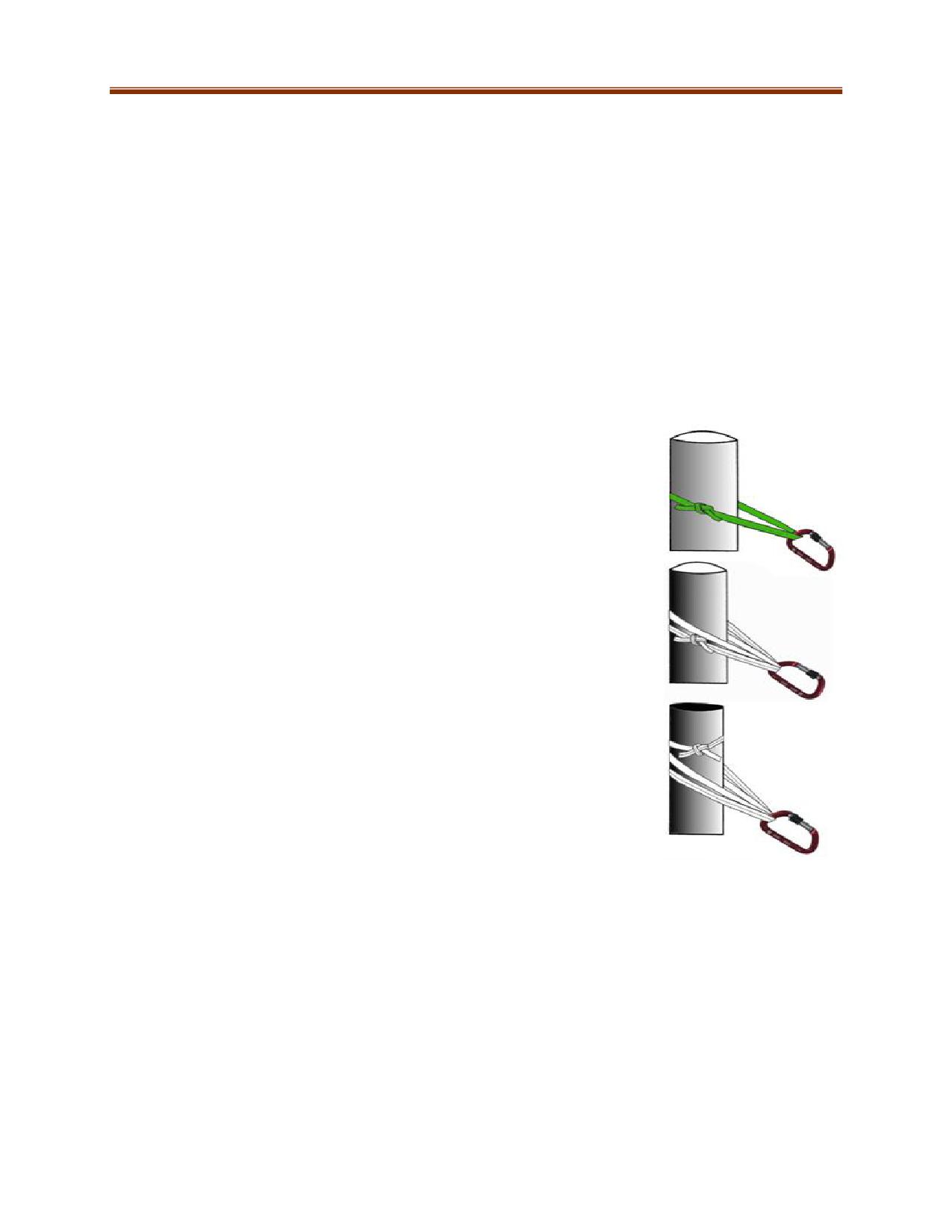
There may be cases where there is only a single bombproof anchor to use. When this happens, separate
attachment points must be put in place. (Example: Two independent webbing wraps with their own
separate connection points. Another method is to use a rated manufactured multi-anchor point plate.)
Anchor attachment points can be extended from the bombproof anchor to a more favourable location
for rigging. An example of this is adding an extension and making the anchor attachment point more
accessible for rescuers working around the edge of a fall area. The rescuers can then connect their
harness in the extended anchor point for fall protection or fall restraint.
Rope Anchor Attachments
Figure 8 follow through with a Figure 8 on a Bight: Requires three feet of rope plus length needed to
wrap around anchor. The Figure 8 on a Bight is the working end.
Tensionless hitch: Used on cylinder shaped anchors. Rope is wrapped three or more times. The anchor
should be at least 10 times the rope’s diameter. Use a figure of eight on a bight with a carabiner or a
figure eight follow through to secure the loose end of the rope.
Simple Slung (Single Loop)
Wrap a single strand of webbing around an anchor and join the ends with a
ring bend. The ring bend will be extremely difficult to untie once loaded.
When the internal angle of the sling legs is less than 90°, it can bear forces as
high as 22 kN, which is only suitable for a single person load
Basket Hitch
Keep the angle between the legs to less than 45°. Any greater angle may
result in the carabiner being side-loaded. Not recommend for use where the
direction of pull is changing because the legs of the hitch will not load evenly.
This will significantly reduce its strength. It is suitable for a two-person or
rescue-size load.
Wrap-3-Pull-2
Wrap-3-Pull-2 is an anchor attachment that can be tied with webbing. Very
little strength is lost when tied properly with the tied ends of the webbing
facing the load and against the anchor.
Advantages
Allows carabiner to slide around equalize to avoid side loading.
When tensioned, it cinches on to the tree to allow secure placement of high-point directional
pulleys.
Tying
1. Wrap three times around the anchor point.
2. Tie the long leg with an overhand trace back with the short leg to create a ring bend.
3. Position load side against the anchor point.
4. Pull the two unknotted loops forward and clip with a carabiner.
11-39
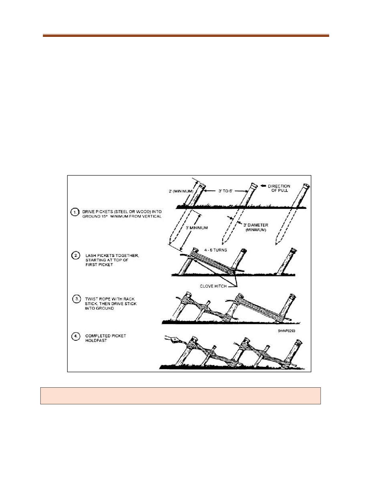
Picket Anchor Systems
The picket system is one alternative when no anchors are available in a wilderness area. However, picket
systems require a great deal of time to prepare for rescue use.
Picket System Set-Up
1. The pickets should be 1 in (2.5 cm) diameter and have a length of 4-5 ft (1.2-1.5 m), so that
there will be a minimum of 2/3 of the length in the ground.
2. Drive the pickets at an angle of 15 degrees away from the force to be anchored.
3. Connect the pickets in each row together by lashing from the top of the first picket (the one
closest to the load with a clove hitch) to the bottom of the next picket three to four times
and tie off at base. Continue in this manner until all rows of pickets are lashed together. Use
12.7-mm (1/2 in) rope or webbing approximately 50 ft (15 m) long.
4. Tension the lashings by twisting with a stick four to six turns. Drive this stick into the ground
to secure it.
5. Connect the main line by clipping it to the front picket in each row.
Multiple anchor points may be required to establish a bombproof anchor. Remember the 10:1
safety factor.
11-40
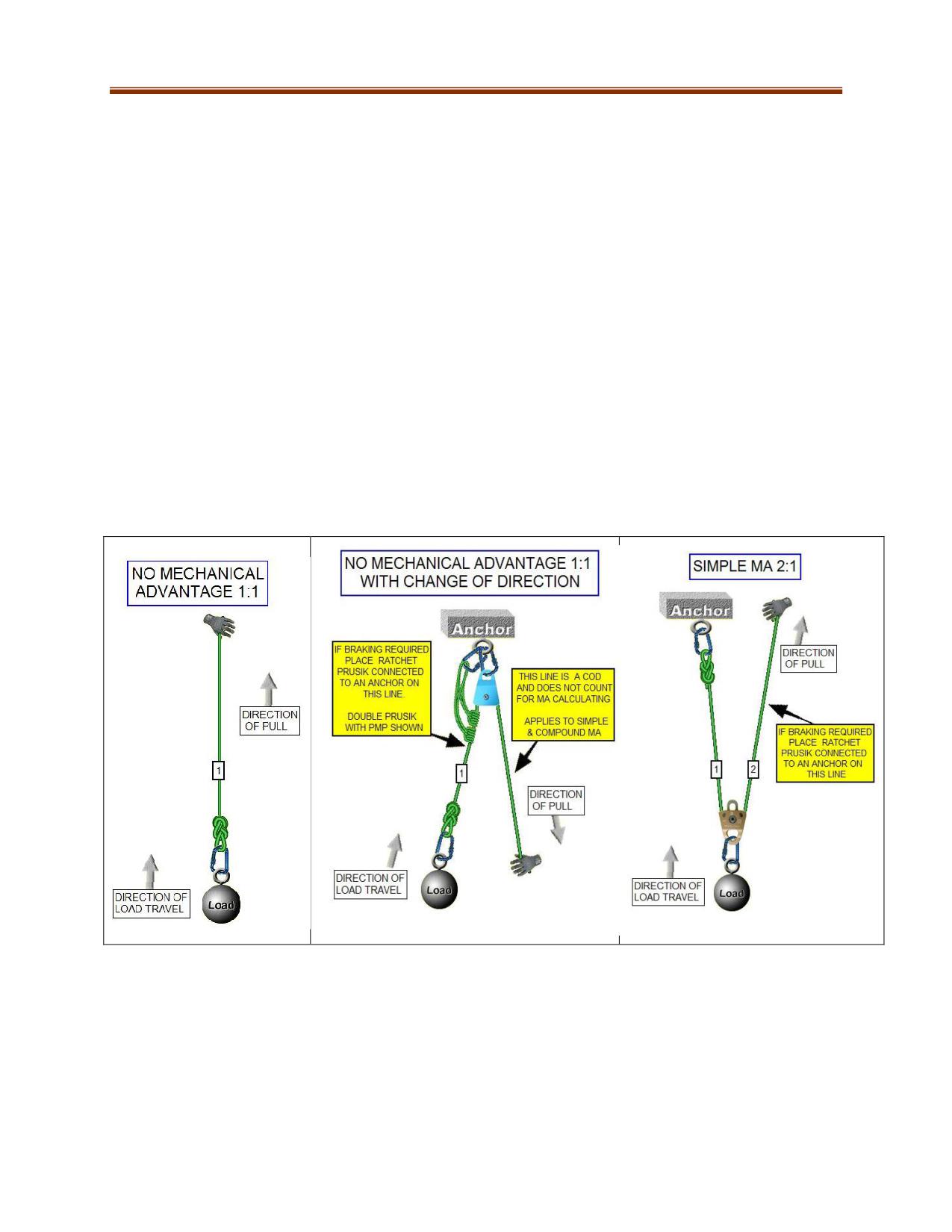
MECHANICAL ADVANTAGES
Mechanical advantages (MA) are built by the use of pulleys and ropes. They are used in rescue
operations where a load needs to be lifted. MA pulley systems assist in raising loads by reducing the
amount of force needed. For example, a system with a MA of 5:1 requires only a fifth of the force used
in a 1:1 system. This MA will require five times more length of rope to be pulled (pulling a rope five
metres in a 5:1 pulley system will move the load one metre).
Simple systems use ropes attached directly to the load or anchor while the other end of the rope is
where to apply the force to move the load.
The MA will always be an odd number when the rope is tied to the load. It will be even when
tied to the anchor.
An easy method to determine the MA of a simple pulley system to count how many ropes are
used in the system. Note: If the final rope is being pulled in the opposite direction of the load
travel, it is considered a change of direction and is not counted toward the calculation of the
total MA.
Make certain that pulleys are aligned and avoid having a rope crossover within the MA causing
friction or twisting. Simple systems with a MA of more than 5:1 are more likely to encounter this
problem and should be avoided if possible. In these circumstances consider a compound system.
11-41
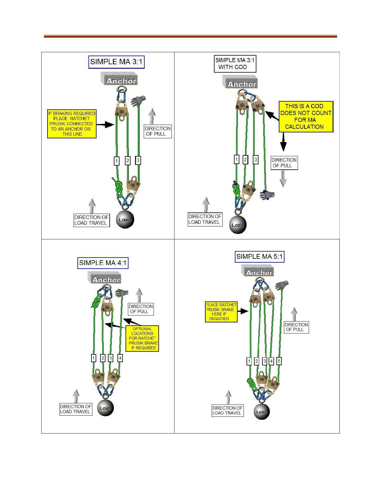
11-42
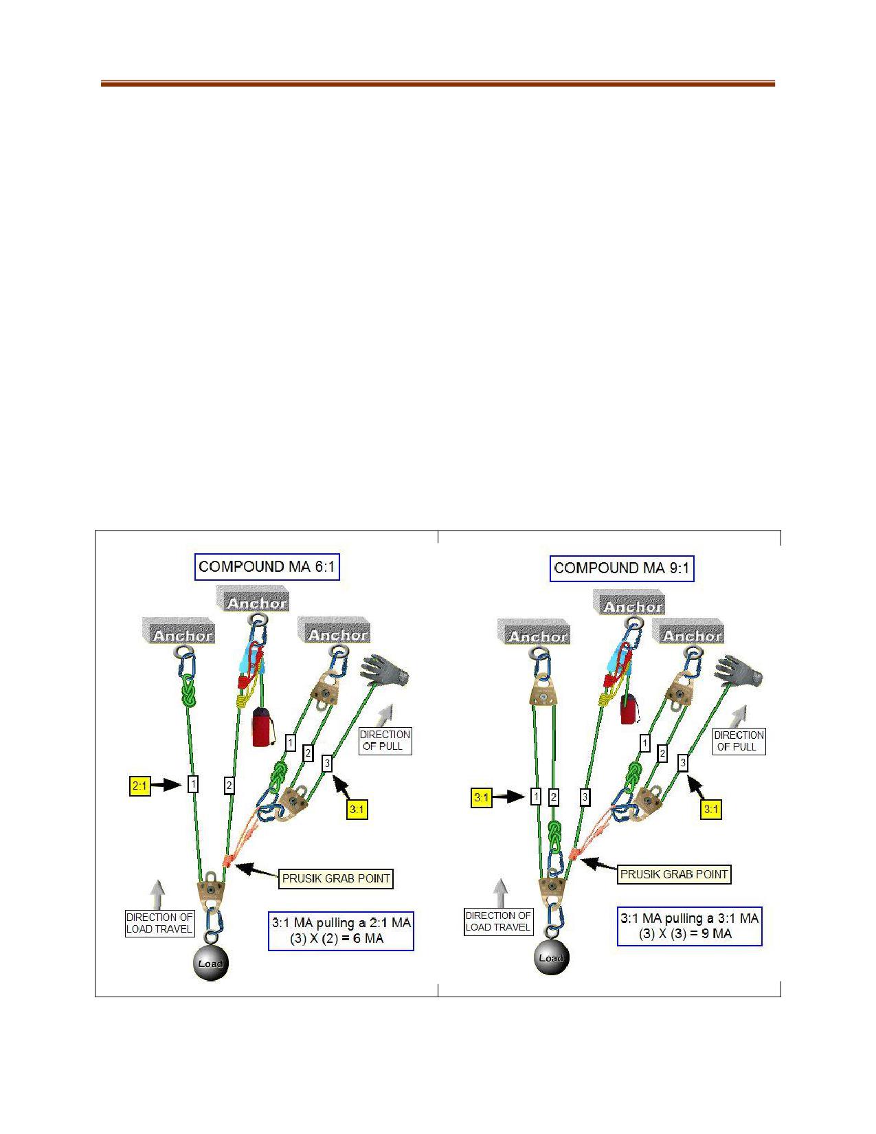
Prusiks
The prusik grab point (or haul prusik) is the prusik wrap that attaches one MA to another in compound
systems and allows one to pull the other. Placed in a Z-Rig, it allows a mechanical advantage to pull on
itself (same rope). It is the component that slides for a reset when the pulleys become chocked (too
close together). Only one prusik of 8mm or 9mm is used for this operation. A slipping prusik is a good
indicator of excessive forces being applied in the system. Some mechanical rope grab devices can cause
damage to rope, if using manufacturer procedures must be followed.
A ratchet prusik is placed in a haul system to safely hold a load (park brake) while resetting the pulling
mechanical advantage in compound and Z-Rig setups. It also acts as a safety on the haul line. For large
loads (> one person 300 lbs (136 kg)), use tandem prusiks. Adding a prusik minding pulley allows the
prusiks on the haul line to operate the same as a Tandem Prusik Safety Belay when raising a load. There
are commercial devices available that provide the same functions of this rigging.
Compound systems add a second or more pulley systems to the first pulley system (MA pulling a MA).
To determine the MA of a compound system, multiply the MA of the two systems to determine
the total MA. E.g., if one system is 3:1 and the other is 2:1, the total MA is 6:1 (3x2).
If resetting a compound pulley system in which the two systems have different Mas, attach the
system with a lower MA to the load and pull this with the higher MA. In some circumstances this
rule of thumb will not work for the task at hand.
Ideally separate anchors are used for each MA, spread apart by a metre or more.
11-43
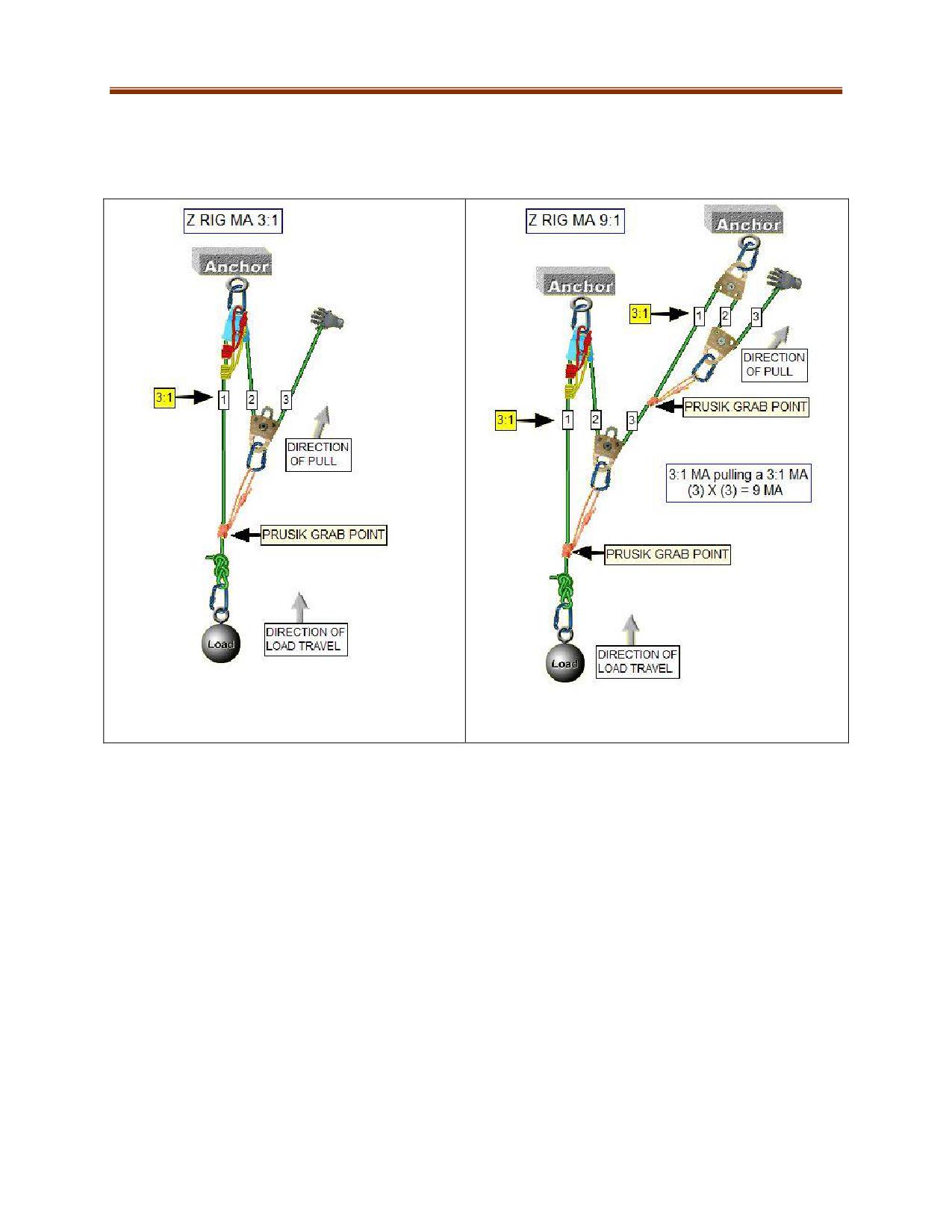
Z-Rig Mechanical Advantage Systems
Z-Rigs are used extensively in rope rescue systems. A Z-Rig MA is a 3:1 MA made with a single rope and
can easily be changed to a higher MA. The Z-rig gets its name from the shape it forms when constructed.
11-44
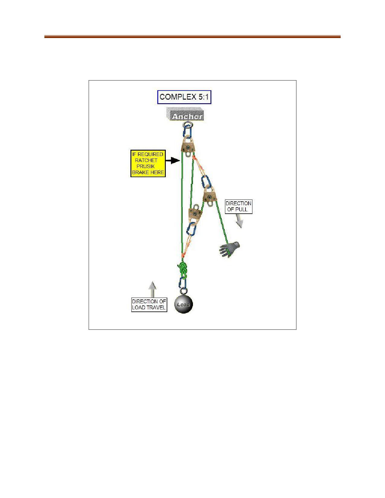
Complex Mechanical Advantage Systems
A complex MA system involves combining two simple MA systems so that the travelling pulleys collapse
together. The main advantage of complex systems is that they need less equipment to accomplish a
larger MA.
11-45
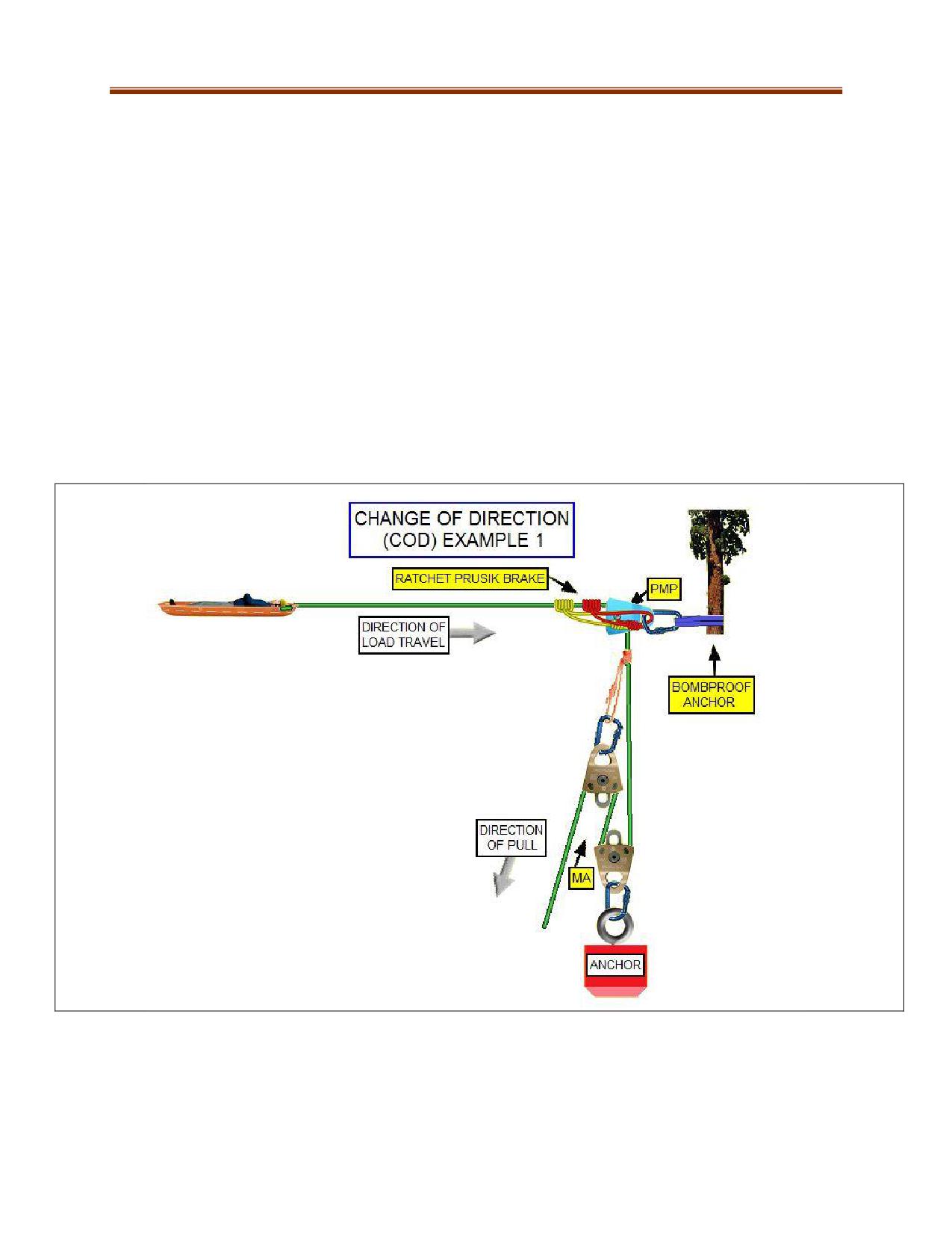
Change of Direction
A change of direction (COD) within a MA is where the pulling force on the rope end is traveling in the
opposite direction of the load travel. Example: Pulling downwards on a MA while the load is traveling
upwards.
In some rope rigging situations, a COD pulley on a separate bombproof anchor might be required. (If the
distance between a highpoint COD and the ground creates a drop high enough to cause harm, then the
rigging should be run at ground level.)
Examples of when to use a COD:
Structural situations where a COD is needed because of limited space to rig
Situations where the main anchor point causes the haul line to not align with the load
For embankment-type rescues where MA hauling and reset distances are limited
Using building support beams as High Directional Anchor (HDA)
Rigging for a cliff or severe edge where a high point is needed, such as on an A frame.
11-46
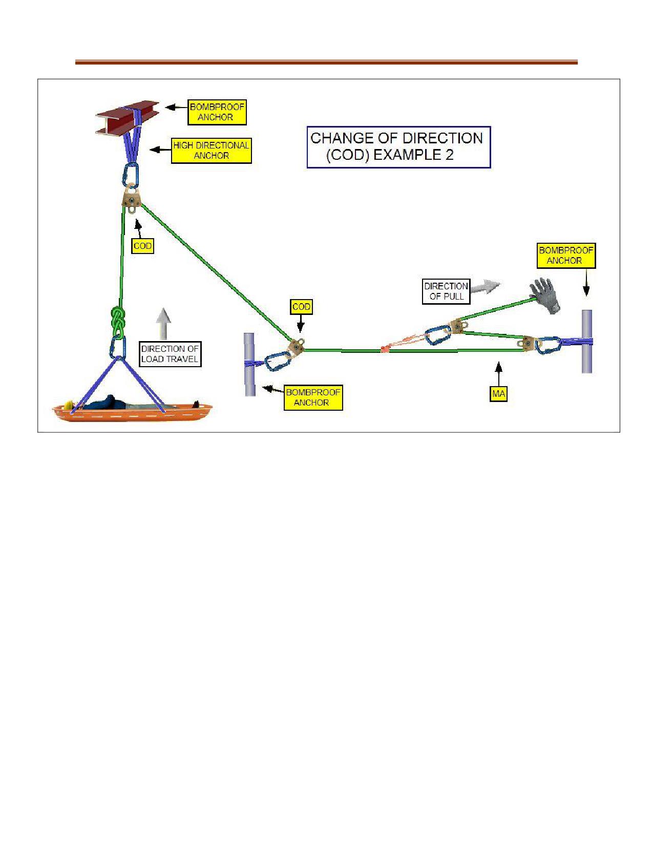
Large Mechanical Advantage Systems
Most rescues can be accomplished with a 6:1 pulley system. 8:1 and 9:1 systems are generally not
recommended because of the amount of rope and space required. They also have less “feel” for the
load being pulled, leading to too much force being exerted and potentially damaging the system. Safe
working loads of rigging equipment must be considered in terms of force applied by these larger MAs.
Rescuer Pulling Force
The average rescuer can pull with a maximum force of 23 kg (55 lbs). Before using a pulley system,
calculate roughly how much force will be exerted by the rescuers and the MA. A prusik will slip at
around 500 kg (1100 lbs). Rescuers need to do a system check and re-examine the load weight including
the pulling forces being applied when this occurs.
BELAYS
Belaying is used to protect a person or load from falling. Some methods are designed for light loads,
such as a single person. For heavier loads, rescuers use a safety belay system.
Munter Belay techniques can be used for a single person safety line on low-angle consolidated slope.
The advantage is quick setup in situations where a critical casualty requires immediate first aid.
11-47
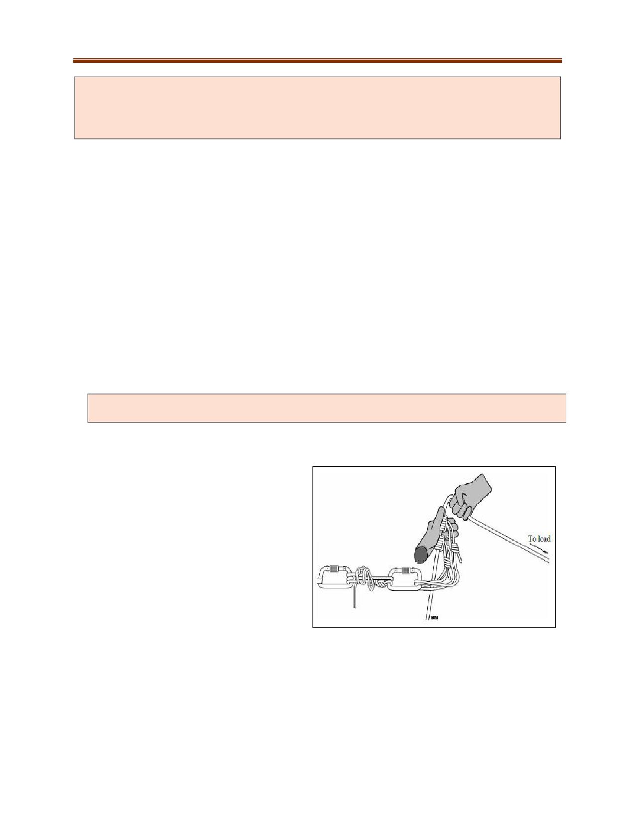
Munter belay techniques are not to be used for any technical rescue operations, such as high-
structural or cliff rescues, in which a serious fall could occur. These belay methods do not pass the
Whistle Test: If, in theory, at any point a whistle were blown that signals all personnel to stop and
remove their hands from the system, nothing catastrophic will occur to the live load.
Safety Belay Systems
Main rope rescue lines can fail due to equipment failure, human error or environmental conditions. The
best practice for mine rescue rope rigging is the use of a second independent rope system as a back-up
when lowering or raising loads.
Functions of a safety belay system:
Catches the load of the main line if it fails without an operator to engage it. Normally the safety
belay system should never come under tension unless there has been a failure. (Note: The use
of two-line systems with each line acting as both load and safety belay are used in some rescue
operations. This technique requires specific training and is not included in this manual.)
Must be able to survive the event sufficiently undamaged and allow load to move up or down.
The Maximum Arrest Force (MAF) must not cause injury to the rescuer or casualty, nor may it
cause a system failure such as pulling out an anchor or cutting the rope on an edge.
The stopping distance must be short enough to prevent the load from hitting obstacles.
Must work in any environment.
Rescuers must be able to operate the load under tension after it has been engaged with a load-
releasing hitch.
A variety of belaying equipment is commercially available. If any equipment used is not
mentioned in this manual, please follow the manufacturer’s recommendations to avoid misuse.
Belay Operation
1. The Prusiks should be held together in
one hand in a thumbless grip (belay
hand), to facilitate releasing. The thumb
does not wrap around the Prusiks.
2. The hand should be held thumb up and
with the opening towards the load by
twisting the wrist. This wrist-twisting
allows the belayer to monitor the
amount of slack in the belay rope so that
it can be kept to a minimum without the
Prusiks accidentally grabbing. It also
positions the Prusiks 90° to the direction of the belay line which aids in their ability to grab.
3. The second hand is used to pull the belay rope up through the Prusiks held in the belay hand.
4. Make sure the Prusiks remain snug on the rope through the operation.
11-48
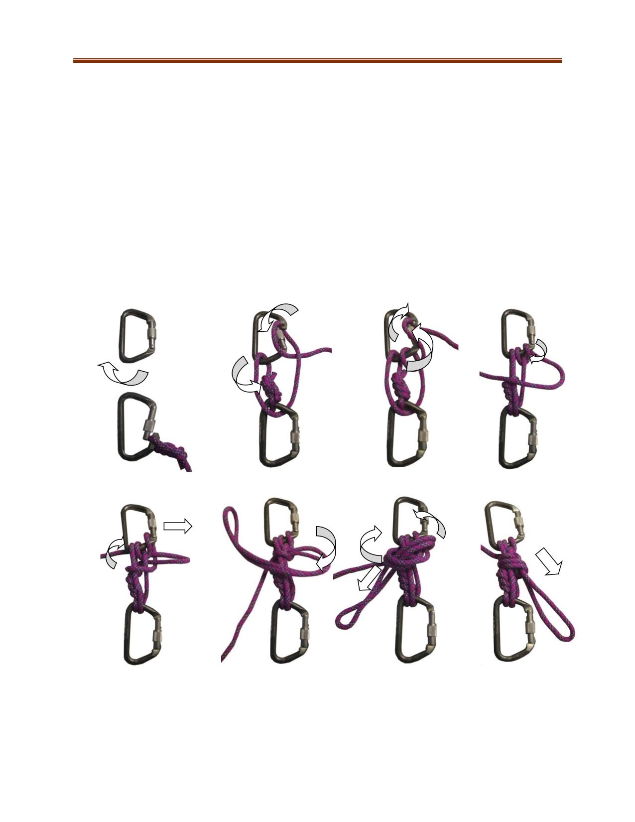
5. In the event of a failure of the load system the pull of the belay rope should snap the Prusiks out
of the operator’s hands and allow them to grab quickly and without the belayer having to do
anything.
Radium Release Hitch
The radium release hitch is designed for releasing loads on ropes such as jammed safety belay prusiks
and passing knots in the main line system during lowers. They are also used when you need to be able to
lower a leading-edge directional pulley to allow a load to pass.
Use two large locking 'D'-shaped carabiners and a 10-m length of 8-mm cordage.
1.
Place two carabiners on the ground with the gates facing right, claws facing the position of
function bottom down, top up.
2.
Tie a small figure eight-on-a-bight in one end of the cord and clip it into the load-side of the
carabiner.
3.
Wrap the top carbiner and then (3) back down through the load carabiner, then back up to the
anchor carabiner and incorporating a (4-5) Munter hitch on that carabiner on its gate side.
5
2
4
6
3
1
9
10
8
11.
13.
7
12.
4. Complete the Munter hitch wrap around all of the cordage strands (6-7). Pull a long loop
through the bight created (8), and snug this up tight against the Munter.
5. Ensure that the Munter hitch is in the release position with the in-feed rope on the gate side of
the carabiner. Secure with an overhand safety around the entire stem. (9-13)
11-49
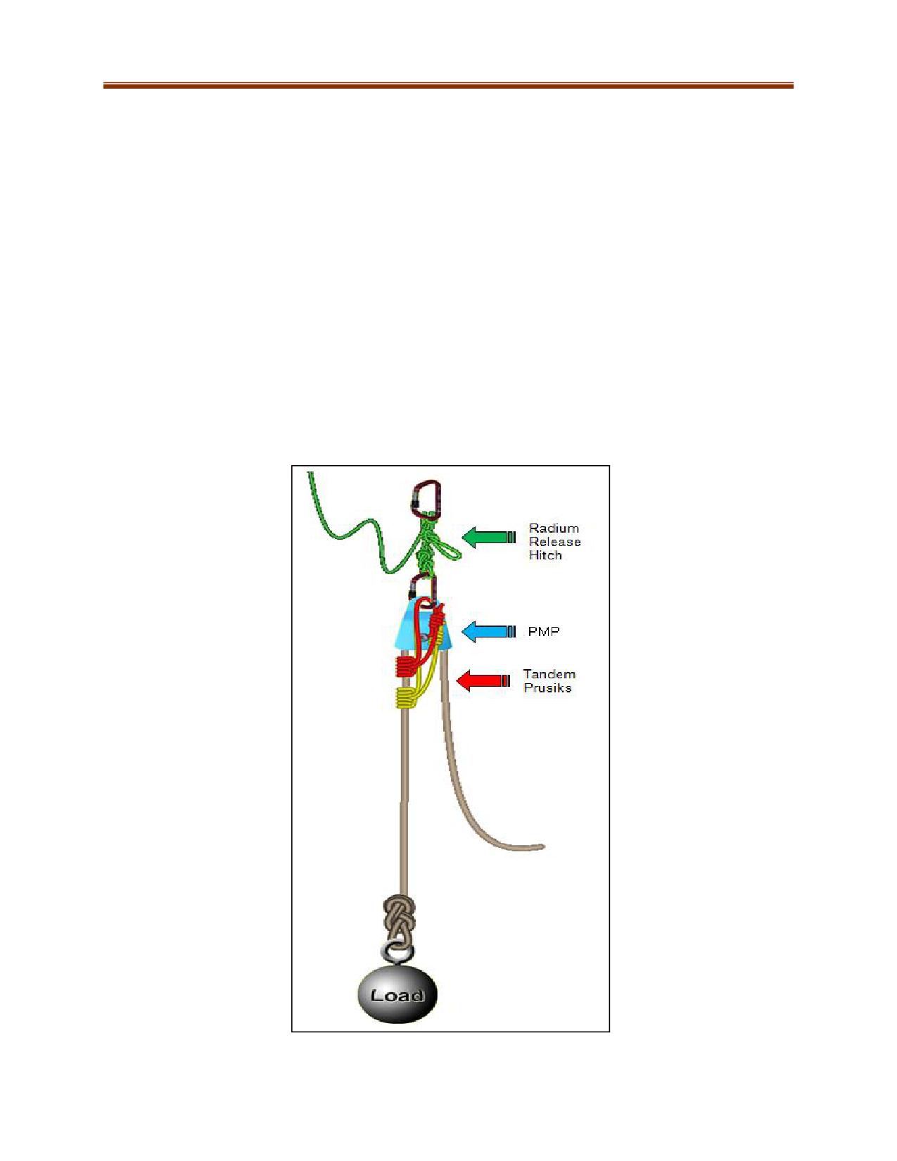
Tandem Prusik Safety Belay
The tandem prusik belay system is designed to capture rescue-size loads. It also incorporates a load
releasing hitch (Radium Release Hitch). A single prusik will slip if overly loaded and the spacing between
the wraps allows them both to work without interfering with each other.
Components of a Prusik Safety Belay
A Radium Release Hitch attached to the anchor attachment point. The Munter hitch is on the
anchor side
A Prusik Minding Pulley (PMP) attached to the release hitch. Note: Not required for a lowering
operation but very beneficial when retrieving, such as when raising rigging.
A short prusik approx. 5 ft (1.5 m) long and a long prusik approx. 6 ft (1.8 m) long attached to
load release connection and then both triple prusik wrapped around the belay rope. The shorter
prusik is set closer to the anchor with approximately two fingers to a hand-width of space
between its wraps and the second longer prusik wraps. Note: These lengths work well for 2-in
(5-cm) or 3-in (7.5-cm) PMPs.
11-50
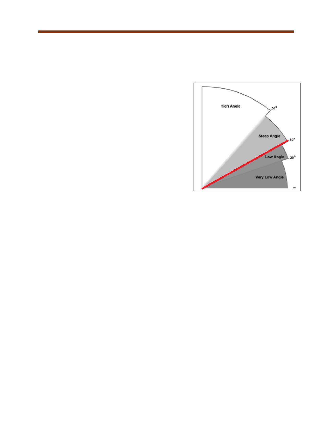
RAPPELLING
Rappelling is the act of descending a rope with the use of a descent control device operated by the
rescuer. There are many devices that can be used for this but most rescue teams use a “personal” brake
bar or micro rack. There are various other commercial devices designed for this application. The
descending device is connected to the rescuer’s harness with
a locking carabiner.
For mine rescue rappelling operations over 30-degree (steep
or high) angles, a safety belay line must be connected from a
separate bombproof anchor point to the rappelling rescuer’s
harness. The belay system must include tandem prusiks or an
approved commercial belay device.
Rescuers must be trained and competent in using the device
and be able to stop part way in the descent and able to either
use a tie-off procedure or a locking mechanism in some
devices. Dangerous errors include using an inappropriate
reeve of the rope on a brake bar and inserting rope in the
wrong direction in a commercial descent device.
Before Beginning a Rappelling Operation
Completely check anchors, rope systems, attachment points, carabiner locks, rescuers harness
and PPE.
Ensure rappel distance does not exceed rope length.
Connect the main line to the waist ‘D’ attachment. The belay is connected to the sternal (chest)
or dorsal (back) attachment depending on the situation.
Person assigned to operate and monitor the safety belay line must be ready to provide
appropriate slack throughout and remain with that task until the rappel has been completed.
Check that rescuers working near edges are on fall restraint or fall arrest rigging.
Add edge protection to prevent rope damage, look for sharp or loose edge materials such as
rocks and building flashings.
Check the surface of the face that the rescuer will travel along for hazards, ice, slippery wet,
loose materials, and snags.
Consider rope stretch on initial load on rappel line at transition point (edge).
Review rope angles. If a high anchor point is not available, the rappel person may have to crawl
over edge to get set rather than use the “stand and lean back” rappel procedure.
Check that the starting point is not directly over a hazard, casualty, or fellow rescuer.
Avoid creating the potential for swinging by starting too far away from the direct line (vertical
fall line) of rappel in relation to the anchor attachment point.
11-51
During Rappelling
Descending too fast can create problems such as high heat from friction or a loss of control by
rescuer.
Do not jump from side to side, as this can cause abrasions to the rope.
Rescuers’ leg stance depends on the type and shape of the footing surface. Good balance and
avoiding foot slippage is critical. In general, rescuers should attempt to place their feet a small
distance apart, approximately the same as shoulder width.
If there is a rescuer on the ground, they can take control of the descent by controlling tension
on the rappel rope from the bottom
Arriving at the Bottom
Bend knees slightly before stopping. Once down, stand upright.
Disconnect rappel devices from rope. Leaving them on may subject the device to heat damage
and there may be another rescuer that will be using this line.
Disconnect from safety belay line.
Notify Captain or rescue officer when off each line.
11-52
11-53
Western Canada Mine Rescue Manual
Chapter 12 Underground
Operations
12-1
OBJECTIVES
Underground mining rescue operations present unique challenges and corresponding tactics. Upon
completion of this chapter, the trainee shall be able to demonstrate knowledge of and/or competency
in:
Mine Emergency Response Plans (MERPs)
Principles of underground mine ventilation
Instruments used to measure mine ventilation
Mine plans and sections
Techniques used in underground firefighting
A GUIDE FOR PLANNING MINE EMERGENCY PROCEDURES
Safety
The primary goal of any mine rescue operation is to ensure the safety of the mine rescue team. Hazard
identification and control are key components in a rescue operation. Due to the nature of underground
operations, tactics such as controlling fire and ventilation may become a priority task to achieve the
mine rescue principles.
All mines are required to have a Mine Emergency Response Plan. Mine rescue teams need to be
familiar with all the content in the plan and all must follow all on-site emergency procedures. This
chapter is a guide to the components of an emergency response plan.
Emergency response system activation:
Initial Report of Emergency: Discovery of emergency is relayed to designated personnel.
Initiation of Mine Emergency Response Plan: Designated personnel receive the emergency
report and initiate the mine emergency response plan.
Notification systems: There are a variety of systems used to notify workers of an emergency,
such as stench gas, radios/telephones, personal emergency devices (PEDs), and other audio and
visual alarms.
Organizational chart showing chain of command
Role
Responsibilities
Mine Manager
All mine operations and incident response
Ensures effective MERP is in place
Liaises with jurisdictional authorities
Delegates command
Mine Superintendent
Knowledge of mine operations
Accountability system (e.g., tag-in, tag-out)
Liaison between mine manager and response
structure
Controls access to the mine
Plant/Maintenance
On-site support (e.g., electrical, mechanical,
Superintendent
ventilation, water etc.)
Chief Engineer
Mine plans and ventilation
Technical advice
12-2
Emergency Response
Relays directions and observations between
Co-ordinator
command centre and mine rescue teams
Rescue Teams
Respond within their capacity
/Specialists
Take direction from emergency response co-
ordinator and report back observations
Maintenance of response equipment
Medical Services
Deal with any casualties brought to the surface
Communicate directly with external medical
support (ambulances, medical doctors, etc.)
Communicate internally with command centre
Logistics and Support
All the services and support needs of an
incident (transportation, lodging, food, costs,
families, confidentiality and security)
All outside liaisons (media)
Obtains essential support personnel (Post-
incident critical stress counseling, etc.)
Maintains facilities, equipment and supplies
Escape routes and travelways: Both primary and secondary routes must be clearly marked on mine
plans and posted in strategic locations around the mine. These plans must be regularly updated and
readily available to mine rescue personnel.
Refuge stations: A place where workers can isolate themselves from toxic gases, smoke and oxygen-
deficient atmospheres. The locations and components of a refuge station are dictated by jurisdictional
regulations. They can be:
Portable: Are smaller and can be easily moved as production or development progresses.
Permanent: Can accommodate more people due to their larger size and available air. They may
become redundant as mine development progresses but still remain functional.
Workers and rescue teams must be familiar with:
Refuge station locations in the mine
Refuge station operating procedures
Capacity of refuge station
Equipment and furnishings, such as: Carbon dioxide absorbent, oxygen supply (cylinders or
generators), heater/air conditioning, fire extinguishers, lighting, first aid supplies and stretcher,
toilet facilities, sealing clay, etc.
Duration and conservation of supplies, such as oxygen/air, water, food, battery capacity, etc.
Communication procedures
Rule of Thumb: Approximately one cubic metre of air will provide sufficient oxygen for an
average person at rest for one hour. After one hour, the oxygen content will be approximately
16% and the carbon dioxide content will be approximately 5%.
Self-rescuer caches: These caches will be found in various locations around the mine and contain a
supply of self-rescuers. They are designed to assist escaping workers. They are also a resource to mine
rescue teams.
12-3
Ground conditions: Identify and control hazardous ground conditions using techniques such as:
Scaling: The sounding and removal of loose
Temporary ground support: Erecting timber supports or other devices
Barricading: Preventing access to areas that do not have adequate ground support
Ventilation: Rescuers need to understand normal mine ventilation and how it is affected by fire or
failures in ventilation control.
Power distribution, compressed air, and water distribution systems: Rescuers may be accessing these
systems in an emergency and must be familiar with their operation and isolation.
Emergency Egress Procedures: In the event that a worker reaches the surface during an emergency,
they must check out of the mine using the established accountability system. They should then
assemble in a designated area and should not leave until told to do so by a person in authority.
Command/Emergency Operations Group: Personnel designated under the mine emergency response
plan for the direction, coordination, communication, and support of the emergency response.
FIRE CONTROL AND VENTILATION
Underground mine fires are extremely hazardous situations with the potential for catastrophic loss of
life and damage to the mine workings. Fire suppression underground requires particular skills and a
solid understanding of the basic principles of mine ventilation. Even greater care is needed than in
the case of surface fires to avoid rescue workers becoming casualties themselves.
Underground Mine Ventilation
Underground mine ventilation is the primary engineering control used to provide respirable air and to
reduce workers’ exposure to hazardous atmospheres. Understanding mine ventilation will help mine
rescue teams to safely advance into the mine during an emergency.
Factors Affecting Air Movement in a Mine
Pressure: Horizontal air movements are caused by differences in air pressure. Air always moves from
a high-pressure area to an area of lower pressure. The greater the pressure difference, the faster the
air will move.
Relative Weight: A difference in relative weight (air = 1) also causes air to move, but movements caused
by differences in weight are in the vertical direction.
Temperature: Hot air is lighter than cold air and rises. Cold air is heavier and will sink to lower places.
12-4
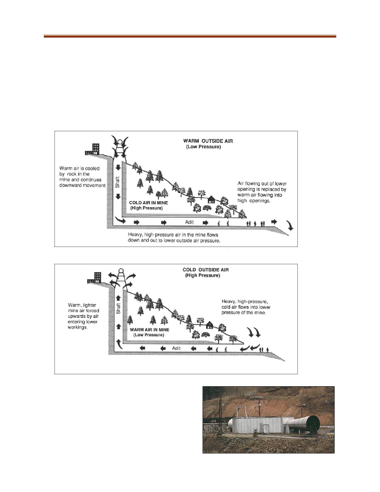
Air moves through a mine by two methods:
Natural Ventilation
Mechanical Ventilation
Natural Ventilation
Some mines, especially those in mountainous terrain, have natural ventilation caused by differences in
pressure inside and outside the mine and by differences in the relative weight of warm and cold air.
While all mines with operating diesel equipment are required to use mechanical ventilation, a basic
understanding of natural ventilation principles will assist in mine rescue operations.
Mechanical Ventilation
While natural mine ventilation can be very effective, it
is not reliable. Mechanical ventilation is required
when using internal combustion engines where a
specific volume of air is required. This is accomplished
by installing fans at mine openings or inside the mine.
Mine fans are simply a means of changing the air
pressure at specific points in the mine.
12-5
Positive pressure ventilation uses a fan to create a
high-pressure zone. In underground operations, this
is done by placing a fan at the entrance of a tunnel,
facing inwards. The high-pressure air in front of the
fan will flow to the lower pressure areas further
from the fan. The scooping action of the fan blades
prevents the air from flowing back through the fan.
Push pull ventilation involves combining a positive pressure fan and an exhaust fan to create a pressure
difference that will increase the air flow.
Auxiliary ventilation is used to direct air flows from the main ventilation route to dead-end headings.
fan
fan
Blowing Fan
Exhausting Fan
Air Distribution
Fig 12.1: Blowing and Exhausting fans providing auxiliary ventilation
As air flows through a mine it always takes the easiest path, that is, the path that offers the least
resistance. The resistance to air flow is determined by:
The amount of air passing
The roughness of the openings it is passing through (friction)
The size of the openings
The length of the openings
Air will pass much more easily through a large diameter, smooth-walled tunnel than it will through a
small diameter, heavily timbered tunnel. Restrictions in tunnels such as locomotives, trackless mining
equipment, conveyors, ventilation regulators, etc., will add to the resistance of a mine opening and
make it more difficult for air to pass.
12-6
Splits
When air flowing through a mine working comes to a place where it branches into two or more
openings, the air will split and some will flow through each opening. The amount that flows in each
direction will be determined by the effective resistance in each opening. Air will not flow into dead-
end drifts as it has nowhere to go.
The most common methods of routing air to where it is required are:
Ventilation stoppings and doors
Ventilation regulators
Auxiliary fans (Booster fans)
Auxiliary fans with ventilation ducting
Line brattices
Ventilation Stoppings and Doors
Ventilation stoppings and doors can be used to stop air from going where it is not wanted and forcing
it to go where it is needed. When main fans are installed in a mine, they are offset from the main mine
entrance. Airlocks are used to overcome the pressure created by the fans and to facilitate access and
egress. It is important that doors be kept in their proper positions so as not to interrupt or change
ventilation in the mine.
Solid stoppings (bulkheads) are used when access is not required; doors in bulkheads are used when
access is required. There are many ways in which stoppings and doors are used to route air
through mines. Their main function is to isolate high-pressure areas from low-pressure areas where air
is not required. A partially opened door can also be used for this purpose.
A regulator is a solid stopping with an adjustable opening in it. They are used to reduce the amount of
air passing through openings by increasing the amount of resistance. Doing so increases the amount of
air passing through other airways. Settings are not to be changed by unauthorized personnel.
Fire doors are used to control air flows in the event of mine fires and at such times they serve the same
purpose as stoppings or ventilation doors. Fire doors are often built at strategic locations in mines,
such as at shaft stations, shop areas, and fueling bases. In the event of fire they are closed so as to
isolate sections of the mine. If installed fire doors must be kept clear of obstructions and in working
condition at all times.
Auxiliary fans are often set in places where it is necessary to increase air pressure to force air through
workings that are otherwise difficult to ventilate. The auxiliary fan forces relatively large quantities of
fresh air through a drift where it carries dust and blasting smoke out to the ventilation exhaust system.
Line brattice is a partition made of Fabrine or burlap used to provide auxiliary ventilation. It is hung
from roof (back) to floor to create a second air path in a dead-end heading.
12-7
INSTRUMENTS USED IN VENTILATION WORK
A manometer is a U-shaped transparent tube partially filled with liquid
used to determine pressure differentials across a stopping or bulkhead
(wall of a refuge station). The difference in fluid height in a liquid column
manometer is proportional to the pressure difference.
An anemometer is used to measure air velocity. It consists of a small
fan that is rotated by the air current. The instrument is calibrated so
that each revolution of the vane corresponds to a unit of air travel.
A velometer is a small direct reading instrument used to measure the
velocity of air at a specific point. Pressure exerted on a vane travelling
in a circular tunnel causes a pointer to indicate the velocity of air moving
through mine workings. The following formula is used to calculate the
volume of air and its flow:
Volume Calculation
m
Heigℎt (m) × Widtℎ (m) × Velometer Reading (velocity
)
s
= Volume of Air (cubic metres per second)
E.g., 3 m x 5 m x 3 m/s = 45 m3 /s
Smoke tubes are used to measure low ventilation flows that cannot be
detected with a velometer or anemometer. They provide an indication of
air movement over distance. To determine the velocity, choose a set
distance (e.g., 50 m, 100 m) and measure the time it takes for the smoke
to travel that distance. Once that data is recorded, use the volume
calculation formula.
A barometer is an instrument used to measure the pressure of the
atmosphere. A rapid fall in the barometer indicates a decrease in the
atmospheric pressure that in turn decreases the mine ventilating
pressure. This would allow the gases in gobs and abandoned workings
to expand and flow into the active workings, creating a dangerous
condition.
12-8
MINE DRAWINGS
Maintaining up-to-date drawings of mine workings is essential for the day-to-day operation of a mine.
Drawings for use by mine rescue teams should show at a minimum the locations of shafts, travelways,
electrical systems, working places, refuge stations, and ventilation flows. This information is integral to
mine rescue response. Three types of mine drawings are commonly used:
Isometric drawings are three-dimensional pictures of the mine workings. It shows
what the workings would look like if all the rock surrounding the mine openings was
transparent. With the advent of trackless mining methods using inclined and spiral ramps,
normal mine drawings become quite difficult to read unless you are familiar with the mine
layout, whereas isometric drawings provide a quick overview.
12-9
Plan view mine drawings provide an overhead view of a mine. Mines will have separate plans
drawn for each level in the mine. They are drawn at various scales and the scale will always be
noted on the drawing. A legend will be included to indicate the symbols used for fans, ventilation
doors, shafts, raises, ore passes and so on. The symbols may vary from mine to mine.
Mines with large vertical dimensions require the use of sectional views to obtain a good
representation of the mine layout. A section can be thought of as a vertical plan. Mines may
have one very long dimension and one short dimension, resulting in the use of two kinds of
sections: longitudinal sections along the long dimension and cross-sections across the shorter
dimension (the width of the ore body).
12-10

UNDERGROUND MINE FIRES - CONTROL AND SUPPRESSION
Underground rescue workers must have a basic knowledge of the chemistry and behaviour of fire.
Underground fires are classified in the same way as fires on surface and progress through the same four
phases. Firefighting techniques are similar but have been adapted to take into account the unique
conditions present underground.
Methods
Direct Attacks are employed in the early stages of a fire by using agents such as water (hose lines),
foam, fire extinguishers, rock dust or sand. Unless a fire can be put out within a few hours by direct
attack, teams use an indirect method. Note: Rescuers must be aware of the hazards of water on super-
heated rock (loose or spalling), electricity, steam conversion, and catastrophic failure of tires.
Indirect Attacks are used when a fire poses too many hazards to rescue teams to combat directly and
only after all personnel in the mine have been accounted for. Methods include:
Sealing
Flooding with water
Smothering with high-expansion foam, silt, fill, other solids or inert gas
The decision to use an indirect attack can only be made by on-site incident command.
Sealing
Mine fires should be sealed when progress cannot be made by fighting them directly or when other
conditions, such as inaccessibility or probable dangerous accumulations of explosive gas, make sealing
advisable. Seals should be built on the intake and exhaust sides simultaneously. If this is not possible,
the seal on the fresh air side should be put up first.
If the exhaust side is sealed first, the rescue team will be in danger from the extremely toxic and hot
atmosphere. The team will also face the danger of an explosion caused by explosive gases backing up
over the seat of the fire.
Stoppings should be set at an adequate distance in the opening and as close to the fire as safety permits.
Allow enough room for a secondary seal. All ground in the vicinity of the stopping must be well checked
and scaled down.
After sealing is complete, all non-mine rescue personnel must immediately leave the fire area until it is
safe to return. If workers have been trapped in the mine, mine rescue teams must focus on rescuing
them as soon as practical.
Temporary seals are erected in an effort to quickly exclude most of
the air from a fire and are later supplemented by airtight permanent
seals. Common types of temporary stoppings or seals include:
Brattice, engineered fabric, or heavy-gauge plastic
Sandbags
Lumber
12-11

Commercially available inflatable bulkheads
Permanent seals are constructed after erecting temporary seals, and should be built
of heavy construction material strong enough to withstand an explosion, pressure, or
crushing, such as:
Brick
Concrete
Steel
Shotcrete
Flooding with water
Flooding an enclosed area of a mine with water is another way to deal with an out-of-control fire.
Flooding is only performed as a last resort because it makes any later recovery work difficult in that
area.
Deciding to Seal a Mine Fire
There are no set rules for sealing mine fires. It is the duty of the rescue teams to collect as much
information as possible about the fire and to relay this information to the emergency operations centre.
In turn, it is the duty of emergency operations centre to evaluate the information and decide whether to
seal the fire or continue to search for trapped or missing persons, but they must consider the welfare
and the safety of the rescue teams at all times.
Deciding to Unseal a Mine Fire
No attempts should be made to unseal a mine fire until:
Oxygen content of the sealed atmosphere is low enough to eliminate the possibility of
explosions
Carbon monoxide (indicator of combustion) has been reduced to a safe level, and
The temperature has cooled down well below the point of ignition
Gas tests of the atmosphere behind the stoppings should be taken at reasonable intervals as
determined by the Emergency Operations Centre. Gas tests should be taken through the seal with as
little disturbance as possible to the seal. Mine rescue teams testing gas levels must wear SCBAs.
Smothering
High-expansion foam removes two legs of the fire triangle:
oxygen and heat. The foam smothers and cools the fire at the
same time. However, smothering foam can only be used to fight
Class A and B fires. It is most commonly used in controlling fires
that cannot be approached at a close range.
Teams should not travel through foam-filled areas because the
foam can lead to difficulty hearing, blocked vision, and slick
surfaces. Teams should clear the foam as much as possible, such
as by using a water fog stream.
Steam conversion in high-expansion foam may result in dangerously low oxygen levels.
12-12
Silt, fill, or other solids can be used to smother a fire as well, but these materials can severely complicate
recovery of the affected section of the mine. Inert gases, such as carbon dioxide or nitrogen, can also be
used to smother a fire.
Rescue Team Responses to Underground Mining Hazards
Dust or gas explosions
Spontaneous combustion (underground coal mines)
Ground failure
Ground conditions (loose)
Inundation by water or hazardous atmosphere
Catastrophic mechanical or electrical failure
The primary roles of the rescue team responding to a suspected hazard are to ensure team safety,
remove or protect workers, explore the aftermath, and assess conditions. Once this is completed, the
teams will begin the process of rehabilitating the mine. The rehabilitation process includes re-
establishing:
Mine openings and safe travelways
Ventilation systems
Mechanical and electrical services
Communications
12-13
12-14
Western Canada Mine Rescue Manual
Chapter 13 Operations Skills
13-1
OBJECTIVES
This chapter provides basic guidelines for specific rescue operations skills. Upon completion of this
chapter, the trainee shall be able to demonstrate knowledge of and/or competency in:
Use of Portable Fire Extinguisher
Structural Search and Rescue
Casualty Management
Rescue from Vehicles and Mobile Equipment
o Stabilizing vehicles
o Access
Supplementary Mine Rescue Response Training
USE OF PORTABLE FIRE EXTINGUISHERS
Knowing how to use a fire extinguisher is a key component of emergency response. It would be
impossible to simulate every fire that may be encountered, as many other risks and hazards may be
present. The following basic steps will work for most fires:
1. Determine the class, size, and phase of the fire. Select the extinguisher accordingly.
2. Quickly check the extinguisher before attempting to use it. Look for significant external damage.
3. Prepare the extinguisher, pull out the pin, or pressurize the cartridge type before approaching
the fire.
4. Perform a quick test by activating trigger to determine functionality and wind direction if
applicable.
5. Approach the fire from the upwind side (wind at your back), monitor wind change, and adapt if
necessary.
6. Advance slowly and maintain a safe distance from the fire at all times.
7. Aim the nozzle at the base of the fire.
8. Squeeze the nozzle trigger to discharge.
9. Use a rapid sweeping motion to ensure the extinguishing agent reaches the base of the fire.
10. Overlap the flame edge of the fire.
11. Ensure the fire is extinguished.
12. Do not turn your back on a fire. Slowly back away and be prepared for re-ignition.
13. Set a fire watch.
Certain fires and conditions may require specific techniques, such as extinguishing ignited
pressurized gas vapour.
SEARCH AND RESCUE
Structural search and rescue involves entering a building experiencing hazardous conditions to ensure
the safety of those inside. The purpose of structural search and rescue is to:
Locate and remove trapped occupants
Locate hazards (e.g., seat of the fire, fire extension, sources of toxic atmosphere)
Identify and apply controls (ventilation, close doors/windows, fire suppression)
13-2
Structural entry
Identify and establish access and egress points
Identify hazards (check doors, windows for heat, smoke, signage, contents)
Gaining access through doors, windows, walls, forcible entry
Basic door entry
Rescuers will encounter closed doors during their searches. Before entering any structure or room,
rescuers must:
Check door, knobs/handles and hinges for heat and thermal line
Observe and assess for any smoke/fire
Determine entry by the direction in which the door swings. Keep low, open the door slowly,
and be aware of the potential for backdraft.
Interior search and rescue
Primary searches are conducted in the most critical areas first.
Secondary searches are conducted after initial fire suppression/ventilation.
Both searches follow a systematic search pattern. For example, the left- or right-handed search.
STANDARD SEARCH PROCEDURE
Mine rescue teams must follow certain protocols and procedures so that they can respond to
emergencies as efficiently and safely as possible. Search teams are a fundamental part of these
procedures. Teams consist of:
A minimum of two personnel
A rapid intervention team (RIT or back-up) on standby, established before entry
Equipment (hand light, gas detection equipment, breathing apparatus, entry tool, thermal
imaging camera if available)
Fig 13-1: Standard
search procedure for
one- and two-search
team arrangements
13-3
The Primary Search is a rapid, systematic
search of the following:
Most severely threatened areas
Area with largest number of
casualties
Remainder of hazard zone
Extension exposures
Secondary searches are thorough,
systematic searches that ensure the entire
structure is free of casualties and hazards.
When possible, different personnel from
those who performed the primary search
should be used so that new sets of eyes can
Fig 13-2: Areas to cover in the primary search, in priority order
assess the scene.
Search patterns ensure that rescuers do not get lost or
disoriented during a search. The team captain will determine
which direction to use (left or right hand) prior to entering a
structure. Search patterns will follow the walls until they return
to the starting point. If rescuers keep turning in the original
direction as they go in and out of rooms and arrive at the entry
point, they have completed a search.
If rescuers encounter a casualty or a problem during
the search, they must reverse the direction they used
upon entry to exit the structure.
While performing the search, rescuers must maintain
visual, tactile, or verbal communication to keep track of
each other.
Team members can extend their reach by using tools.
How rescuers move will depend on the conditions found in
the search area. For example, in smoke conditions,
rescuers would crawl and move cautiously.
Areas to be searched
Bathrooms, closets, and the spaces behind and under
furniture should be checked.
Check areas near windows for casualties overcome while
attempting to reach a window.
Indicating that a room has been searched
Close the door
Indicate the room has been searched. Some examples are:
o Mark an “x” on the door
o If unable to close the door, place a chair behind the door so that the legs are pointing
outwards
o Communicate to command that a room has been searched
13-4
CASUALTY MANAGEMENT
Locating, retrieving, and tending to casualties is the second fundamental principal of mine rescue
operations. There are three types of casualties:
Casualties already outside the hazard area
o These casualties must be accounted for, given medical treatment as required, and
removed to a safe zone
Casualties attempting to leave the hazard area
o These casualties must be secured, warned of hazards, and directed to safety
Casualties trapped, unconscious, or otherwise unable to leave the hazard area
o Rescuers will prioritize according to primary search principles
Injured casualties should not be moved before treatment is provided unless there is an immediate
danger to the casualty or rescue team. Triage, a system of priority-based casualty management, is an
essential component of multiple-casualty incidents.
EXTRICATION FROM VEHICLES AND EQUIPMENT
This section provides an overview for rescuing casualties trapped in vehicles. The skills below can also be
applied to extrication from stationary equipment. Prior to any work being done, hazards must be
identified and controlled.
Rescuers should never place themselves in a pinch point or danger zone while stabilizing. They must
also be aware of vehicle airbags that have not deployed during a motor vehicle incident.
After size up but before any other extrication activities, rescuers must stabilize the vehicle(s) and isolate
potential energy sources, such as a raised box or boom. Stabilization is the process of providing
additional support between an entrapping object (e.g., a vehicle) and the ground or other solid anchor
points to prevent unwanted movement. This ensures the safety of the rescuers and prevents further
injury to the casualties.
Vehicles should be stabilized to prevent both vertical and horizontal movement. Stabilization can be
achieved using lifting bags, wood, tie down straps, ropes, jacks, cribbing, wheel chocks, or other
specialized equipment.
Gaining Access
Access to a casualty can be gained through:
A normal operating door
A window
Removing parts or sections of the vehicle body
Shut Down Electrical Systems
Rescuers must shut down all electrical systems within the vehicle to prevent complications such as
movement and combustion. The main components are:
Lock out/Isolation points
Disconnecting batteries
Removing keys from ignition
13-5
Casualty Protection and Removal
It is critical to protect, monitor, and communicate with the casualty throughout the extrication. The
guiding principle for extrication is to remove the vehicle from around the casualty.
Extrication can be accomplished with basic hand tools or power tools. Rescuers should be trained in the
proper operation of the available tools.
Casualties must be properly packaged before extrication unless their lives are in immediate danger.
SUPPLEMENTARY RESCUE TECHNIQUES
Supplemental training is needed to respond to various rescue situations, as identified by site-specific
hazard identification procedures. These skills are beyond the scope of this manual. Some of these skills
are listed below:
Communications/command structure
Forcible Entry
Fast water and ice rescue
Vehicle extrication
Avalanche response
Heavy equipment operation
Confined spaces/hazardous
Underground emergency operations
atmospheres
Environmental (wildland fires) and
Hazardous materials/nuclear response
wildlife
Blasting procedures
Aircraft rescue and firefighting
Technical rope rescue
Site-specific fire response
Fall protection
Structural firefighting
Collapsed buildings and cave-ins
Wilderness search and rescue
13-6