Caterpillar. Dealer service tools catalog (2018) - page 11
Engine Tools
ENGINE LIFTING AND POSITIONING
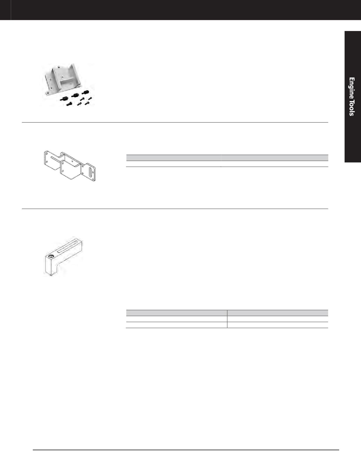
Engine Adapter Plates for 1U-5750
Warranty: Manufacturer’s
• Order only adapters needed for engines
NOTE: Products are shipped F.O.B. Searcy,
being worked on; universal adapter assembly
Arkansas. Each Engine mounting plate includes
required for mounting all but John Deere
all the necessary hardware and an engine
adapters to stand
application chart.
Engine Mounting Adapter
Model Usage: CT660 Truck
• Adapter for 1U-5750 Diesel Engine Repair
Specifications
Stand
Warranty: Manufacturer’s
• Dimensions: 26.85 x 18.25 x 11.5 in
• Weight: 70 lbs
Part Number
Description
374-6393
Engine Mounting Adapter
Transmission Support Bracket
Model Usage: 924G, 928G, 938G and 938H
• Used to mount transmission to an engine
• Width: 40 mm
Medium Wheel Loader
repair stand
• Weight: 3.065 kg
Warranty: None
• Used with 1U-5750 Engine Repair Stand
• Threaded Bolt: M16
• Tool is equipped with shoulder bolt that is
456-0652 Specifications
secured in place with a removable snap ring
• Length: 203.2 mm
Reference
• Height: 90 mm
• Service Manual, 924G and 928G Power Train
• Width: 40 mm
Disassembly and Assembly
• Weight: 3.74 kg
452-8986 Specifications
• Threaded Bolt: M12
• Length: 203.2 mm
• Height: 100 mm
Part Number
Description
452-8986
Transmission Support Bracket
456-0652
Transmission Support Bracket
JULY 2018 Engine Tools
3-271
Engine Tools
ENGINE LIFTING AND POSITIONING
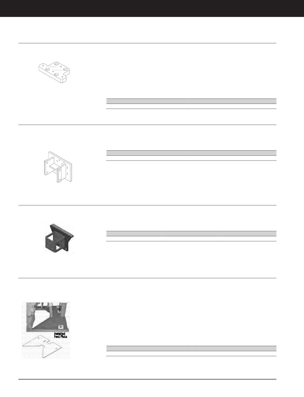
Transmission Adapter
Model Usage: CX28, CX31, CX35 Transmissions
• Mounts transmissions to engine repair stand
• KENR8128, CX35-P800 Petroleum
Transmission and Petroleum Power Train
Warranty: none
• Used with 1U-5750 Engine Repair Stand
Packages, Disassembly and Assembly
• Supports transmission during disassembly and
• KENR5098, CX28 On-Highway Transmission,
assembly
Disassembly and Assembly
References
• KENR8152, CX31-P600 Petroleum
Transmission Well Servicing
Part Number
Description
350-4401
Transmission Adapter
Repair Bracket Assembly
Essential Tool
• Used to mount C-9 Engine on 1U-5750 Diesel
• Attaches in place of crankcase breather cover
Engine Repair Stand
(breather cover must first be removed)
Model Usage: C-9 Engine
• Allows engine to be rotated 360 degrees
Warranty: Caterpillar ®Six Months
Part Number
Description
173-5533
Engine Stand Bracket
Bracket Assembly
Model Usage: C6.6
• Supports engine block during disassembly and
• Attaches in place of crankcase breather cover
assembly
(breather cover must first be removed)
Warranty: Caterpillar ®Six Months
• Allows engine to be rotated as needed
Part Number
Dimensions
Weight
351-0236
400 x 283 x 257 mm
23 kg (50.7 lb)
Foot Plate
Model Usage: 1U-5750 Rollover Stand
• Used to provide a place for operator to stand
Installation Instructions
and/or a place for tools or parts
Warranty: Caterpillar ®Six Months
1.
Installs without disassembling rollover
• Used with 1U-5750 Engine Repair Stand
stand.
• Enhances usability of rollover stand
2.
Parking brake pins must be unscrewed and
reinstalled when positioning plate.
• Specially shaped to fill in space between
hydraulic jack and end post
• Coated with anti-skid material and painted
with high visibility yellow paint
• Steel construction 9.5 mm (0.38 in) thick
Part Number
Description
206-0030
Plate
3-272 JULY 2018 Engine Tools
Engine Tools
ENGINE LIFTING AND POSITIONING
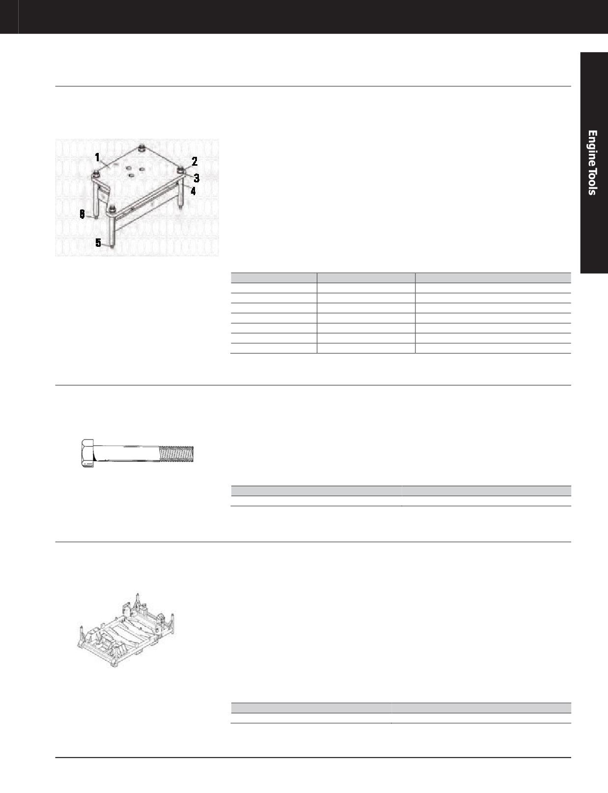
Adapter Group
Model Usage: MY2000 C-15 and C-16 Engines
• Used to mount MY2000 C-15 and C-16
3.
Install studs into two 3/4 inch threaded
and 3406E Engines
“Weight-Reduced” engines onto 1U-5750
holes midway down cylinder block.
Engine Repair Stand
Warranty: Caterpillar ®Six Months
4.
Screw studs in as far as possible (some may
• Allows 360 degree rotation of engine
bottom-out before stud shoulder contacts
cylinder block).
• Attachment location minimizes number of
componentsthatmustberemoved
5.
Install 180-2875 Spacer Assembly (not
serviced), 180-2876 Plate (not serviced), and
• Also fits 3406E Engines at the same
5P-8248 Hard Washers.
attachment location
6.
Securely tighten 2J-3506 Full Nuts.
Application Procedure
7.
Attach 180-2876 Plate (not serviced) to head
1.
Remove filter assembly from inlet manifold
of 1U-5750 Engine Repair Stand.
side of engine.
2.
Install studs into two 3/4 inch threaded
holes below head gasket joint.
Item
Part Number
Description
—
180-2877
AdapterGroup
1
180-2876
Plate (Not serviced)
2
2J-3506
Nut
3
5P-8248
Hard Washer
4
180-2875
Spacer Assembly (Not serviced)
5
205-9315
Special Stud (long)
6
205-9314
Special Stud (short)
Bolt
Model Usage: 3046 Diesel Engine
• Used to fasten 3046 Engine to engine stand
• Size:M10 x 1.25 x 90 mm (3.5 in)
for disassembly and assembly (4 bolts
Warranty: Caterpillar ®Six Months
• Metric bolt class (grade): 10.9
required)
Reference
• Used with 1U-9352 Engine Stand
• SENR6458, Special Instruction, Disassembly
• Provides a source for this special hard-to-find
and Assembly of 3046 Engines
bolt (most common fine-threaded bolts are not
long enough)
Part Number
Description
9U-7847
Bolt
Adjustable Engine Stand
Essential Tool
• Used to support C175-16, C175-20, and
• Stand segments unbolt and expand to fit
797 Off-Highway Truck retro-fit engines for
larger C175-20 engine
Model Usage: C175 Engine
storage, shipping, and reconditioning
• Stackable design allows empty stands to be
Warranty: Caterpillar ®Six Months
• Used with 323-1146 Lifting Group - attaches
stored in less space
to engine stand mounting brackets (for lifting
Specifications
and moving stand with engine installed)
• Length (closed): 3831 mm (150.8 in)
• Has built-in lift truck pockets for moving
empty stand only (not to be used to move
• Width: 2299 mm (90.5 in)
stand while engine is installed)
• Height: 1073 mm (42.2 in)
• Steel wheels on one end of stand allows
• Weight: 2196 kg (4842.0 lb)
engines to be loaded/unloaded from shipping
containers
Part Number
Description
326-5851
Adjustable Engine Stand
JULY 2018 Engine Tools
3-273
Engine Tools
ENGINE LIFTING AND POSITIONING
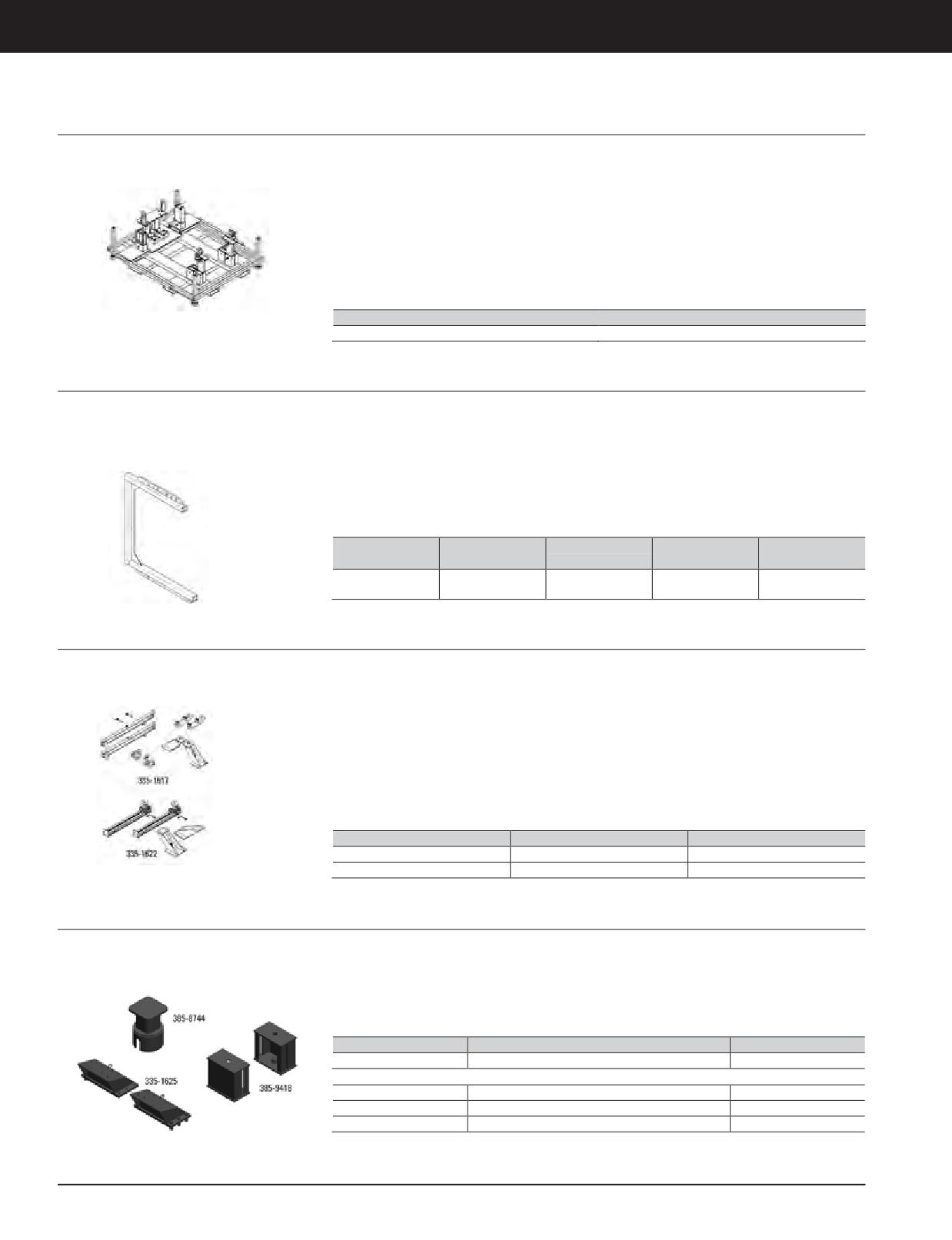
Engine Stand
Model Usage: 3408, 3412, C27 and C32 engines
• Used as a shipping and storage stand for the
Specifications
3408, 3412, C27 and C32 engines
Warranty: Caterpillar ®Six Months
• Dimensions: 2,035 x 1,724 x 593 mm (80.12 x
• Reduces the number of stands required by
67.87 x 23.35 in)
providing one stand that can be used for all of
• Weight: 545 kg (1,201.52 lb)
the following engine platforms: 3408, 3412,
C27 and C32 engines
• Stands are made of steel making them more
durable than their wood counterparts
Part Number
Description
419-7403
Engine Stand
Lifting Bracket
Essential Tool
European Union compliant, CE marked
• Bottom rail has three lifting points for various
engines
Model Usage: Skid Steer Loaders
• Used to remove and install 3034, 3024C, and
3044C Engines
Warranty: Caterpillar ®Six Months
Reference
• Used with an overhead lifting device
• NEHS1113, Tool Operating Manual
• Top rail of bracket has multiple lifting points
for center-of-gravity adjustments
Working Load
Part Number
Description
Overall Size
Weight
Limit
79 x 112 cm
368-0005
Lifting Bracket
340 kg (750lb)
24 kg (53 lb)
(31 x 44 in)
Rail System, 795F AC Engine
Model Usage: 795F AC
European Union compliant, CE marked
• Due to overhead obstruction, rails allow
engine to be rolled forward and backward for
Warranty: Caterpillar ®Six Months
• Used to support the C175 engine during
removal and installation
removal and installation in the 795F AC Off-
Highway Truck
Reference
• Includes rear and front rail tool groups and
• NEHS1096, Tool Operating Manual
various support brackets
• KENR8726, 795F AC Off-Highway Engine
• Rear rail tool group can be used independently
Supplement
without using the front rail tool group
Part Number
Description
Weight
335-1617
Rear Rail Group
42 kg (92 lb)
335-1622
Front Rail Group
158 kg (349lb)
R&I Rail Tool Group, 793F AC Engine
Model Usage: 793F AC
• Used to support the C175 engine during
• Used with Front Rails that are part of the
removal and installation
335-1622 Front Rail Group
Warranty: Caterpillar ®Six Months
• Allows removal/installation of engine without
Reference
removing electrical cabinet off the machine
• NEHS1096, Tool Operating Manual
Part Number
Description
Weight
394-0867
793F AC Engine R&I Rail Tool Group
-
Specifications
335-1625
Mounting Bracket Group
98 kg (216.1lb)
385-8744
Lift Cap Assembly
10 kg (22.0 lb)
385-9418
793F AC Front Rail Tool Group
41 kg (90.4 lb)
3-274 JULY 2018 Engine Tools
Engine Tools
ENGINE LIFTING AND POSITIONING
Motor Grader Rear Engine Support Groups
Model Usage: All G-Series Motor Grader Engines
• Used to service all G-Series Motor Grader
• Contain 2 support assemblies which bolt to
engines
both sides of flywheel housing to support
Warranty: Caterpillar ®Six Months
engine; forcing bolt and locknut properly
• Allow removal of motor grader transmission
position support assembly, which is attached
without removing engine
to rear of engine, against top surface of motor
• Saves about 4 hours of labor
grader frame
• Motor grader model serial number listed in
chart coincides with release of load sensing
hydraulic systems, threaded gland hydraulic
cylinders, and corporate electrical systems
Model
Serial Number
Tool Group
61M-12027 & Up
A
12G
3WC1067&Up
A
96U-7046 & Up
D
14G
3L193 & Up
D
16G
93U-2679 & Up
E
87V-8360 & Up
C
11W-1251 & Up
C
120G
61W591 & Up
C
2AB62 & Up
C
74V-2321 & Up
B
130B
12W-1082 & Up
B
59K82 & Up
B
72V-10334 & Up
A
140G
13W741 & Up
A
50H-1261 & Up
A
160G
4JD141 & Up
A
Part Number
Description
Qty.
Engine Support Group A a
0S-1595
Bolt
8
1D-5118
Jam Nut
2
4B-4280
Washer
8
4N-7862
Support Assembly, Right
1
8H-6508
Forcing Bolt
2
Engine Support Group B c
1D-5118
Jam Nut
2
7B-3235
Bolt (English)
4
8H-6508
Forcing Bolt
2
Engine Support Group C a
0S-1595
Bolt
8
1D-5118
Jam Nut
2
8H-6508
Forcing Bolt
2
Engine Support Group D
(Use 3 washers between support assembly and flywheel housing at each 7K-4370 bolt)
1D-5118
Jam Nut
2
2P-8913
Support Assembly
2
4B-5275
Washer
12
7K-4370
Bolt
4
8H-6508
Forcing Bolt
2
Engine Support Group E
(Use shims as required between support assembly and flywheel housing at both support locations)
1D-5119
Jam Nut
2
4B-6208
Forcing Bolt
8
4N-6063
Shim
12
4N-7358
Support Assembly
2
8S-9092
Bolt
4
a. Includes: Support Assembly, Left, Qty. 1
b. Includes: Support Assembly, Qty. 2
c. Included: Support Assembly, Qty. 2
JULY 2018 Engine Tools
3-275
Engine Tools
C175 ENGINE TOOLS
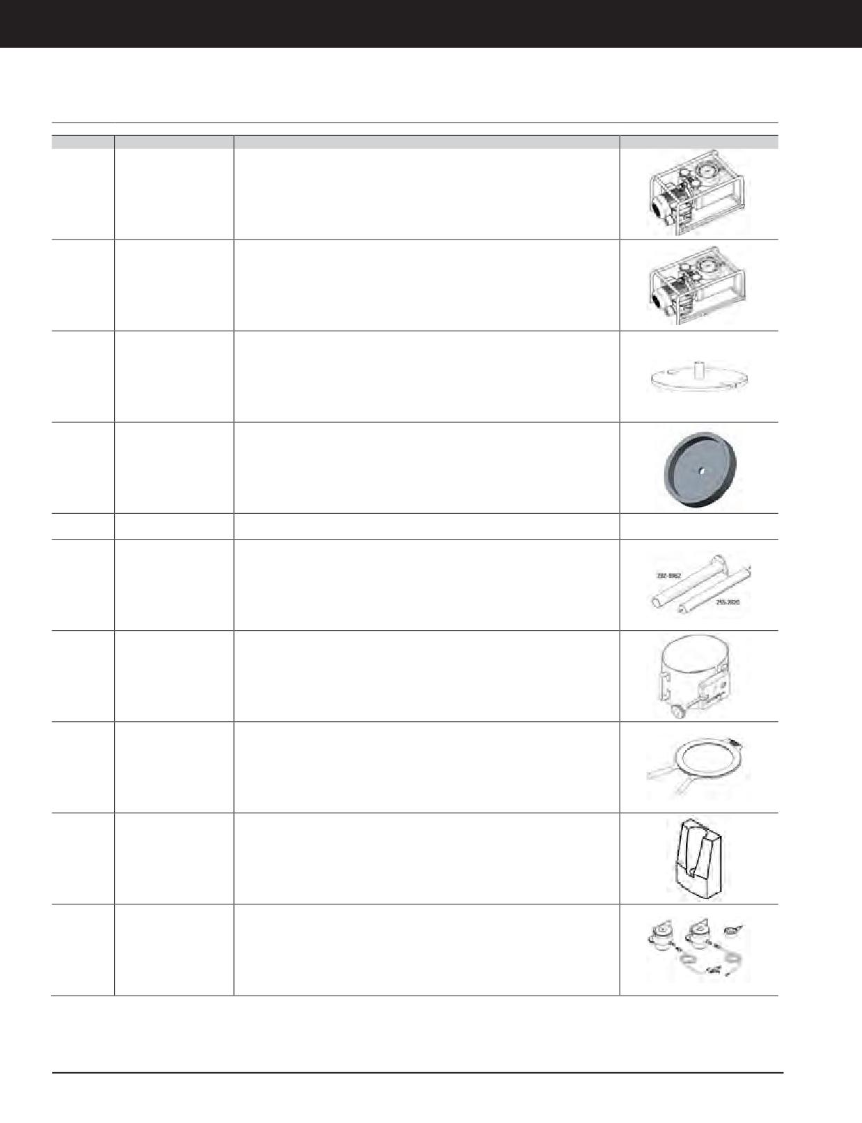
C175 Engine Repair Tools
Part No.
Part Name
Description
Image
227-6724
Hydraulic pump
Electric 120V AC and 60Hz - used to operate 253-3272 cylinder group.
227-8834
Hydraulic pump
Electric 240V AC and 50Hz - used to operate 253-3272 cylinder group
250-4586
Crank seallocator
Used to install crankshaft seals
250-4587
Crank seal installer
Used to install crankshaft seals
Seal kit for stud
253-3275
Used to repair 253-3272 hydraulic cylinder group
tensioner cylinder
255-2820
Camshaft pilot
Used to pilot camshaft during removal and installation
255-8897
Piston ring compressor
Used to compress piston rings for installation into cylinder bore
271-0504
Piston ring expander
Removes and installs piston rings
Used to aid connecting rod installation - requires one 339-6503 bolt to secure
274-5875
Connecting rod guide
guide onto connecting rod
Used to tension main bearing studs. Includes 178-9312 hose, 185-0683 gauge, 253-
Main bearing stud
278-1150
3272 cylinder group and 253-3276 coupler. 253-3272 requires appropriate pump to
tension group
be chosen from NEHS0944 TOM
3-276 JULY 2018 Engine Tools
3-276
Engine Tools
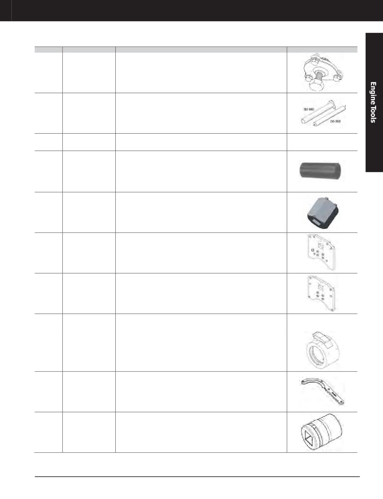
C175 ENGINE TOOLS
Part No.
Part Name
Description
Image
279-3473
Turning tool
Usedtomanually rotate engine crankshaft
282-9962
Camshaft guide
Used to install and remove camshaft
For use with 295-5490 fuel system filter cart group. Replaces the flow limiter in
283-2281
Flushinglimiter
the cylinder 2 location to enable the best flow through the rail supporter while
flushing
284-1503
Valve guide collar
Used for insertion of valve guides. It requires 283-0052 valve guide driver.
284-5266
Spanner wrench
Used to remove and install the main bearing cap studs onto the cylinder block
Plate - engine stand
Bolts to front of engine block and requires 4C9832 roll over stand and New C175
284-8766
adapter (front)
Roll Over Stand (Available to order by end of May-2016)
Plate - engine stand
Bolts to rear of engine block and requires 4C9832 roll over stand and New C175
284-8777
adapter (rear)
Roll Over Stand (Available to order by end of May-2016)
288-9169
Adapter
Used with 2P-8260 to press cylinder liner into cylinder bore
Used with cylinder pack puller to remove cylinder pack (Not required if engine is
288-9171
Bridge
rotated to push cylinderliner and connecting rod up andout of engine block)
304-9575
Bellows installation tool
Used to align bellows on exhaust side of turbochargers
304-9576
Bellows checking tool
Used to check alignment of bellows on exhaust side of turbochargers
12 pt M24 3/4 drive
312-2840
Used to torque M24 bolts on heads and flywheel
impact socket
JULY 2018 Engine Tools
3-277
Engine Tools
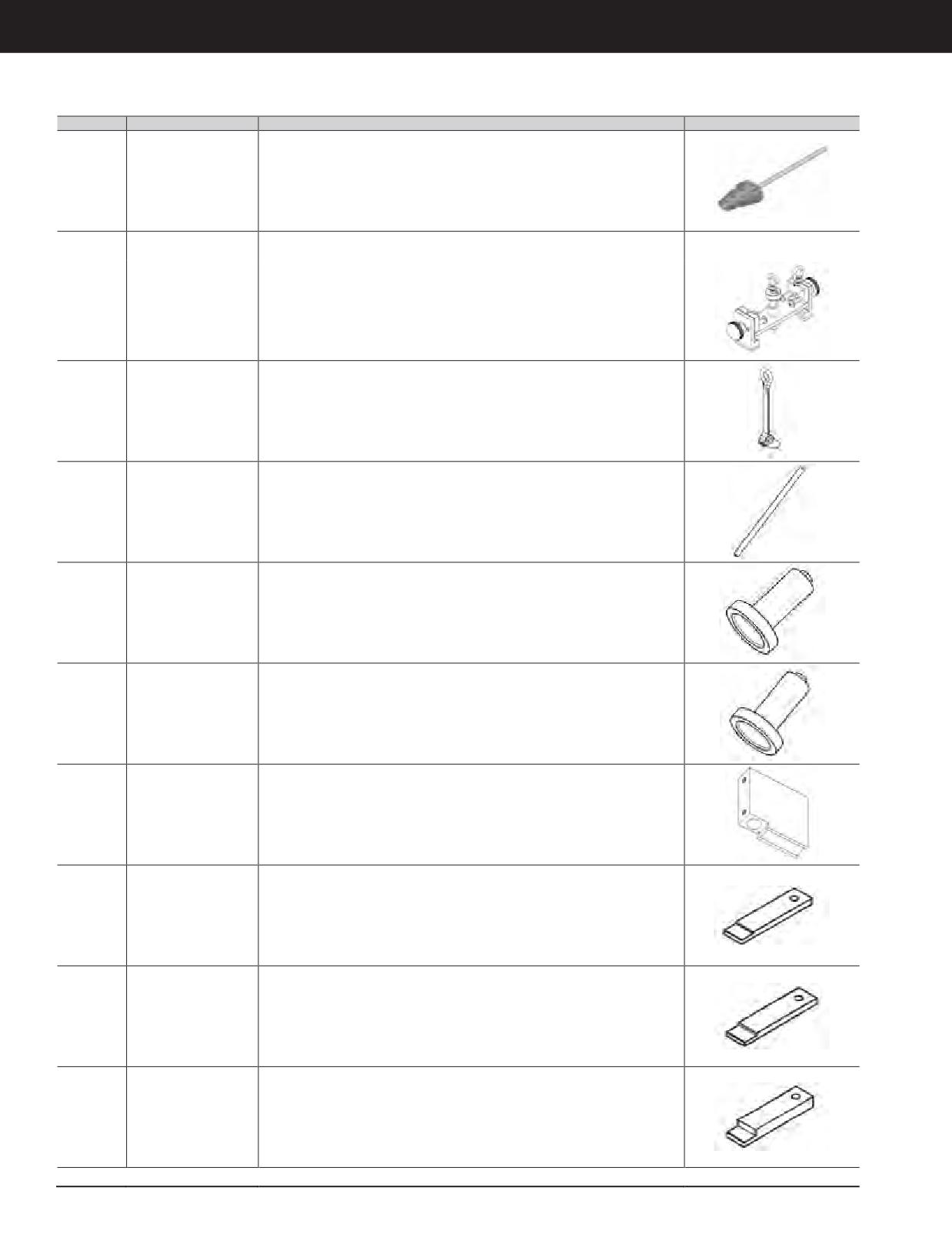
C175 ENGINE TOOLS
Part No.
Part Name
Description
Image
312-3204
Injector bore brush
Used to clean fuel injector bore
Bolt
322-2078
Used to install crankshaft seals
(M24 x 2 x 63.5)"
Used to install cylinder pack cylinder liner, piston and connecting rod) into the
322-3564
Cylinder pack installer
block
323-1146
Enginelifting device
Engine lifting device (set of two pieces)
"Guide bolt
323-4712
Used to locate flywheel during installation
(M24 x 2 x 500)"
Valve recession gauge
326-7689
block
Used to set 148-2997 tool to zero for inlet valve measurements
(inlet valve)
Valve recession gauge
326-7693
Used to set 148-2997 tool to zero for exhaust valve measurements
block (exhaust valve)
Valve recession base
Usedto determine actualvalve and valveseat wear.Adapts 148-2997valve
326-7698
assembly
recession tool for use with C175 engines.
327-8644
Piston ring gauge
Used to check top ring groove to determine piston reusability
327-8645
Piston ring gauge
Used to check second ring groove wear
327-8646
Piston ring gauge
Used to check bottom (oil ring) groove to determine piston reusability
3-278 JULY 2018 Engine Tools
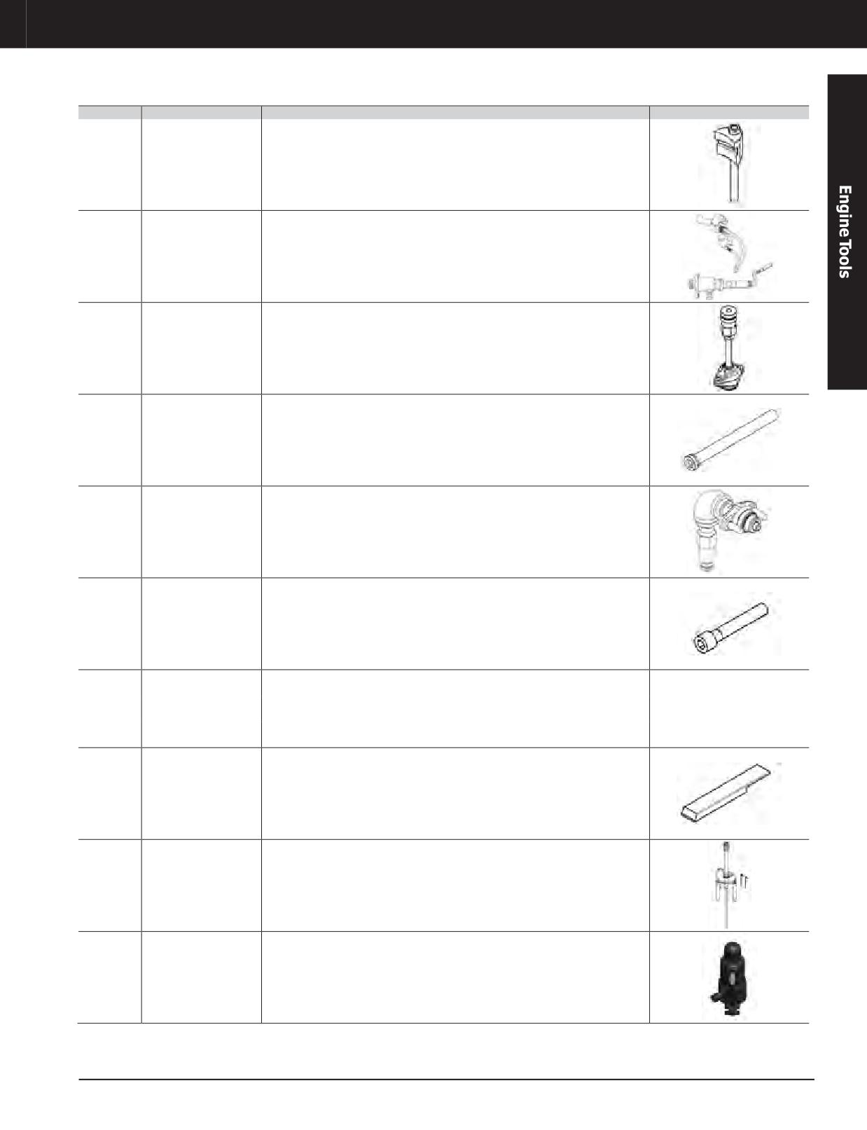
Engine Tools
C175 ENGINE TOOLS
Part No.
Part Name
Description
Image
Piston liner spacer
Used to support the cylinder pack when removing or attaching the cylinder pack
328-5926
assembly
installation tool Assembly consists of 2 bolts and two spacers
329-3831
Air powered turning tool
Used to rotate crankshaft with air powered motor
330-7185
Fuel supply connection
Supply connection for use with 295-5490 fuel system filter cart group
Electronic unit injector
333-0759
Used to install and remove electronic unit injectors
sleeve remover/installer
334-4442
Fuel return connection
Return connection for use with 295-5490 fuel system filter cart group.
Bolt
339-6503
Usedto secure 274-5875guide toconnecting rod
(M13 x 1.25 x 82)
Used to cap openings in the fuel system to prevent system contamination when
339-9352
Fuel line cap kit
removinginjectors, quill tubes, or flowlimiters
Used to cap openings in the fuel system to prevent system contamination when
339-9353
Fuel line cap kit
removing high pressure fuel pump
Used to cap openings in the fuel system to prevent system contamination when
339-9354
Fuel line cap kit
removing high pressure fuel rails
369-4007
Main bearing driver
Used to roll main bearing halves in or out.
Used to raise the piston for inspection, removal, or installation of C175 connecting
369-4008
Piston raising tool
rod bearings
Used to remove valve seats on machine cylinder heads hydraulically. Can service
complete head in less than 2 minutes. Services only non-water coled heads art
371-0351
Valve Seat Removal Tool
this time. Requires 445-8987, 445-8988 and 445-8989. (NOTE: This puller will also
removeG3500watercooledinsertswith optional collets. 3500machine andC175
EPG collets available)
JULY 2018 Engine Tools
3-279
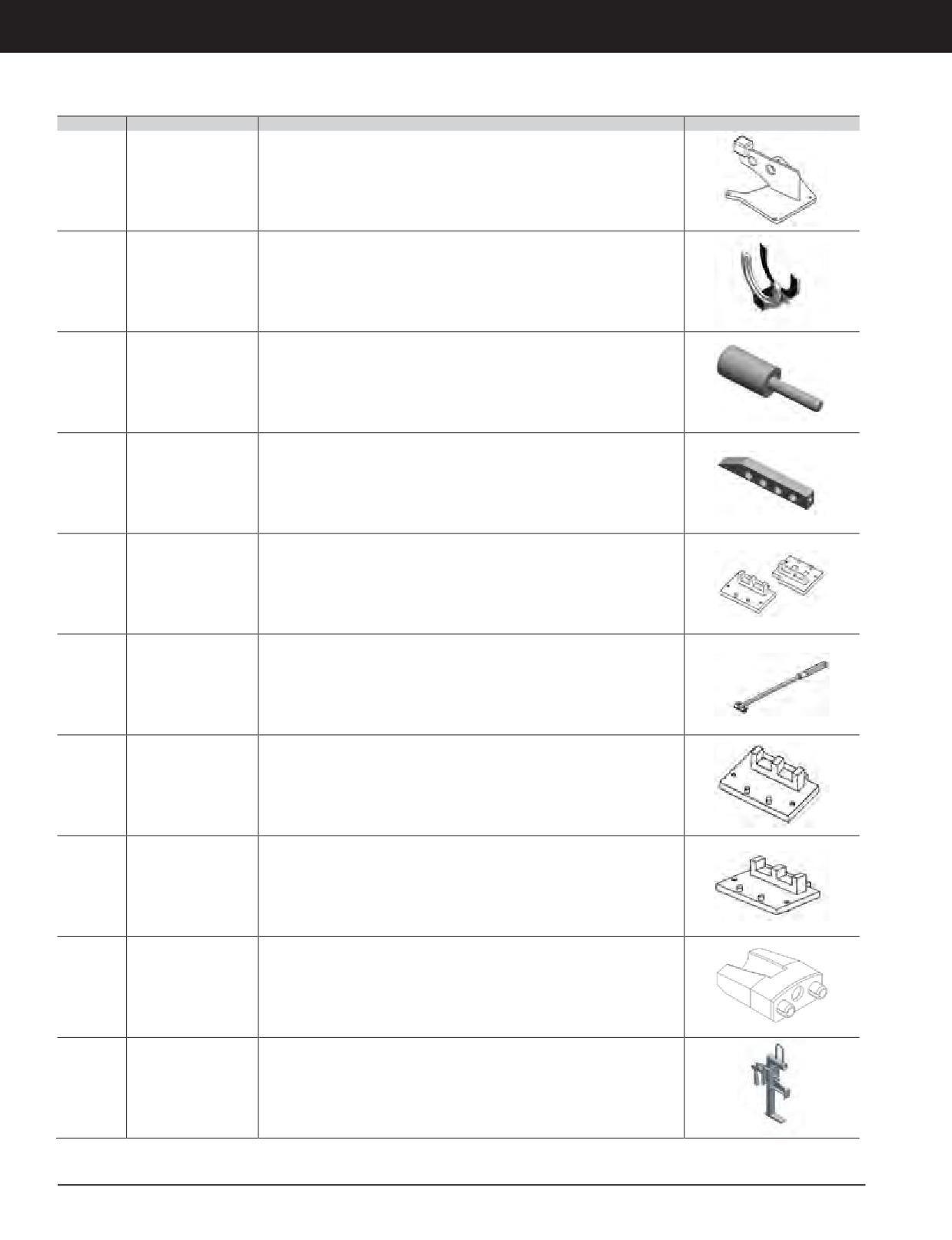
Engine Tools
C175 ENGINE TOOLS
Part No.
Part Name
Description
Image
Cylinder Head Lifting
371-1079
Cylinder Head Lifting Device - Bolt on Type
Device
396-9127
Bellows compressor
Used to service 291-5165 and 437-3038 bellows in all C175 engines
Used to assist in installation of piston wrist pin in piston and rod assembly in
415-1205
Piston Wrist Pin Guide
C175-16 andC175-20 Engines. Reducestime by providingleadinalignment for the
pin into the piston crown and rod eye bore.
Nylon guides are used to assist in the installation of crankshaft into main journals.
Crankshaft Installation
417-2349
The nylon guides fit over front and rear main cap studs reducing possibility of
Guides
component damage due to crankshaft contact with studs.
C175 Cam Lifter
417-2869
Provide the cam lift group to support the C175 tools
Assembly Supports
Crankshaft turning tool for C175 CRC tools. Used to rotate the crankshaft when
417-3193
Crankshaft Turning Tool
checking the crankshaft end clearance on initial fit up.
C175 Cam Lifter
417-9607
Provide the cam lift group to support the C175 tools
Assembly Supports
C175 Cam Lifter
417-9617
Provide the cam lift group to support the C175 tools
Assembly Supports
Connecting rod guide
Used to aid connecting rod installation - requires one 339-6503 bolt to secure
418-1340
for type 2 connecting
guide onto connecting rod
rods
C175 Damper Lifting
Lift assembly which permits the secure removal and installation of crankshaft
419-9827
Device
damper with overhead crane
3-280 JULY 2018 Engine Tools
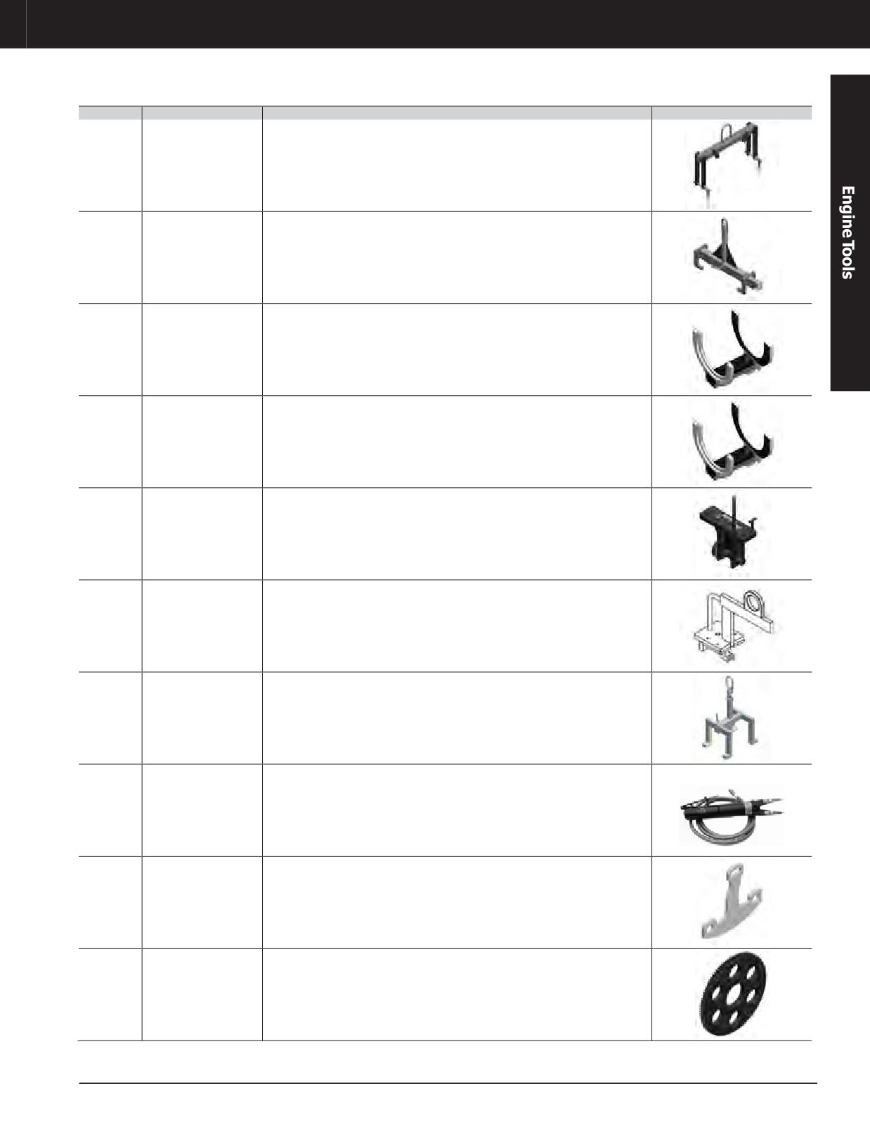
Engine Tools
C175 ENGINE TOOLS
Part No.
Part Name
Description
Image
Tool used to securely remove and install the main bearing caps when the block
Main bearing caplifting
420-7630
isin the engine roll over stand. The two pinsin the storage holes go through the
device
lower frame holes and main bearing cap lifting eyes.
Cylinder Block Lifting
Provide the tool assembly used to lift the Cylinder Blocks.This one piece tool fits
420-9053
Tool
in the block V and is positioned under two inlet manifold ports.
421-4079
Bellows compressor
Used to service 389-9659 and 363-2086 bellows in all C175 engines
421-4080
Bellows compressor
Used to service 348-9252 bellows in all C175 engines
Removes and installs camshaft bearings utilizing features on the top of the block
Cam bearing installation
423-1236
to align the cam bearing bore to correct centerline to remove and install the
removal tool
camshaftbearings andeliminating the needformultisection tooling.
Cylinder Head Lifting
Used to lift the head in the horizontal position and requires no hardware for C175-
423-1743
Device
16&C175-20.
Crankshaft Lifting
• Provides a safe way to lift C175 16- and 20-cylinder crankshafts
424-8895
device
• Lifts by the counterweights eliminating possible damage to journal surfaces
C175 piston Assembly
430-4389
C175 piston assembly snap ring compressor
Snap Ring Compressor
Air System Lifting
432-5403
C175-20 HAA Air System Lifting device
device
434-3321
Flywheel adapter
Flywheel adapter used to connect C175- 20 machine engines to dynomometer
JULY 2018 Engine Tools
3-281
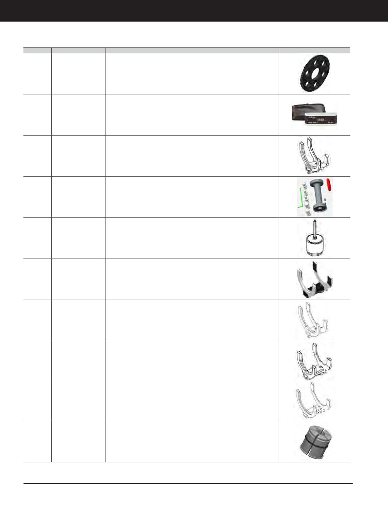
Engine Tools
C175 ENGINE TOOLS
Part No.
Part Name
Description
Image
434-3331
Flywheel adapter
Flywheel adapter used to connect C175- 16 machine engines to dynomometer
Turbocharger digital
Digital protractor used to measure accurate orientation of turbos and end
437-5632
alignment gage
housings
440-0210
Bellows compressor
Used to service 315-7909 bellows in all C175 engines
Serves as an universal tool group for C175, 3500, 3400 and C27-32 engine series
• Used to position ferrules into the bore
Water Ferrule
441-3674
• Improves quality of repair by ensuring that ferrule is installed
Installation Tool Group
perpendicular to the engine block
• Reduces installation time with less potential for leaks
442-5798
Cylinder pack puller
Used to pull liner, piston and connecting rod, as an assembly, from engines
443-7540
Bellows compressor
Used to service 354-3510 bellows in HAA 793F and 795F Turbine Outlet
443-7542
Bellows compressor
Used to service 258-8016 bellows in HAA 797F Front Turbine Outlet
Used to service 344-0079 bellows in HAA 797F Exhaust Bypass and Rear Turbine
443-7543
Bellows compressor
Inlet
443-7544
Bellows compressor
Used to service 365-6532 bellows in HAA 797F Rear Turbine Outlet
Collet As. for C175
Collet assembly to support C175 standard valve seat extraction. Used with 371-
445-8987
Standard Exhaust Valve
0351 Extraction Cylinder Gp
Seat
3-282 JULY 2018 Engine Tools
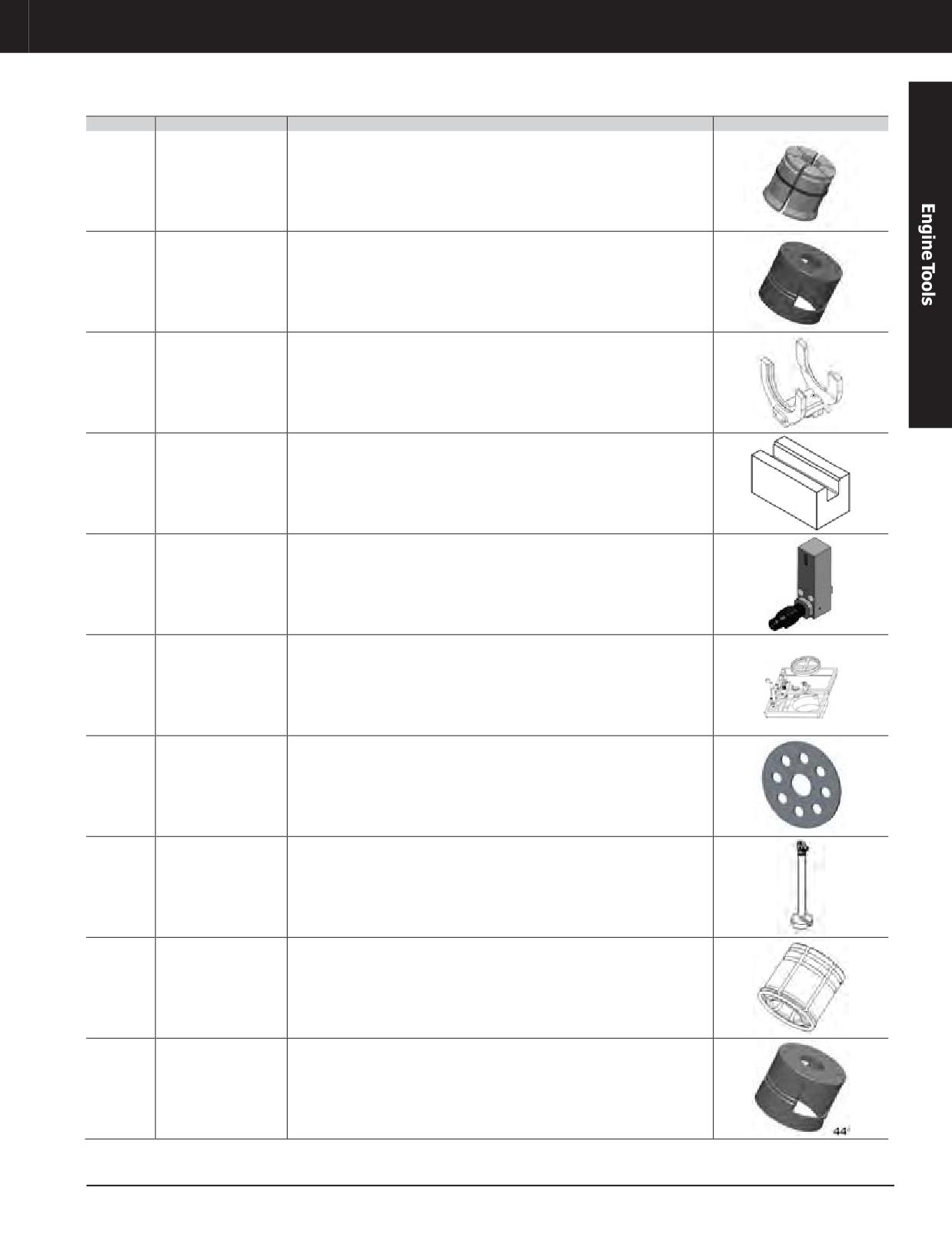
Engine Tools
C175 ENGINE TOOLS
Part No.
Part Name
Description
Image
Collet As. for C175
Collet assembly to support C175 standard valve seat extraction. Used with 371-
445-8988
Standard Intake Valve
0351 Extraction Cylinder Gp
Seat
Standoff for Standard
Collet assembly to support C175 standard valve seat extraction. Used with 371-
445-8989
Valve Seat
0351 Extraction Cylinder Gp
452-6804
Bellows compressor
Used to service 443-5940 bellows in LAA 793F, 795F and 797F outboard turbine inlet
Used to determine reuse and wear of the vibration dampening material (FKM) on
455-8106
Rod Bolt Reuse Gage
the new 428-7386 rod bolts.
Cycle counter kit for
Cycle counter kit for 253-3272 hydraulic cylinder group. It provides a way to track
457-3255
stud tensioner cylinder
cylinder use and replace change bushing at recommended 2000 cycle interval.
Valve spring
New group replaces original 333-0758. It does not require removal of fuel injector
459-4664
compressorandtiming
and wiring harness. It is more robust and designed for high volume applications.
wheel group
Includes 459-4666 timingindicator group used to set engine to top dead center
467-5334
Flywheel Adapter
Used to connect C175 - EPG Machine Engine to Dyno
Lifting As. (C175 Front
469-7628
Provide lifting assembly used to lift C175 front gear train cluster gear
Gear Cluster Group)
Collet assembly to support C175 standard valve seat extraction. Used with 371-
472-0580
Collet
0351 Extraction Cylinder Gp
472-0581
Standoff
"Used with 472-0480 collet
JULY 2018 Engine Tools
3-283
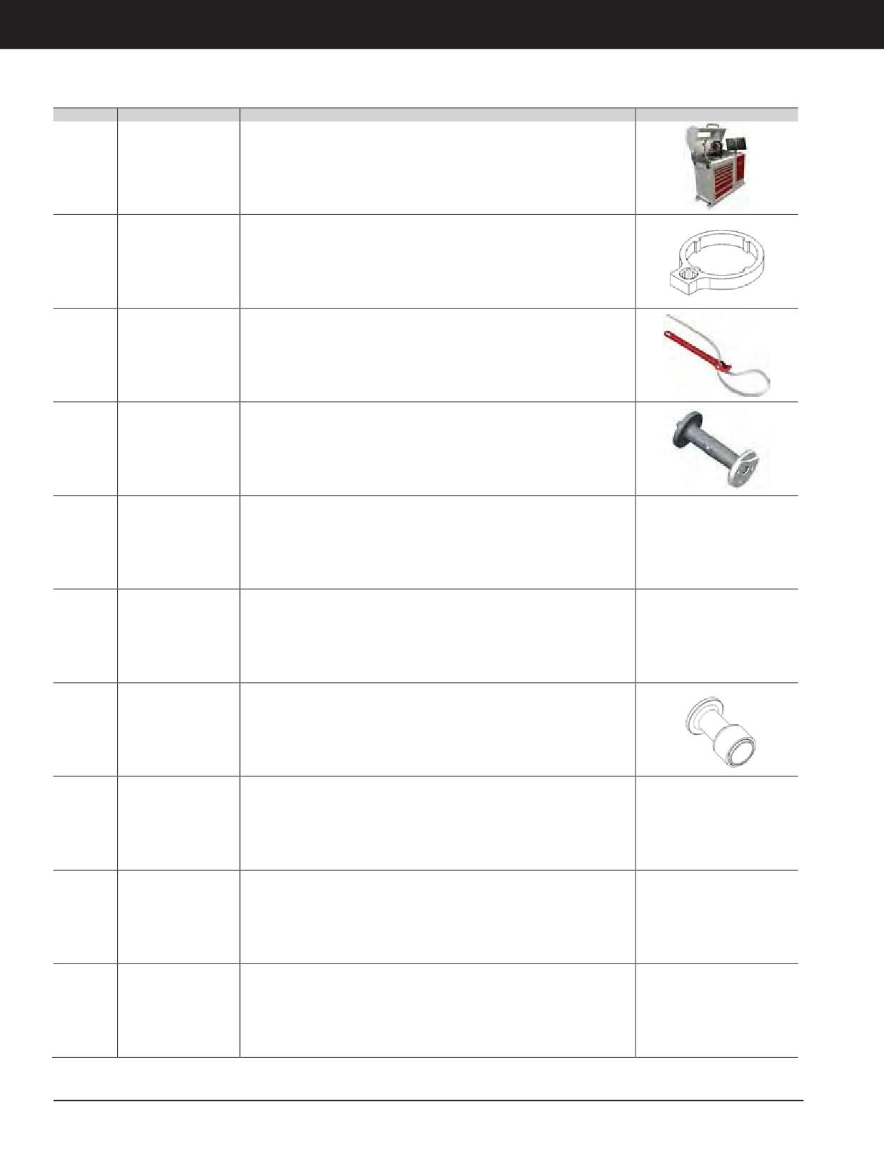
Engine Tools
C175 ENGINE TOOLS
Part No.
Part Name
Description
Image
Turbo Charger Balancer
473-7085
(C4.4-C175)
Balancer for balancing turbochargers when replacing any component and
473-7087
Turbo Charger Balancer
especially after bearing and seal replacement
(ABB)
(C175-3600ABB)
476-2902
Spanner Nut Wrench
Spanner wrench for larger bearing locknut on 381-7341 water pump
Provide support for the C175-20 Tier 4F Engine in changing the secondary fuel
477-3946
Fuel filter strap wrench
filter
Doweldriversfor 6V-3535dowel(block top and bottomofhead) andcamshaft
478-1932
Dowel driver
segment
• Provides safe and stable pry point when performing crankshaft lift measurement
Crankshaft lift test
to determine proper bearing installation
478-1933
fixture Assembly
• Eliminates damage from incorrect leverage location
• Bolts to existing holes and is used when block is inverted
PTO shaft stop tool
Tool assembly used to hold 373-7691 housing assembly PTO shaft while tightening
478-1934
assembly
rear gear train PTO gear bolts
Provide driver assembly used to install 109-5722 lip seal in C175 engines and also
482-7518
Seal Installer
prevents misalignment used in CRC's
Valve Lash Feeler
482-7519
C175 Valve Lash Feeler Gauge
Gauge
PTO Wear Sleeve
482-8221
Driver assembly used to install 9X-7726 wear sleeve
Installation Driver
Piston Cooling Jet
• Used to check proper piston cooling jet alignment
483-8572
AlignmentTool
• Prevents engine overheating due to misaligned coolingjet nozzles
3-284 JULY 2018 Engine Tools
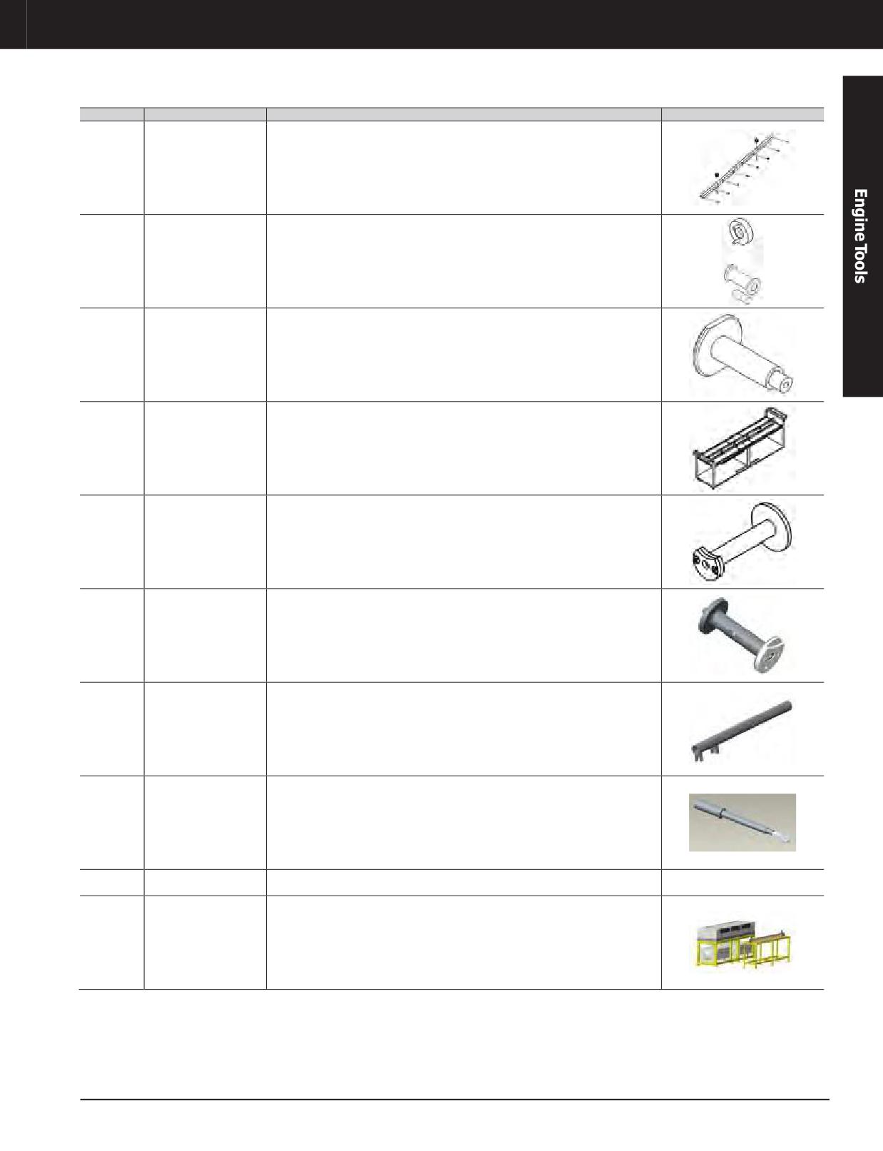
Engine Tools
C175 ENGINE TOOLS
Part No.
Part Name
Description
Image
Tool As.- Alignment
484-0506
Intake manifold subassembly alignment tool and lifting device
(Intake Manifold)
484-7869
Wear Sleeve
Driver assembly used to Install A/C compressor pulley wear sleeve
485-9771
Wear Sleeve Driver
Driver assembly used to install alternator pulley wear sleeve
Doweldriversfor 6V-3535dowel(block top and bottomofhead) andcamshaft
484-9036
Dowel driver
segment
Tool As.-Cart
To provide tool assembly-alignment used to align intake manifold and lifts onto
485-3789
(Intake Manifold)
engine for installation or removal
Driver As. (C175 Top
488-1752
Provide Driver Assembly for 384-3712 dowel (top center block)
Center Block)
488-2468
Dowel Driver
To install new 493-5366 oil supply dowel
Turbocharger Oil line
491-3246
To install and align turbocharger oil lines
alignment tool
Tool As.-Wrench
491-3256
Preset Torque wrench and head for 388-8842 camshaft segment bolts
(Torque - C175 CAM)
Engine Dynamometer
Provide tank assembly used to displace water left in the cooling systems of the
498-6326
Coolant Flushing System
engine after dyno testing with open circuit cooling systems
Flushing system and assembly fixture for Reuse and Salvage of 415-3234 and 415-
Fuel Rail Assembly and
502-0889
3235C175CommonRail Assemblies. Includes adapters and alignmenttooling as
Flushing System
well as table and fixtutes
JULY 2018 Engine Tools
3-285
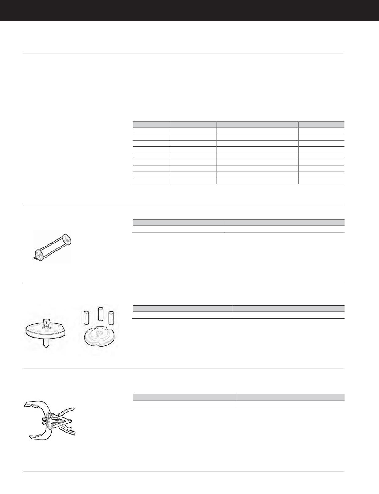
Engine Tools
C8.7 ENGINE TOOLS
C3.3B Engine Tooling
Model Usage: 308E, 906H, 907H, 908H
• 390-1134 - Glow plug adapter used to check
• 390-1146— Used to easily replace
compression using the 9U-6274 Compression
crankshaft sleeve
Warranty: Caterpillar ®Six Months
Test Kit
• 390-1149 - Used to easily replace camshaft
• 390-1135 - Replaces idle gear bushing
cover
• 390-1136— Usedto replace valve guides
• 390-1150— Used to easily pull injection
pump gear (use with 154-6360)
• 390-1140— Replaces front cover oil seal
• 390-1151 - Used to connect governor rod
• 390-1142 - Used to replace valve bridge
Part No.
Description
Dimensions
Weight
390-1134
Plug Adapter
200 x 16 mm (7.9 x 0.6in)
0.1 kg (0.2 lb)
390-1135
Bush
152x 44 mm (6.00 x 1.7in)
1.7 kg (3.7 lb)
390-1136
ToolGroup
225 x 19 mm (8.9 x 0.7in)
0.3 kg (0.8 lb)
390-1140
Driver
120 x 95 mm (4.7 x 3.7in)
0.9 kg (2.1 lb)
390-1142
Spacer
60 x 32 x 19 mm (2.4 x 1.26 x 0.7 in)
0.2 kg (0.3 lb)
390-1146
Tool Kit
163 x 101 mm (6.4 x 4.0in)
3.0 kg (6.6 lb)
390-1149
Driver
132 x 80 mm (5.2 x 3.1in)
1.1 kg (2.4 lb)
390-1150
Puller
100 x 40 mm (3.9 x 1.6in)
0.2 kg (0.5 lb)
390-1151
Jig Tool
53 x 38 mm (2.1 x 1.5 in)
.2 kg (0.5 lb)
Rocker Arm Timing and Installation Tool
Model Usage: C8.7 L Engine
• Usedto aid inthe assembly of therocker arms
• Five lock blocks are included
Warranty: Manufacturer’s
Part Number
Description
456-7964
Rocker Arm Timing and Installation Tool
Liner Projection Measurement
Model Usage: C8.7 L Engine
• Used to hold the cylinder liner in position for
• 456-7965 and 457-9786 are used together
liner projection measurement
Warranty: Manufacturer’s
Part Number
Description
456-7965, 457-9786
Liner Projection Measurement
Piston Ring Pliers
Model Usage: C8.7 L Engine
• Used to remove and install Piston Rings
Specifications
Warranty: Manufacturer’s
• Weight: 0.5 kg (1 lb)
Part Number
Description
456-7966
Piston Ring Pliers
•
3-286 JULY 2018 Engine Tools
3-286
Engine Tools
C8.7 ENGINE TOOLS
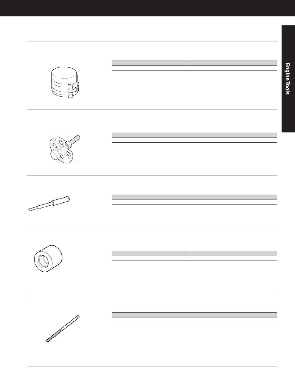
Piston Ring Compressor
Model Usage: C8.7 L Engine
• Compresses the Piston Rings for assembly of
Specifications
the piston into the Cylinder Block
Warranty: Manufacturer’s
• Weight: 0 .5 kg (1 lb)
Part Number
Description
456-7967
Piston Ring Compressor
Valve Spring Compressor
Model Usage: C8.7 L Engine
• Compresses the valve springs for removal of
Specifications
the Valve Spring Locks. Compresses all four
Warranty: Manufacturer’s
• Weight: 1.4 kg (3 lb)
valve springs at the same time.
Part Number
Description
456-7968
Valve Spring Compressor
Valve Guide Driver
Model Usage: C8.7 L Engine
• Removes the Valve Guide from the Cylinder
Specifications
Head
Warranty: Manufacturer’s
• Weight: 0 .5 kg (1 lb)
Part Number
Description
456-7969
Valve Guide Driver
Valve Guide Stop Collar
Model Usage: C8.7 L Engine
• Used to install Valve Guide to the proper
Specifications
depth
Warranty: Manufacturer’s
• Weight: 0 .5 kg (1 lb)
• Used with 456-7969
Part Number
Description
456-7970
Valve Guide Stop Collar
Valve Guide Reamer
Model Usage: C8.7 L Engine
• Used to ream the Valve Guide to the final
Specifications
proper diameter after installation
Warranty: Manufacturer’s
• Weight: 0 .5 kg (1 lb)
Part Number
Description
456-7980
Valve Guide Reamer
JULY 2018 Engine Tools
3-287
Engine Tools
C8.7 ENGINE TOOLS
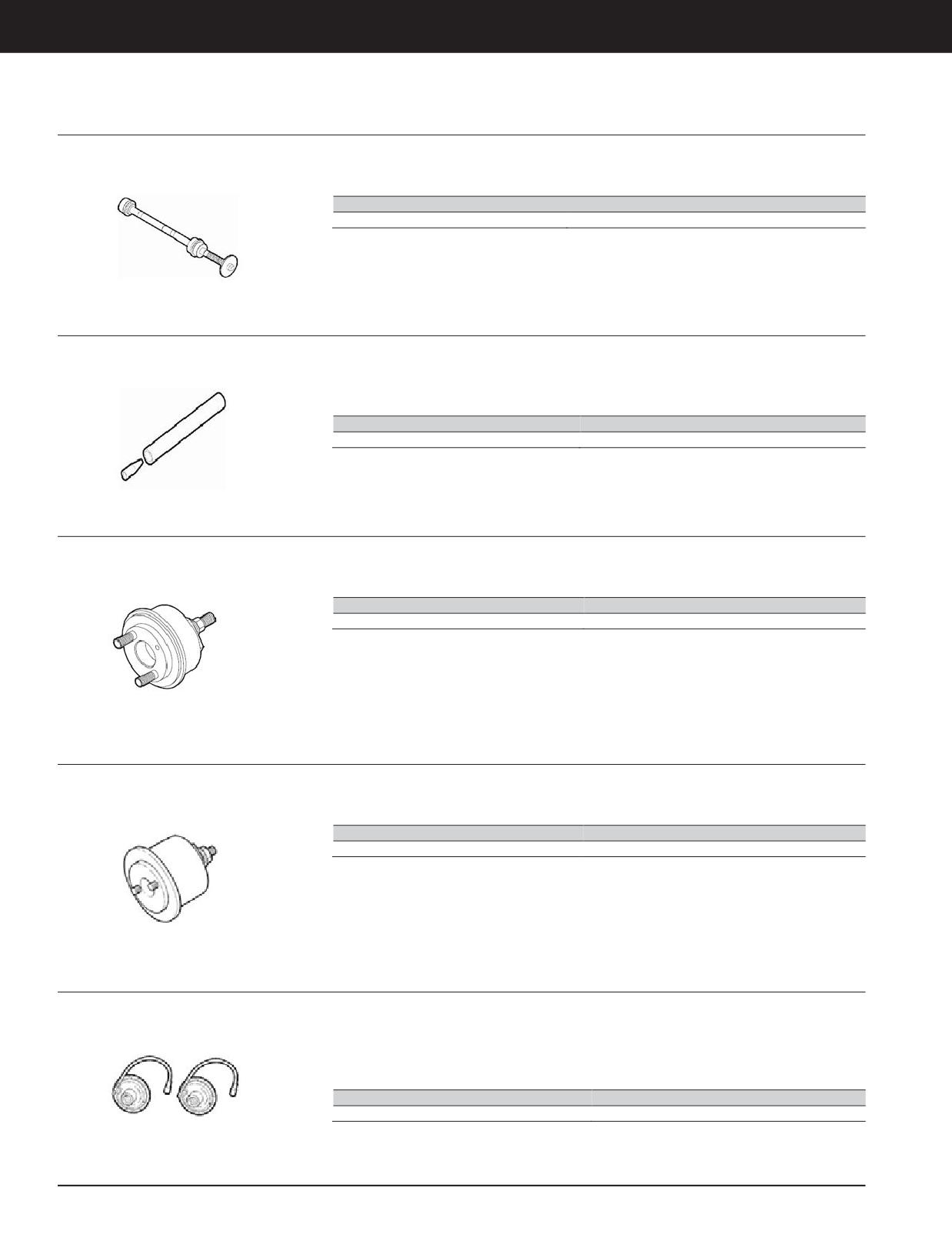
Camshaft Bushing Remove and Install
Model Usage: C8.7 L Engine
• Used to remove and install the Camshaft
Specifications
Bushings
Warranty: Manufacturer’s
• Weight: 8.2 kg (18 lb)
Part Number
Description
456-7982
Camshaft Bushing Remove and Install
Valve Stem Seal Installation
Model Usage: C8.7 L Engine
• Used to install the Valve Stem Seal without
Specifications
damaging the seal
Warranty: Manufacturer’s
• Weight: 0.2 kg (.5 lb)
• Quickly and easily installs the seal by hand
Part Number
Description
456-7983
Valve Stem Seal Installation
Rear Crank Seal Installer
Model Usage: C8.7 L Engine
• Used to install the Rear Crank Seal into the
Specifications
Cylinder Block
Warranty: Manufacturer’s
• Weight: 6.8 kg (15 lb)
Part Number
Description
456-7986
Rear Crank Seal Installer
Front Crank Seal Installer
Model Usage: C8.7 L Engine
• Used to install the front crank seal into the
Specifications
cylinder block
Warranty: Manufacturer’s
• Weight: 6.8 kg (15 lb)
Part Number
Description
456-7987
FrontCrank SealInstaller
Torque Turn Gages
Model Usage: C8.7 L Engine
• A pair of ½ inch and ¾ inch drive Torque Turn
Specifications
Gauges. Used when the special torque-turn
Warranty: Manufacturer’s
• Weight: 1.8 kg (4 lb)
method on bolts is needed.
• More precise than other methods
Part Number
Description
456-7988
Torque Turn Gages
3-288 JULY 2018 Engine Tools
Engine Tools
C8.7 ENGINE TOOLS
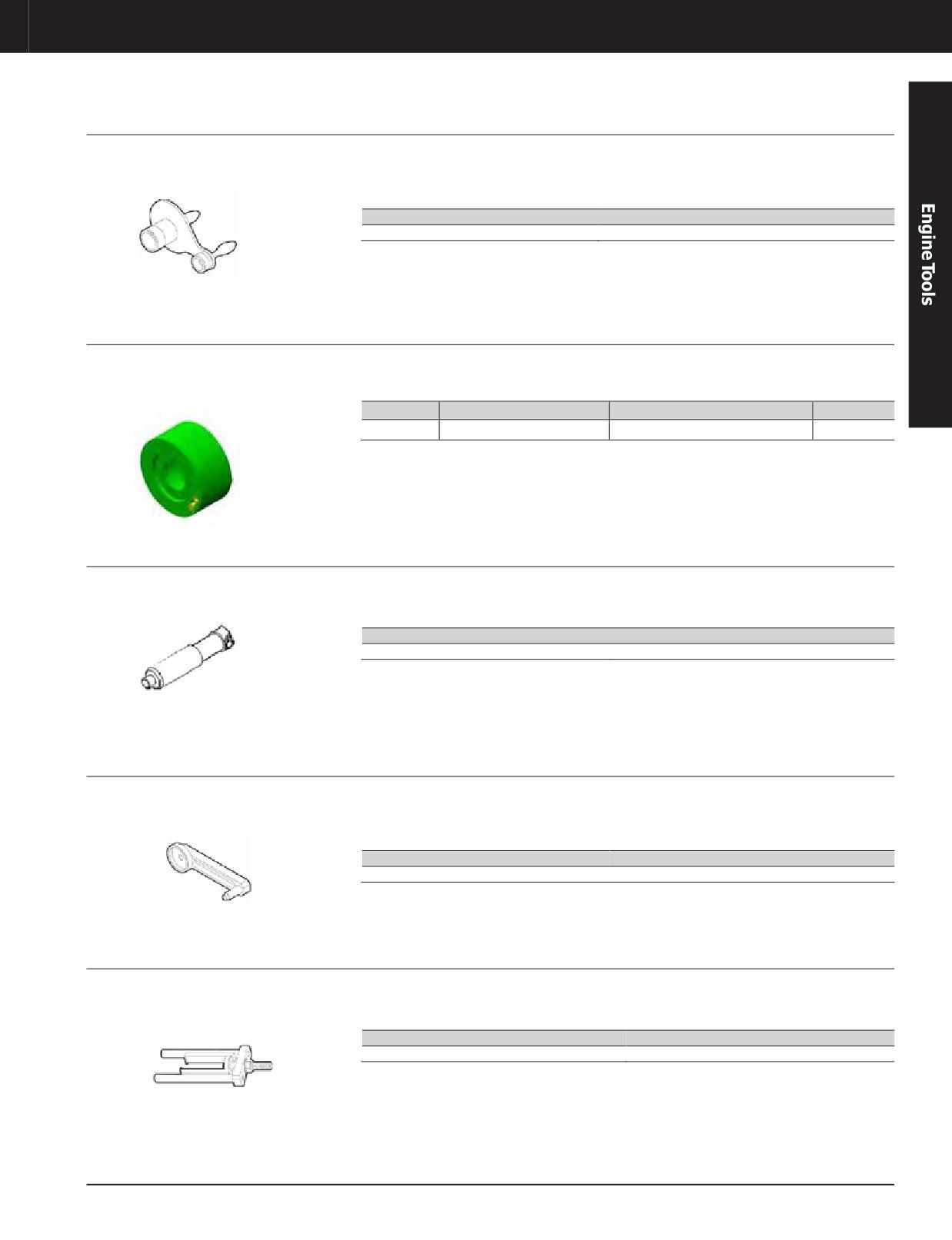
High Pressure Pump Alignment Tool
Model Usage: C8.7 L Engine
• Used for checking and setting the proper
Specifications
distance between the high pressure fuel pump
Warranty: Manufacturer’s
• Weight: 3.1 kg (7 lb)
and the camshaft gear
Part Number
Description
487-3142
High Pressure Pump Alignment Tool
Pump Alignment Tool Assembly
Model Usage: C9.3B
• Alignment tool is used to install the fuel pump
• Used whenever the fuel pump is removed and
on to the C9.3B Engine.
installed onto the engine
Warranty: Caterpillar ®Six Months
Part No.
Description
Dimensions
Weight
533-1183
Pump Alignment Tool Assembly
Dia 70 x 41.6 mm (Dia 3 x 2 in)
1 kg (2.2 lb)
Crankshaft TDC Timing Tool
Model Usage: C8.7 L Engine
• Locks the Crankshaft in No 1 Cyl TDC Position
Specifications
Warranty: Manufacturer’s
• Weight: 0.1 kg (.25 lb)
Part Number
Description
456-7990
Crankshaft TDC Timing Tool
Idler Gear Positioning Gage
Model Usage: C8.7 L Engine
• Determines the correct distance of idler gear
Specifications
between the cam gear and flywheel and sets
Warranty: Manufacturer’s
• Weight: 1.8 kg (4 lb)
correct backlash
Part Number
Description
456-7991
IdlerGear PositioningGage
Injector Puller
Model Usage: C8.7 L Engine
• Used for removing the fuel injectors
Specifications
Warranty: Manufacturer’s
• Weight: 1.1 kg (2.5 lb)
Part Number
Description
456-7992
Injector Puller
JULY 2018 Engine Tools
3-289
C8.7 ENGINE TOOLS
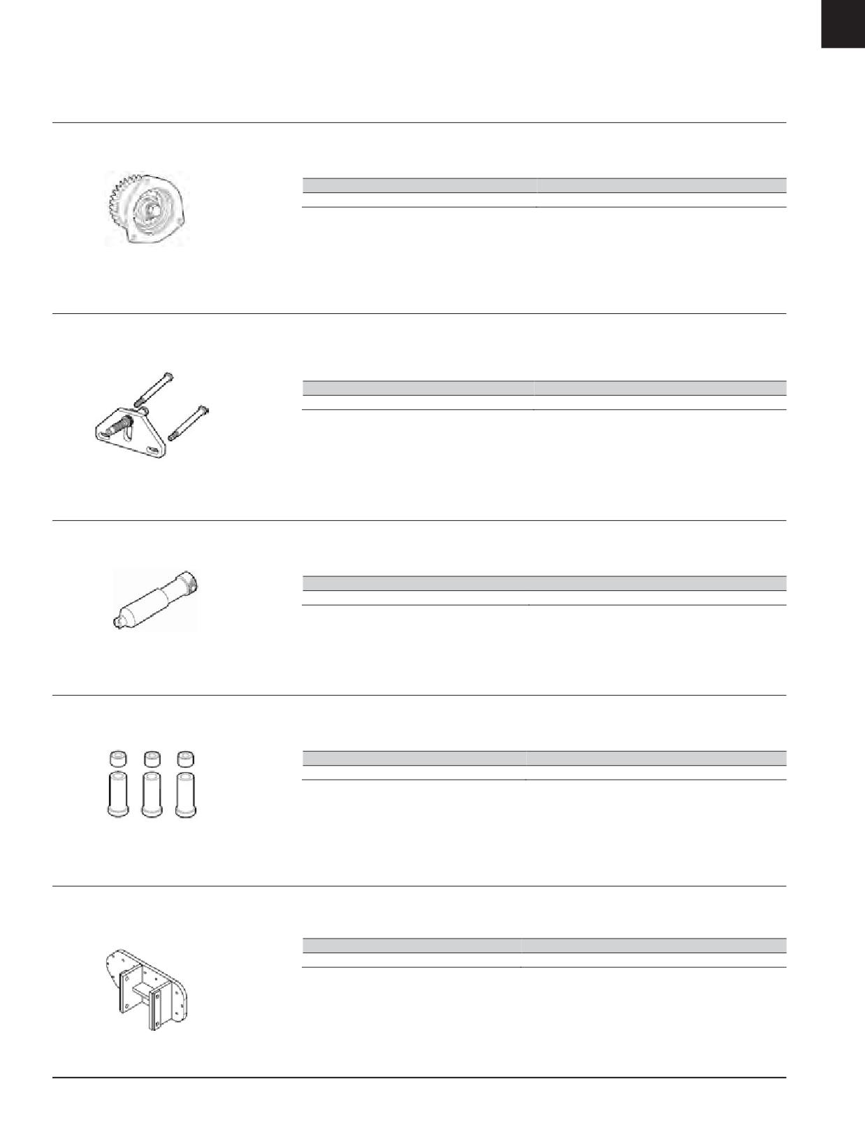
Engine Turning Tool
Model Usage: C8.7 L Engine
• Used to rotate the engine by turning the water
Specifications
pump gear
Warranty: Manufacturer’s
• Weight: 1.8 kg (4 lb)
Part Number
Description
456-7994
Engine Turning Tool
Flywheel Locking Tool
Model Usage: C8.7 L Engine
• Locks the flywheel to the cylinder block so
Specifications
that the flywheel mounting bolts can be
Warranty: Manufacturer’s
• Weight: 1.6 kg (3.5 lb)
removed and installed easily
Part Number
Description
456-7995
Flywheel Locking Tool
Phonic Wheel Timing Tool
Model Usage: C8.7 L Engine
• Used for timing adjustment of Phonic Wheel
Specifications
on camshaft
Warranty: Manufacturer’s
• Weight: 0.2 kg (.5 lb)
Part Number
Description
456-7997
Phonic Wheel Timing Tool
Cylinder Liner Retention Tool
Model Usage: C8.7 L Engine
• Used to hold cylinder liners in place during
Specifications
assembly
Warranty: Manufacturer’s
• Weight: 0.2 kg (.5 lb)
Part Number
Description
456-7999
Cylinder Liner Retention Tool
Rollover Stand Adapter Brackets
Model Usage: C8.7 L Engine
• Used with the 1U-5750 repair stand
Specifications
Warranty: Manufacturer’s
• Weight: 0.2 kg (.5 lb)
Part Number
Description
480-7972
Rollover Stand Adapter Brackets
3-290 JULY 2018 Engine Tools
Engine Tools
C12.9 ENGINE TOOLS
C8.7 ENGINE TOOLS
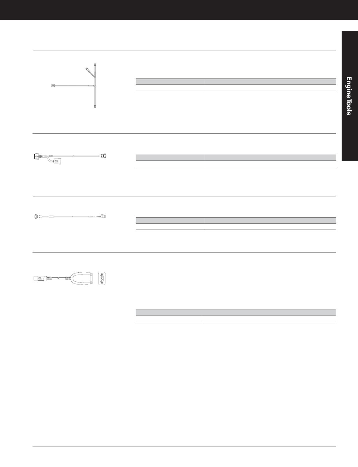
Harness Assembly
Model Usage: C8.7 Marine Engines
• Used to allow technician’s laptop to
• Allows laptop to be connected to the L1 panel
communicate with the system controllers in
on the engine for software updates
Three60 Precision Control
Part No.
Description
430-7691
Harness Assembly
Harness Assembly
Model Usage: C12.9 Marine Engines
• Harness used to connect to controllers via J4
• Allows laptop to be connected to the L1 panel
connection - RS232
on the engine for software updates
Part No.
Description
391-6641
Harness Assembly
Harness Assembly
Model Usage: C12.9 Marine Engines
• Harness used to connect to controllers via J10
• Allows laptop to be connected to the L1 panel
connection - RS485
on the engine for software updates
Part No.
Description
391-6643
Harness Assembly
Communication Adapter
Model Usage: C12.9 Marine Engines
• Communications adapter used to adapt 391-
• LEDs for indicating USB and TxD/RxD activity
6641 and 391-6643 to USB
• 15 KV ESD protection for all serial ports
• Compatible with USB 2.0
• Compliant with RoHS, CRoHS, WEEE
• 921.6 Kbps max baudrate
Reference
• Drivers provided for Windows XP and 7
• UENR0934
• Mini DB9 female-to-terminal block adapter
Part No.
Description
391-6645
Communication Adapter
3-291
JULY 2018 Engine Tools
3-291
Engine Tools
C12.9 ENGINE TOOLS
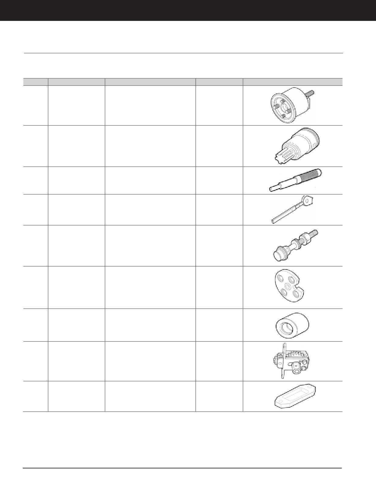
Marine Engine Tooling
Model Usage: C12.9 Marine Engines
Warranty: Manufacturer’s
Part No.
Description
Dimensions
Weight
Image
175 x 175 x 175 mm
487-3123
FrontCrank SealInstaller
5.774 kg (12.729 lb)
(6.88 x 6.88 x 6.88in)
40 x 40 x 100 mm
487-3124
Torx Socket
0.124 kg (0.273lb)
(1.57 x 1.57 x 3.93in)
25.4 x 254 mm
487-3125
Valve Guide Driver
0.001 kg (0.002lb)
(1.00 x 10in)
25.4 x 76.2 x 457.2 mm
487-3126
Belt Tensioner
0.454 kg (1.000lb)
(1.00 x 3.00 x 18.00 in)
Injector Bore Insert for
55 x 55 x 200 mm
487-3127
0.430 kg (0.947lb)
Valve Spring Compressor
(2.16 x 2.16 x 7.87in)
Cap for Valve Spring
130 x 25 x 130 mm
487-3128
0.768 kg (1.693lb)
Compression
(5.11 x 0.98 x 5.11in)
25.4 x 50.8 mm
487-3129
Valve Guide Stop Collar
0.113 kg (0.249lb)
(1 x 2 in)
130 x 130 x 105 mm
487-3130
Flywheel Turning Tool
1.444 kg (3.183lb)
(5.11 x 5.11 x 4.13in)
Spacer for Flywheel
70 x 35 x 140 mm
487-3131
0.312 kg (0.687lb)
Turning Tool
(2.75 x 1.37 x 5.51in)
Continued on next page...
3-292 JULY 2018 Engine Tools
Engine Tools
C12.9 ENGINE TOOLS
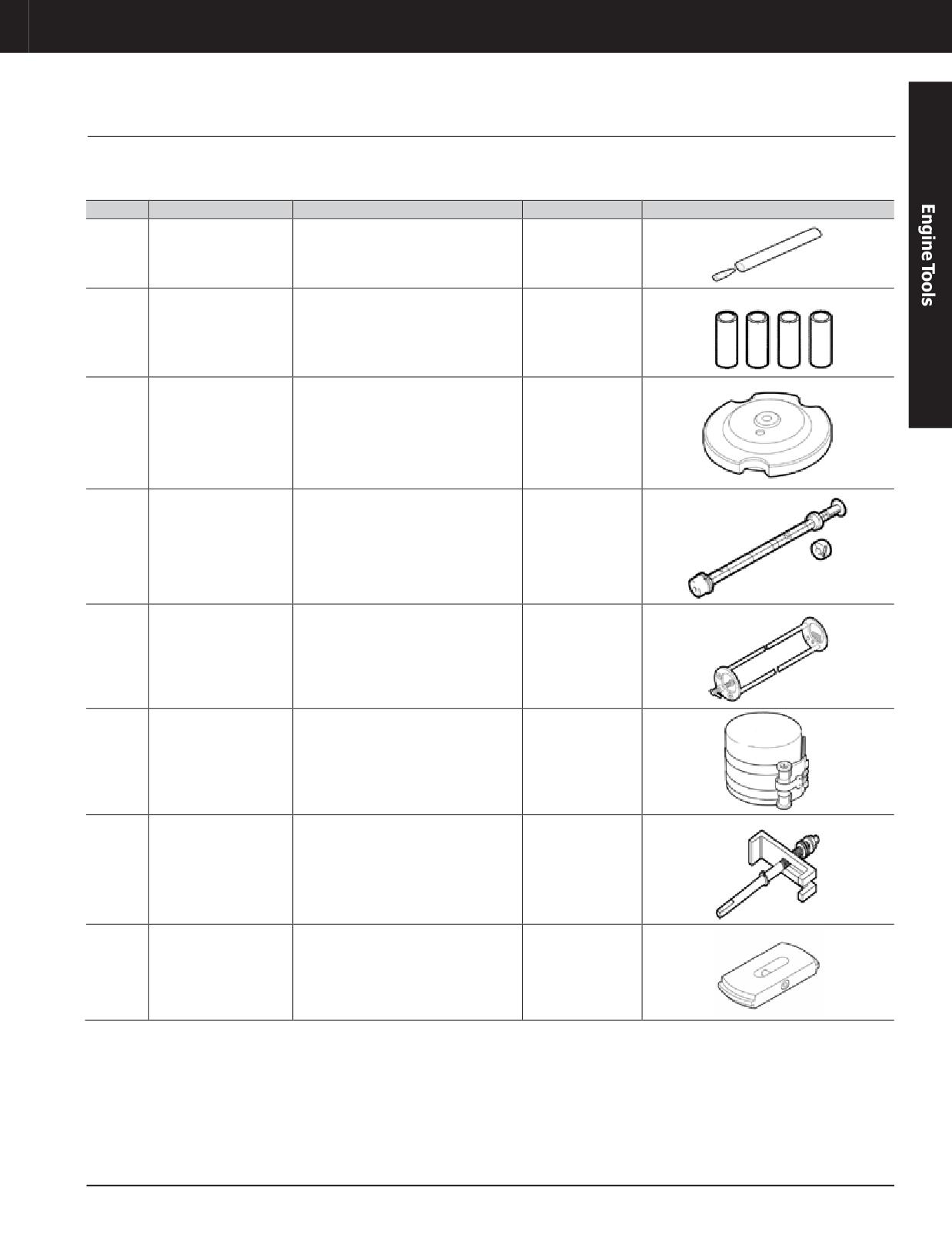
Marine Engine Tooling (Continued)
Model Usage: C12.9 Marine Engines
Warranty: Manufacturer’s
Part No.
Description
Dimensions
Weight
Image
40 x 40 x 200 mm
487-3132
Valve Guide Seal Installer
0.340 kg (0.749lb)
(1.57 x 1.57 x 7.87in)
Spacer -
75 x 55 x 100 mm
487-3133
0.698 kg (1.538lb)
Used With 487-3134
(2.95 x 2.16 x 3.93in)
Cap for Cylinder Liner
180 x 180 x 60 mm
487-3134
Projection Measurement -
2.824 kg (6.225lb)
(7.08 x 7.08 x 2.36in)
Used With 487-3133
Slide Hammer for
1330 x 130 x 130 mm
487-3135
Camshaft Bearing
15.600 kg (34.392 lb)
(52.36 x 5.11 x 5.11 in)
Replacement
Rocker Shaft Remove and
1080 x 140 x 140 mm
487-3136
6.967 kg (15.359 lb)
Install Tool
(42.51 x 5.51 x 5.51 in)
Piston Ring Compressor
90 x 70 x 90 mm
487-3137
0.380 kg (0.837lb)
Tool
(3.54 x 2.75 x 3.54in)
Cylinder Liner Puller -
75 x 75 x 475 mm
487-3138
3.244 kg (7.151lb)
Used With 487-3139
(2.95 x 2.95 x 18.70 in)
Plate Used with Cylinder
55 x 55 x 200 mm
487-3139
1.108 kg (2.442lb)
Liner Puller Tool
(2.16 x 2.16 x 7.87in)
Continued on next page...
JULY 2018 Engine Tools
3-293
Engine Tools
C12.9 ENGINE TOOLS
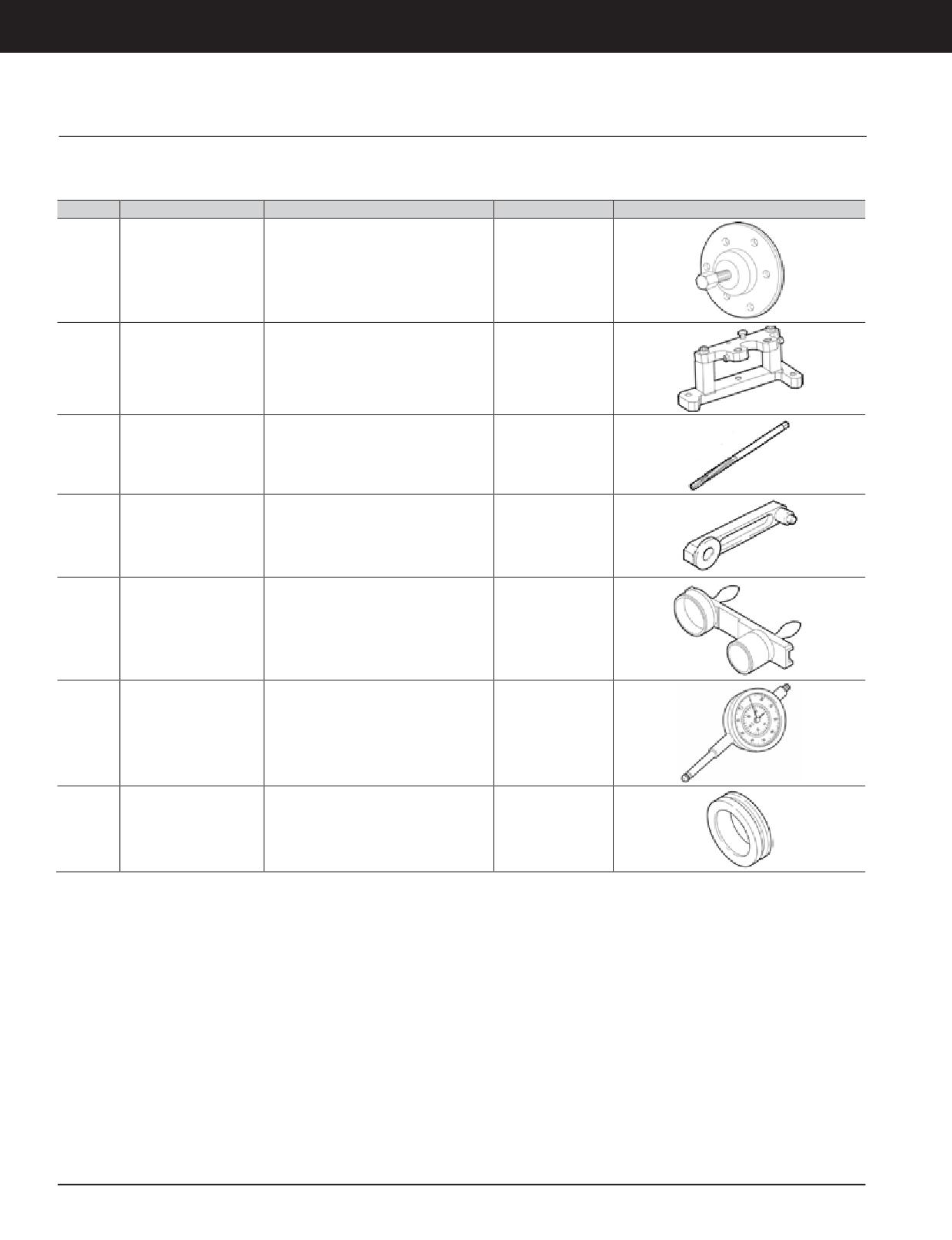
Marine Engine Tooling (Continued)
Model Usage: C12.9 Marine Engines
Warranty: Manufacturer’s
Part No.
Description
Dimensions
Weight
Image
High Pressure Pump Gear
130 x 130 x 105 mm
487-3140
0.907 kg (1.999lb)
RemovalTool
(5.11 x 5.11 x 4.13in)
Fixture for Checking
155 x 110 x 70 mm
487-3141
Engine Timing -
2.268 kg (5 lb)
(6.10 x 4.33 x 2.75in)
Used With 487-3146
40 x 40 x 200 mm
487-3143
Valve Guide Reamer
0.1 kg (0.22 lb)
(1.57 x 1.57 x 7.87in)
CamGearBacklashTool
70 x 70 x 270 mm
487-3144
1.410 kg (3.108lb)
(Cam and Idler Gear)
(2.75 x 2.75 x 10.62 in)
CamGearBacklashTool
195 x 105 x 340 mm
487-3145
(Cam Gear and High
1.361 kg (3 lb)
(7.67 x 4.13 x 13.38 in)
Pressure Pump)
Dial Indicator for Engine
85 x 33 x 198 mm
487-3146
Timing -
0.215 kg (0.473lb)
(3.34 x 1.29 x 7.79in)
Used With 487-3141
Front Oil Seal Installation
135 x 50 x 135 mm
487-3147
1.178 kg (2.597lb)
Tool
(5.31 x 1.96 x 5.31in)
3-294 JULY 2018 Engine Tools
Engine Tools
3600 ENGINE TOOLS
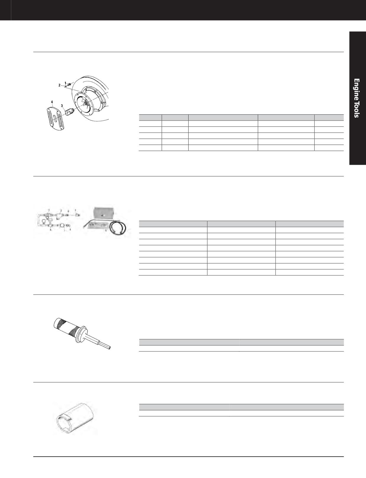
Turbocharger Blocking Tool
Model Usage: 3600 Engines
• Prevents rotation of turbocharger impeller
• When rotation of turbocharger is prevented,
(allows emergency engine operation at
air flow through turbo is maintained and
Warranty: Caterpillar ®Six Months
reduced power)
lubricating oil flow must be stopped; (for
procedure to stop lubricating oil, refer to
• To stop rotation, disconnect air inlet; install
Special Instruction SEHS8704) The output
key (3) into impeller bushing; secure with
power of the engine must then be limited so
plate (4)
exhaust gas temperature at cylinders does not
exceed 480°C (900°F)
Item
Part No.
Description
Size
Qty.
—
8T-9209
Turbocharger Blocking Tool
-
-
1 a
0S-1595
Bolt
1/2 - 13 x 11/4 in
4
2 a
0S-1593
Lock Washer
-
4
3
-
Key
-
-
4
-
Plate
-
-
a. Items are not part of 8T-9209
Turbocharger Wash Group
Model Usage: 3600 Engines
• Used to remove deposits which form on the
• Use only with fresh, clean water (additives,
diffuser and turbine blades when an engine is
solvents, salt, and dirt in water tend to form
Warranty: Caterpillar ®Six Months
operated on heavy fuels
deposits on diffuser and turbine blades)
• Washer provides cleaner turbines resulting in
increased performance of turbocharger
Item
Part Number
Description
—
137-7024
Turbocharger Wash Group
1
130-3298
Flow Meter
2
130-3299
Screen
4
130-3301
Needle Valve
5
130-3295
Quick Disconnect Nipple
6
130-3296
Quick Disconnect Nipple
7
130-3297
Quick Disconnect Coupler
8
129-4891
Hose Assembly
Valve Seat Driver
Model Usage: 3600 Engines
• Used to install water-cooled valve seat inserts
• Overall length: 355.0 mm (14.0 in )
Warranty: Caterpillar ®Six Months
• Serves as guide and driver, helping to
• Diameter of knurl handle: 65.0 mm (2.5 in )
prevent insert damage during installation
and ensuring insert is uniformly installed in
cylinder head
Part Number
Description
4C-8769
Valve Seat Driver
Cylinder Head Stud Socket Assembly
Model Usage: 3618 Engines
• Used to quickly remove and install cylinder
• Also known as a nut spinner
head nuts after tensioning is released
Warranty: Caterpillar ®Six Months
Part Number
Description
184-3131
Cylinder Head Stud Socket Assembly
3-295
3-295
Engine Tools
3600 ENGINE TOOLS
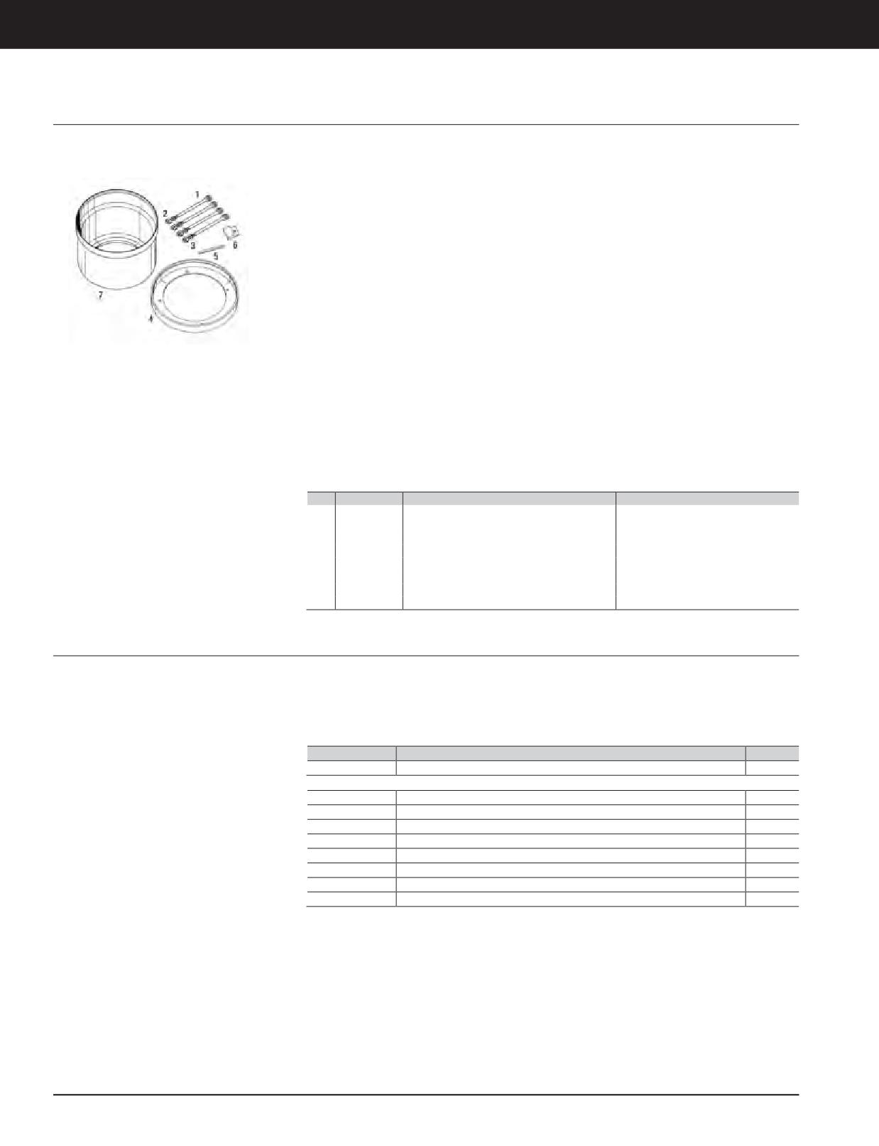
Wear Sleeve and Seal Installer, Stud Assembly, Distorter Block
Model Usage: 3600 Engines
• Used to remove and install crankshaft wear
• Making four indentations around the
sleeve - essential to correctly remove and
crankshaft wear sleeve should allow sleeve to
Warranty: Caterpillar ®Six Months
install sleeve without damage to sleeve or
easily slide off crankshaft
crankshaft
Installation
• 1U-6241 installs seal after wear sleeve is
1.
Install wear sleeve in installer.
installed
2.
Thread four studs into crankshaft.
Removal
3.
Install sleeve and installer onto studs.
• Use the 121-7700 Distorter Block with
4.
Install washers and nuts.
5P-7409 Distorter
5.
Tighten nuts to pull wear sleeve onto
• Distorter block bolts directly to engine
crankshaft.
housing using one of the cover mounting
holes and bolt
6.
When inside face of installer bottoms
against end of crankshaft, sleeve is installed
• Tools work together to make an indentation in
to correct depth.
the sleeve (helps to loosen sleeve from
crankshaft)
7.
Install seal.
• Distorter tool is rotated between distorter
Reference
block and wear sleeve to create an
• SENR3594, Service Manual Module,
indentation in the metal (similar to using a
Disassembly and Assembly
hammer and chisel to make the indentation)
Item
Part Number
Description
Size
Threads on large end: 11/8 - 12,
1
121-7705
Stud Assembly
Threads on small end: 1/2 - 13
2
1F-7958
Full Nut (1/2 - 13) (fork mounting hardware)
1/2-13
3
5P-8245
Hard Washer
-
4
200-5958
Wear Sleeve Installer
-
5
5P-7409
Sleeve Distorter
-
6
121-7700
Distorter Block
-
7
1U-6241
Seal Installer
-
Overhaul Protection Kit
Model Usage: 3600 Engines
• Contains covers and plugs for one cylinder
• Easily installed and quickly removed
Warranty: Caterpillar ®Six Months
• Protect fuel lines and openings in cylinder
• 4 plastic web sleeves in each kit reduce
head from dust and dirt and serve as moisture
impact damage to threads of cylinder head
seal while engine is overhauled
studs
Part Number
Description
Quantity
229-3639
Overhaul Protection Kit
-
Service/Repair Parts
229-3608
Protective Plug, Cylinder Liner and Bore
2
4C-9517
Protective Plug, injector hole in head
1
4C-9518
Protective Plug, 3/16 - 16 thd, fuel lines
4
4C-9519
Protective Cap, 3/16— 16 thd, fuel line connectors on head and block
4
4C-9521
Protective Cap, 9/16 - 18 thd, oil line connectors in head and block
2
4C-9524
Protective Web Sleeve, threads on cylinder head studs
4
6P-6605
Plug, intake hole in block
1
7H-2902
Protective Plug, water jacket in block
4
3-296 JULY 2018 Engine Tools
Engine Tools
3600 ENGINE TOOLS
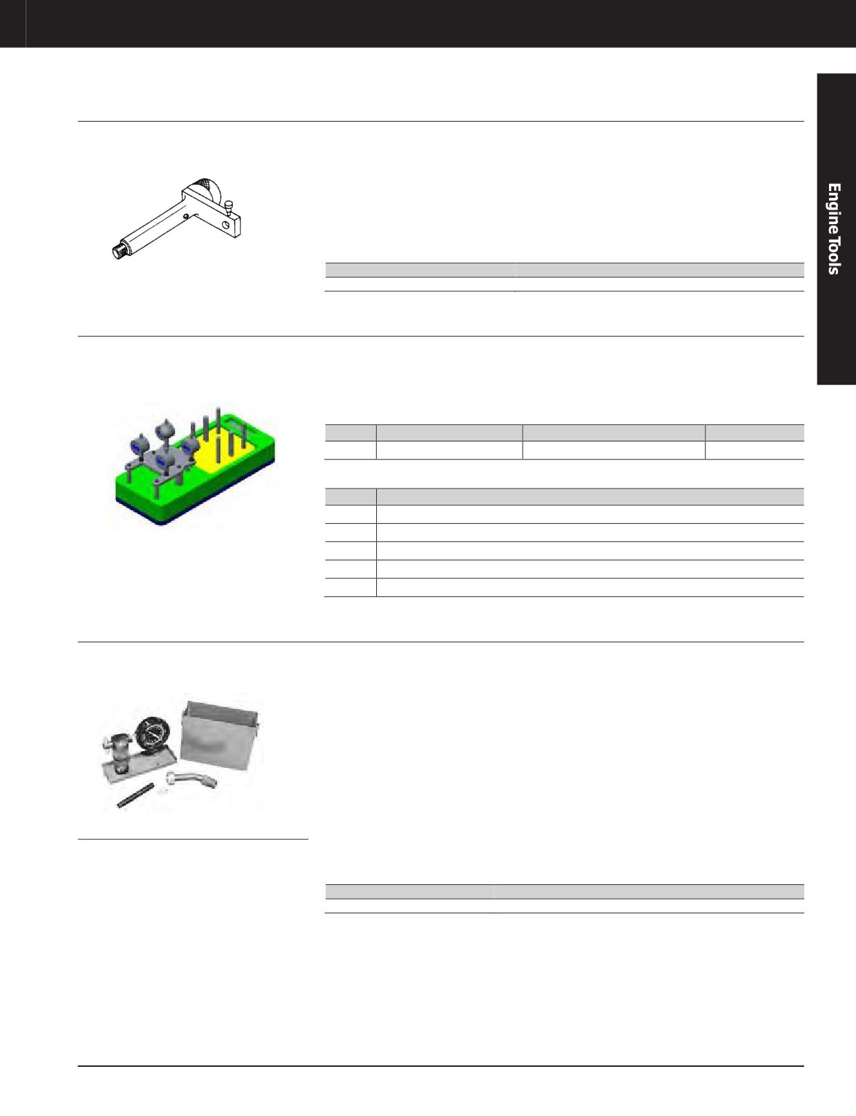
Valve Lash Tool
Model Usage: 3600 Engines
• Used to easily check and adjust valve lash
• 11.11 cm (4 3/8 in) fabricated steel bracket
clearance of intake and exhaust valve
with: 1/4 - 24 plastic thumb screw to hold
Warranty: Caterpillar ®Six Months
a dial indicator in place 3/8 - 16 bolt with
• Part of 4C-6594 Timing and Fuel Setting Tools
38.1 mm (1 1/2 in) diameter knurled knob for
• Used with 6V-3075 Dial Indicator and 8S-3675
ease of installing to valve rocker cover base
Contact Point (parts of 4C-6594 Tool Group);
both can be secured in valve lash tool by
tightening nylon thumb screw
Part Number
Description
4C-6593
Adjusting As - Valve Lash
Valve Recession Tool Kit
Model Usage: G3600 Engines
• Measures valve recession on four valves
• This method requires rocker arms to be
simultaneously
removed.
Warranty: Caterpillar ®Six Months
• Not mounting the tool to the head provides
additional accuracy.
Part No.
Description
Dimensions
Weight
504-1405
Valve Recession Tool Kit
600 x 251 x 312 mm (24 x 10 x 13 in)
15 kg (33.07lb)
Serviceable Parts
Part No.
Description
504-1406
Calibration Block Assembly
504-1407
Dial Indicator
504-1408
Block Gauge Assembly
6V-3186
Collet
6V-7918
Wrench
Cylinder Pressure Measuring Indicator Group, 3000 PSI
Model Usage: 3600 Engines
• Troubleshooting tool used to check cylinder
• K-107 cylinder pressure indicator
pressure on 3600 Family Diesel Engines
manufactured by Kiene Diesel Accessories,
Warranty: Manufacturer’s Six Months
Inc.
• Easily provides relative average peak cylinder
pressure on running engine
• Equipped with 3 1/2 inch Zytel nylon Bezel
and case, threaded Bezel, Bourdon tube
• Not recommended for use on other than
gauge, dual range 0 through 3000 PSI and 0
diesel engines because static pressure
through 210 kg/cm², metal case and service
indication would require too much tapping to
tool
bring pointer to correct reading
• Kiene AX-13A standard indicator connection
• Used with 7E-1699 Manual Valve Group
(M) by 1 1/16-10 Whitworth (F), wing nut and
designed so any movement of valve stem
plug, 45° bend, 15.2 cm (6 in) long
REPAIR AND SERVICE
due to engine vibration tightens valve
Kiene Diesel Accessories, Inc. 325 So. Fairbanks Street
stem against its seat; prevents valve from
Addison, IL 60101
accidentally opening during engine operation
Phone: 708-543-5950
Fax: 708-543-5953
Part Number
Description
4C-6585
Cylinder Pressure Measuring Indicator Group
JULY 2018 Engine Tools
3-297
Engine Tools
3600 ENGINE TOOLS
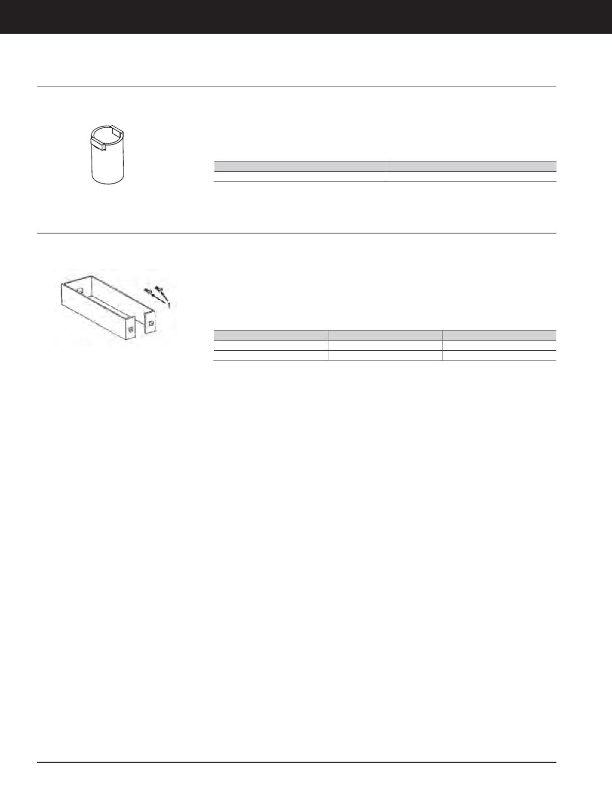
Socket
Model Usage: All 3600 Engines except 3618
• Used for removal and installation of cylinder
• Used with hydraulic stud tensioners of
head nuts
4C-5858 Tool Group
Warranty: Caterpillar ®Six Months
• Saves time by installing nuts prior to use of
• Maximum torque: 340 N·m (250 ft-lb)
tensioners and removing nuts after releasing
torque
Part Number
Description
4C-6987
Socket
Safety Retainer Group
Model Usage: 3600 Engines
• Used for disassembly and assembly of
• If the pulling rod accidentally breaks and
cylinder head assembly
the retainer becomes deformed, the retainer
Warranty: Caterpillar ®Six Months
should be replaced.
• Steel strap safety retainer for pulling rod in
case pulling rod accidentally breaks
• Dimensions (thickness x width x length): 3.175
x 44.45 x 290 mm (1/8 x 1 3/4 x 11.4 in) long
• Fits around 316-1493 Hydraulic Puller
(length allows full stroke of 316-1493 Puller
Assembly (fastened to bottom with 2 screws)
Assembly)
Item
Part Number
Description
—
4C-9839
Safety Retainer Group
1
2M-5139
Screw (2)
3-298 JULY 2018 Engine Tools
Engine Tools
3600 ENGINE TOOLS
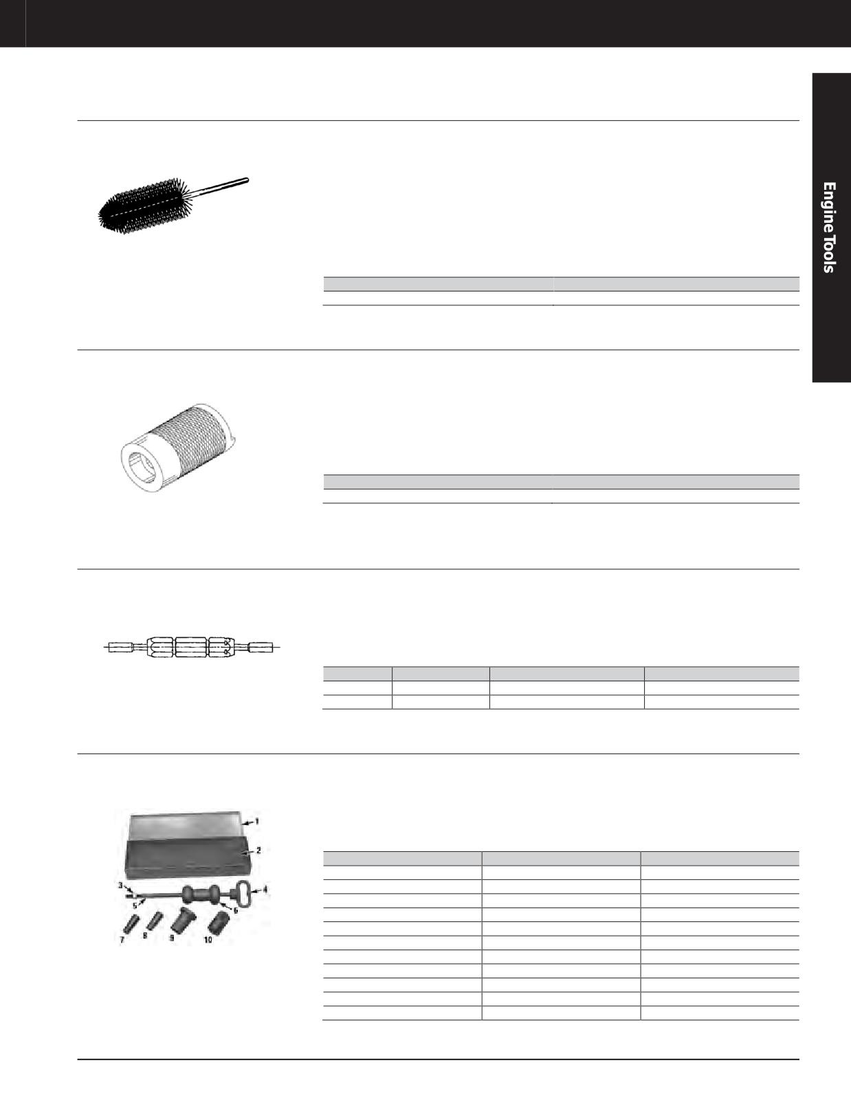
Injector Seat Cleaning Brush
Model Usage: 3600 Engines
• Used to clean injector bore seats (also part of
Specifications
9U-5106 Diesel Tool Group)
Warranty: Caterpillar ®Six Months
• Overall length: 31.8 cm (12.5 in)
• Used with 1/4 inch drive drill
• Brush diameter: 47.6 mm (1.88 in)
• Made of stainless steel - provides best
• Wire diameter: 0.25 mm (0.010 in)
cleaning results without causing damage to
injector bore seat (other brushes may not have
the stiffness to clean or be too stiff and cause
damage)
Part Number
Description
130-6993
Injector Bore Brush
Bridge Dowel Gauge
Model Usage: 3600 Engines
• Used to check straightness and projection of
• Also used to check projection of dowel above
4W-5441 Bridge Guide Dowel
cylinder head
Warranty: Caterpillar ®Six Months
• Bridge dowels that are not straight will not go
• Gauge quickly and accurately measures 105
through gauge and must be replaced (fast and
± 2 mm (4.1 ± 0.08 in) height requirement for
easy method of determining reusability)
bridge guide dowels
• Inside diameter: 19.09 mm (0.752 in)
Part Number
Description
130-2534
Bridge Dowel Gauge
Valve Guide Gauges
Model Usage: 3600 Engines
• Used to check wear and correct installation of
• 9U-6399 Gauge used to check newly installed
valve guide
valve guides (passing gauge through valve
Warranty: Caterpillar ®Six Months
guide determines straightness (deformation)
• 9U-6401 Gauge quickly gives use again or do
of inside diameter and shows if an area is
not use again status of valve guides
below minimum diameter)
Part Number
Description
Diameter x Length (Go)
Diameter x Length (No-Go)
9U-6399
Valve Guide Gauge
16.003 x 175 mm (0.630 x 6.9 in)
16.059 x 50.8 mm (0.6322 x 2.0 in)
9U-6401
Valve Guide Gauge
16.106 x 50.8 mm (0.634 x 2.0 in)
16.209 x 50.8 mm (0.6381 x 2.0 in)
Dowel Puller Group
Model Usage: 3600 Engines
• Used for pulling 15.875 mm (5/8 in) and
Specifications
19.5 mm (3/4 in) dowels
Warranty: Caterpillar ®Six Months
Stand height: 88.9 mm (3.5 in)
• Makes the job quick and easy
Shaft length: 452.6 mm (17.81 in)
Slide hammer weight: 2.72 kg (6 lb)
Item
Part Number
Description
—
1U-9570
Dowel Puller Group
1
1U-9568
Metal Box (not serviced)
10
1U-9577
Forcing Collar
2
1U-9569
Foam Block (not serviced)
3
8T-9413
Nut (not serviced)
4
1U-9571
Handle
5
1U-9574
Shaft
6
1U-9575
Slide Hammer
7
1U-9573
Extractor, 19.05mm (3/4in)
8
1U-9572
Extractor, 15.875mm (5/8in)
9
1U-9576
Dowel Retriever Stand
JULY 2018 Engine Tools
3-299
Engine Tools
3600 ENGINE TOOLS
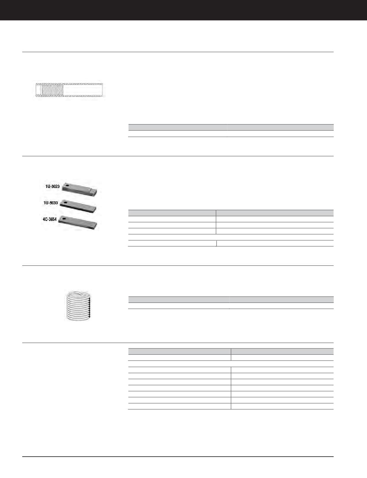
Thread Repair Insert
Model Usage: 3600 Engines
• Replaces disc. 4C-6409 Thread Repair Insert
Reference
Warranty: Caterpillar ®Six Months
• Used to repair stud holes with damaged
• SEBF8151, Guideline for Reusable Parts
threads (only one of four holes per head can
Specifications
be repaired using this insert)
• Outsidethread: 2-12
• Install by drilling damaged hole to 23.41 mm
• Inside thread: 1 5/8 - 12
(1 59/64 in) and threading hole with 2-12 tap
• Overall length: 270.0 mm (10.6 in)
• Drill: 4C-6415 Drill
• Threaded repair insert is locked into place
• Tap with pilot: 4C-6417 Tap
with 9S-3265 Retaining Compound
• Extension tap: 4C-6416 Tap
Part Number
Description
128-5113
Thread Repair Insert
Ring Groove Gauges
Model Usage: 3600 Engines
• Used to check piston ring groove wear to
• Gauges clearly marked with “top and second
determine reusability of piston
ring”, “third ring”, and “oil ring” for easy
Warranty: Caterpillar ®Six Months
identification
• Simple to use. If the scribe line is visible, then
the piston ring groove is good. If the line is
• Made from heat treated steel for better wear
not visible, then the piston is nonreusable.
resistance
• 3 gauges (checks all four piston ring grooves)
• Size (L x W): 75 x 19 mm (3.0 x 0.8 in)
Part Number
Description
1U-9029
Ring Groove Gauge (oil ring)
1U-9030
Ring Groove Gauge (third ring)
4C-3654
Ring Groove Gauge (top and second ring)
Not shown
197-3710
Ring Groove Gauge (top and second ring), 3618 only
Threaded Insert
Model Usage: 3600 Engines with Turbochargers
• Used to repair stripped or damaged threads in
• Used with 4C-9730 Tap and 8T-2793
turbocharger housings
Installation Tool
Warranty: Caterpillar ®Six Months
• Will withstand 540°C (1000°F) temperatures
• Thread specification: M10 x 1.5
Part Number
Description
133-1531
Threaded Insert
Spark Ignited Tool Group (9U-5107)
Model Usage: 3600 Series Spark Ignited Engines
Part Number
Description
9U-5107
Spark Ignited Tool Group
Warranty: Caterpillar ®Six Months
The 9U-5107 Group consists of the following tools (each is discussed separately)
369-2607
Digital Indicator
4C-4601
Spark Plug Socket
4C-6593
Adjusting As - Valve Lash
4C-8568
Liner Puller Group
4C-9043
Compressor Group
5P-4160
Point - Indicator Contact, 19.05 mm (0.75 in) long
9U-5156
Cleaning Tool Group
3-300 JULY 2018 Engine Tools
Engine Tools
3600 ENGINE TOOLS
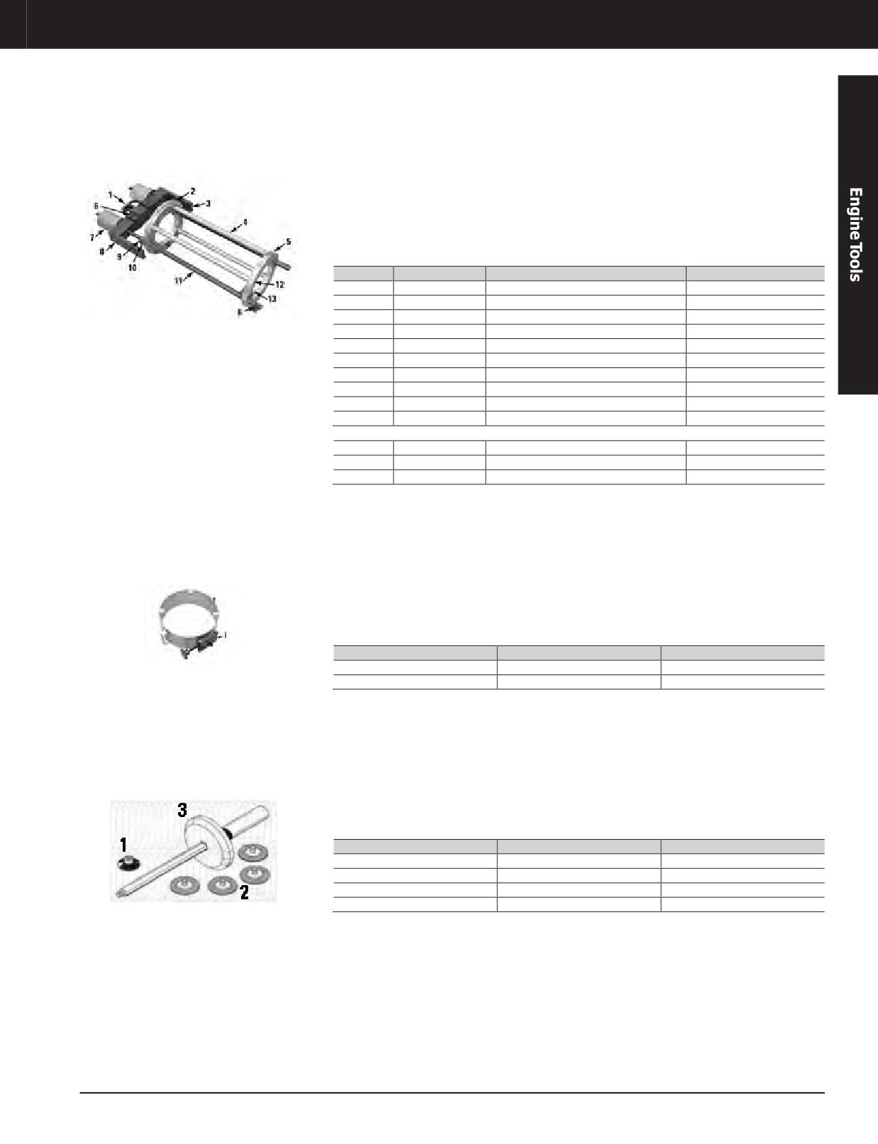
Liner Puller Group (part of 9U-5107 Group)
Model Usage: 3600 Spark Ignited Engines
• Used to remove and install cylinder liner using
• Used with 350-7768 Hydraulic Pump (115 Volt)
hydraulic pressure (hoist attaches to puller to
or 350-7769 Hydraulic Pump (230 Volt); other
Warranty: Caterpillar ®Six Months
easily handle tool and cylinder liner)
required tooling is 8T-3035 Lines Group and
8T-0820 Pressure Gauge
• Hydraulic pump connects to two hydraulic
puller assemblies for a combined pulling force
References
of 11 tons at 34,474 kPa (5000 PSI)
• SENR4255, Service Manual
• SENR5500, Service Manual
Item
Part Number
Description
Qty.
—
4C-8568
Liner Puller Group
-
2
4C-8565
Top Ring
-
4
6V-7069
Rod Spacer
4
5
4C-8566
Bottom Ring
-
6
2J-5245
Bolt - Hex Socket Head
4
7
316-1493
Hydraulic Puller Group
2
10
4B-5278
Washer
2
11
299-5231
Leg Assembly
2
12
4D-3120
Bolt
8
13
4H-6996
Spring Pin
8
Not shown
-
1B-4331
Nut
2
—
2K-6073
Bolt
4
—
4B-5276
Bolt Washer
2
Piston Ring Compressor Group (part of 9U-5107 Group)
Model Usage: 3600 Spark Ignited Engines
• Installs piston and connecting rod assemblies
• 4 tabs for support while securing to piston
Warranty: Caterpillar ®Six Months
• Band-type ring compressor for 30cm piston
• 2 handles for easy piston and ring positioning
• Over-center adjustable lock
References
• Proper seating of band assembly on cylinder
• SENR4255, Service Manual
liner to minimize possibility of ring breakage
• SENR5535, Service Manual
Item
Part Number
Description
—
4C-9043
Compressor Group
1
6V-4027
Handle Assembly
Cleaning Tool Group (part of 9U-5107 Group)
Model Usage: 3600 Spark Ignited Engines
• Cleans prechamber seats on cylinder heads
Specifications
Warranty: Caterpillar ®Six Months
• Used with 3/8 inch drive speed handle (easily
• Extension length: 23 cm (9.0 in)
removes rust with 10 to 20 turns of handle)
• Major OD: 78 mm (3.0 in)
• Drive end: 3/8 in square (female)
• Pilot helps to keep tool aligned
• Extension end: 1/4 - 20 thd
Item
Part Number
Description
—
9U-5156
Cleaning Tool Group
1
150-5431
Pad Cut Down Disc a
2
150-5483
EXL Unitized Roloc Disc
3
1U-9023
Pilot Assembly
a. Warranty: Manufacturer’s, 120-Day
JULY 2018 Engine Tools
3-301
Engine Tools
3600 ENGINE TOOLS
Basic Tool Group (9U-5105)
Model Usage: 3600 Engines
Part Number
Description
Qty
9U-5105
Basic Tool Group
-
Warranty: Caterpillar ®Six Months
The 9U-5105 Group consists of the following tools (each is discussed separately)
121-7700
Distorter Block
-
121-7705
Stud Assembly
-
126-6918
Head Lifting Bracket
-
126-6919
Head Lifting Bracket
-
126-6920
Handle Rod
-
134-0932
Main Bearing Driver
-
136-1452
Internal Pliers Assembly
-
439-3938
Bracket Assembly - Link
2
439-3939
Link Bracket
2
439-3940
Bracket - Link
2
145-5190
Piston Support Group
-
191-1135
Cylinder SpaceAssembly
2
1F-7958
Full Nut (1/2 - 13) (fork mounting hardware)
-
1P-7405
Eyebolt
-
1P-7407
Eyebolt (1/2 - 13)
-
1P-7409
Eyebolt
-
1U-8692
Piston Pin Guide
-
1U-9392
Damper Guide Pin
2
1U-9393
Damper Guide Pin
2
1U-9824
ToolGroup
-
200-5958
Wear Sleeve Installer
-
235-0632
Cylinder Installation Tool Group
-
4C-6173
Fuel Drain Tray Assembly
-
4C-6357
Guide Group
-
4C-9426
Damper Guide Pin
-
4C-9451
Idler Rear Wrench
-
4C-9452
Idler Rear Wrench
-
4C-9818
Hex Shank
-
4C-9819
Universal Joint
-
5D-1972
Bolt (2)
-
5P-7409
Sleeve Distorter
-
5P-8245
Hard Washer
-
8T-0890
Puller Group
-
8T-0914
Flywheel Guide Pin
2
8T-0960
Handling Tool Group
-
8T-0970
CamshaftBearingToolGroup
-
8T-3022
Rod Guide Group
-
8T-3029
Camshaft Segment Support Group
-
8T-3034
Water Pump Seal Driver
-
9U-5932
Extension Camshaft Torque
-
9U-5981
Snap Ring Retainer
-
9U-6244
Support
-
9U-6248
Guide Bolt
3
9U-6251
Suspension Yoke Assembly
-
9U-6461
Phoenix Screwdriver
-
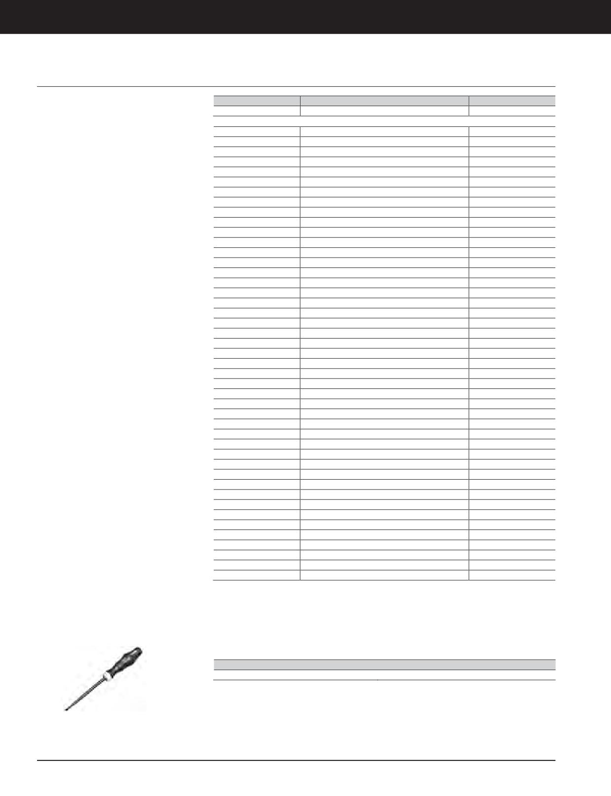
Engine Tools, Phoenix Screwdriver (Part of 9U-5105 Group)
Model Usage: 3600 Engines
• Used to tighten Phoenix connectors to correct
• Length: 180.0 mm (7.0 in)
torque (prevents over-torque and thus damage
Warranty: Manufacturer’s
to terminals)
Part Number
Description
9U-6461
Phoenix Screwdriver
3-302 JULY 2018 Engine Tools
Engine Tools
3600 ENGINE TOOLS
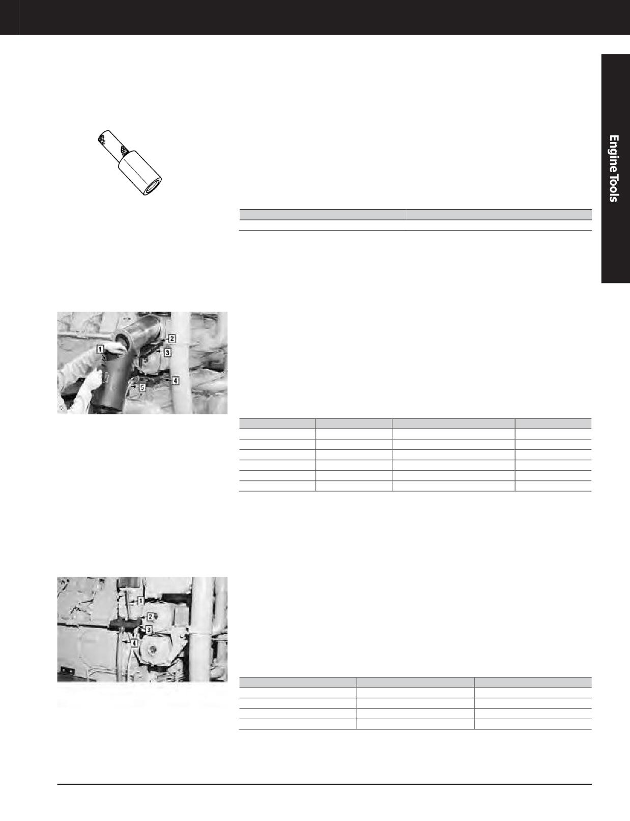
Basic Tool Group for Miscellaneous Tools, Water Pump Seal Driver (Part of 9U-5105 Group)
Model Usage: 3600 Engines
• Used to seat ceramic ring and rubber seat
References
into water pump housing (knurled handle for
Warranty: Caterpillar ®Six Months
• SENR3594, Service Manual Module of
better grip)
SENR3590 Service Manual
• Also installs carbon seal onto pump shaft
• SENR3600, Service Manual Module of
(pressed onto shaft until light contact with
SENR3595 Service Manual
ceramic seal face is made)
•
SENR4259, Service Manual Module of
• Length: 210.0 mm (8.3 in)
SENR4255 Service Manual
• Seal diameter: 63.0 mm (2.5 in)
Part Number
Description
8T-3034
Water Pump Seal Driver
1U-9824 Oil Drain Tool Group (Part of 9U-5105 Group)
Model Usage: 3600 Engines
• Used to drain oil from filter housing (keeps
• Drain trays and scoop made from heavy-gauge
engine clean, captures all used oil, reduces
sheet metal
Warranty: Caterpillar ®Six Months
cleanup cost)
• Scoop diameter: 203 mm (8.0 in)
• 9U-9822 and 9U-9821 Trays catch oil; 5N-5566
References
Hose routes it to a container (trays attach to
filter housing with four 9S-8752 Nuts)
• SENR3594, Service Manual Module of
SENR3590 Service Manual
• 1U-9823 Scoop provides convenient way to
carry used filters to a disposal area (filter is
• SENR3600, Service Manual Module of
also too hot to handle without scoop)
SENR3595 Service Manual
• Allows filter replacement while engine is
• SENR4259, Service Manual Module of
running
SENR4255 Service Manual
Item
Part Number
Description
Qty.
—
1U-9824
ToolGroup
-
1
1U-9823
Filter Scoop Assembly
-
2 a
9S-8752
Nut - Full (3/8 - 16)
2
3
1U-9822
Tray Assembly, Upper
-
4
1U-9821
Tray Assembly, Lower
-
5 a
5N-5566
Hose (not part of 4C-6173)
a. Not part of 1U-9824
Fuel Drain Tray Assembly (Part of 9U-5105 Group)
Model Usage: 3600 Engines
• Used to drain fuel from filter housing (keeps
• Allows filter replacement on running engine
engine clean, captures all fuel, reduces
Warranty: Caterpillar ®Six Months
• Heavy-gauge sheet metal with 25 mm spout
cleanup costs)
References
• 7V-0198 Hose and 4C-6173 Tray catches fuel;
5N-5566 Hose routes it to a container (tray
• SENR3594, Service Manual Module of
attaches with two 4F-4879 Bolts)
SENR3590 Service Manual
• 1U-9823 Scoop from 1U-9824 Oil Drain Tool
• SENR3600, Service Manual Module of
Group provides convenient way to carry used
SENR3595 Service Manual
filters to a disposal area
• SENR4259, Service Manual Module of
SENR4255 Service Manual
Item
Part Number
Description
1
7V-0198
Hose (not part of 4C-6173 )
2
4F-4879
Bolt, (2) (not part of 4C-6173 )
3
4C-6173
Fuel Drain Tray Assembly
4
5N-5566
Hose (not part of 4C-6173 )
JULY 2018 Engine Tools
3-303
Engine Tools
3600 ENGINE TOOLS
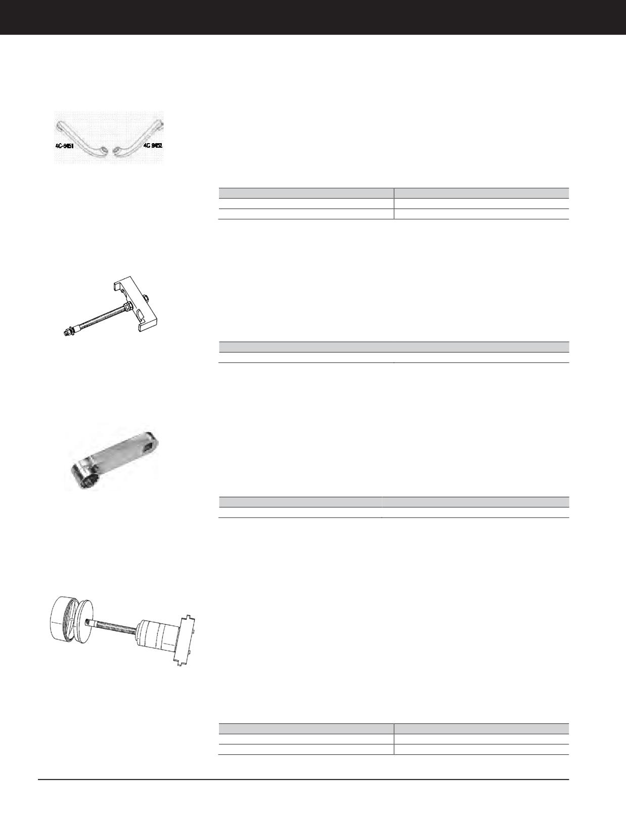
Idler Gear Wrench (Part of 9U-5105 Group)
Model Usage: 3600 Engines
• Used to remove and install bolts on rear idler
• 3/4"square-drive to connect torquewrench
gear of 3612 and 3616 Engines (accesses hard
• 2 opposite L-shaped wrenches 12-point
to reach bolts)
socket: 1 1/8 inch Square drive end: 3/4 inch
• Torque extensions of 101.6 and 254 mm (4
Reference
and 10 in) etched on each wrench so correct
torque can be calculated (SEHS7150 Special
• SENR3594, Service Manual Module of
Instruction for correct torque wrench setting)
SENR3590 Service Manual
Part Number
Description
4C-9451
Idler Rear Wrench
4C-9452
Idler Rear Wrench
Puller Group (Part of 9U-5105 Group)
Model Usage: 3600 Engines
• Removes rotor cover from centrifugal oil filter
• SENR3600, Service Manual Module of
(allows replacement of 7C-8390 Rotor Liner)
SENR3595 Service Manual
References
Specifications
• SENR3594, Service Manual Module of
• Bolt size and length: 1/2 - 13 x 10.5 in
SENR3590 Service Manual
• Nuts (3): 1/2 - 13 thd
• Bridge: 35 x 40 x 169 mm (1.4 x 1.6 x 6.7 in)
Part Number
Description
8T-0890
Puller Group
Camshaft Torque Extension (Part of 9U-5105 and 9U-5106 Groups)
Model Usage: 3600 Engines
• Used to remove and install bolts retaining
• Designed with minimum clearance to fit onto
thick-flange camshaft segments
the bolts (conventional sockets cannot reach
the bolts)
• Using the extension requires a calculation to
determine the correct torque; the extension
Specifications
uses a 100mm (4 in)lever arm(use Form
• Square drive: 1/2 in
SEHS7150 to calculate the proper torque
• Socket (12 point): 15/16 in
wrench setting)
• Length of extension: 100 mm (4.0 in)
Part Number
Description
9U-5932
Extension Camshaft Torque
Camshaft Bearing Tool Group, 3600 Engines (Part of 9U-5105 Group), Camshaft Bearing Tool
Group, 3618 Engines (Not Part of 9U-5105 Group)
Model Usage: 3600 Engines
• Removes/installs camshaft bearings (not
SENR3590 Service Manual
possible by any other means)
• SENR3600, Service Manual Module of
SENR3595 Service Manual
• Disc. 8T-0968 Bridge will pilot in bearing
• SENR4259, Service Manual Module of
bore on one side and when reversed, pilot in
SENR4255 Service Manual
cylinder block bearing bore on other side
Specifications
• Used with 350-7768 Hydraulic Pump (115 V)
or 350-7769 Hydraulic Pump (230 V); other
• Cylinder:
required tooling is 8T-3035 Lines Group and
- Capacity: 180 kN (20 ton)
8T-0820 Pressure Gauge
- Stroke: 76 mm (3.0 in)
Assembled Camshaft Bearing
- Max. oper. pressure: 69,000kPa (10,000PSI)
Tool Group
References
• SENR3594, Service Manual Module of
Part Number
Description
156-7155
CamshaftBearingToolGroup
8T-0970
CamshaftBearingToolGroup
3-304 JULY 2018 Engine Tools
Engine Tools
3600 ENGINE TOOLS
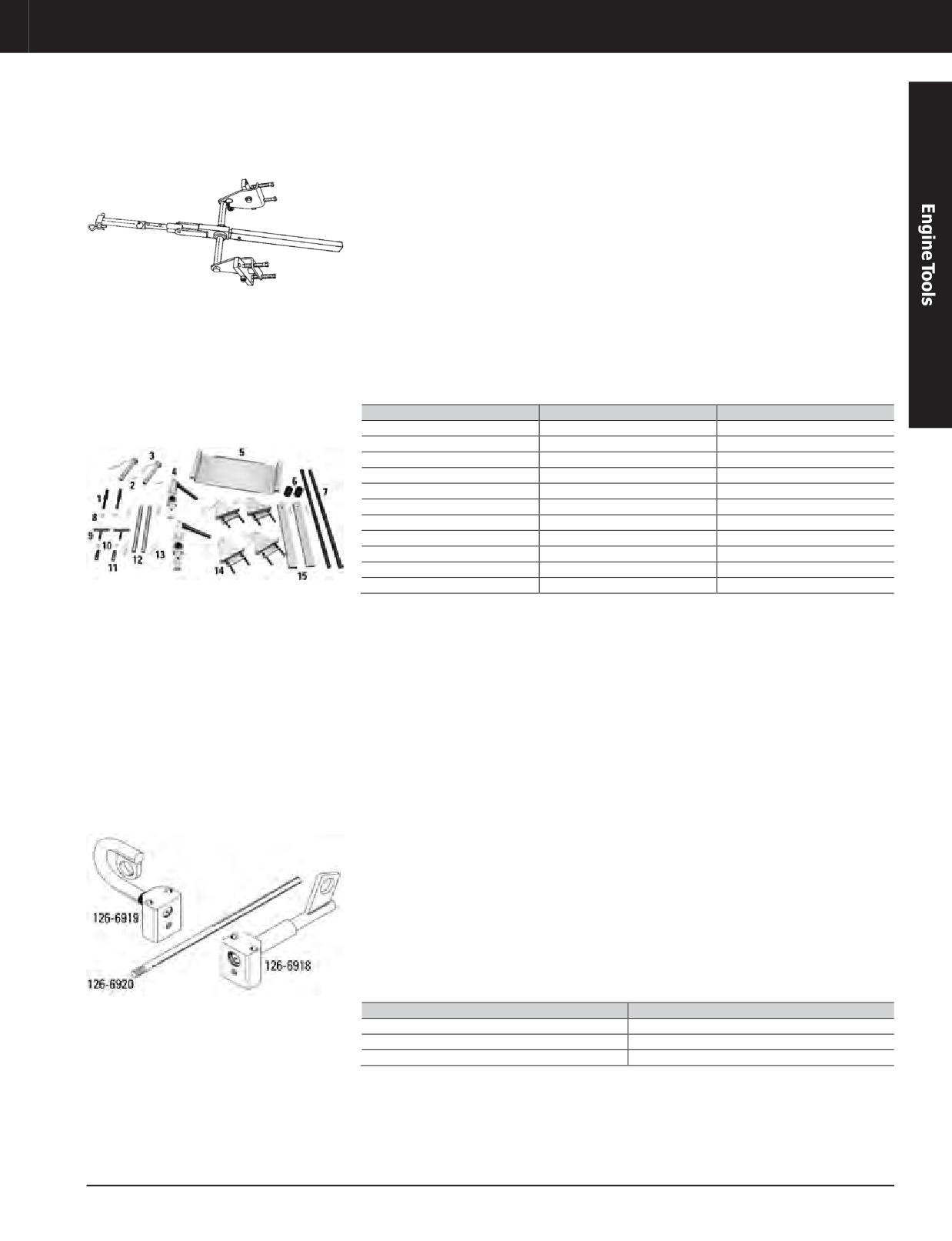
Cylinder Head, Handling Tool Group (Part of 9U-5105 Group)
Model Usage: 3600 Engines
• Used to raise and lower crankshaft main
• Most parts in the group are assembled with
bearing cap and 207-5034 Stud Tension Tool
pins and spring clips (clips prevent tooling
Group
from falling into oil pan)
• 4C-8357 Tray Support Rail is installed in oil
References
pan baffle holes and supports Stud Tensioner
• SENR3594, Service Manual Module of
Tray (tray used as work table to support main
SENR3590 Service Manual
bearing caps or stud tensioner tooling before
they are lifted into place)
• SENR3600, Service Manual Module of
SENR3595 Service Manual
• 8T-0947Tee Handle is used as handhold to
aid in alignment of 207-5034
• SENR4259, Service Manual Module of
SENR4255 Service Manual
• Two 8T-0916 Pins connect this handling group
to main bearing caps (use 4K-0367 Nuts on
pins)
Item
Part Number
Description
Assembled Handling Tool Group
—
8T-0960
Handling Tool Group
1
8T-0916
Pin
2
8T-0959
Hitch Pin
6
8T-0961
Rail Retainer Bushing
7
4C-8357
Tray Support Rail
8
4K-0367
Nut - Full
9
8T-0947
Tee Handle
10
1B-4430
Jam Nut
11
8T-0946
Tension Lift Stud
13
5P-0370
LockPin
15
-
NoLongerAvailable
a. Includes 8T-0806 Block and 9U-7238 Handle
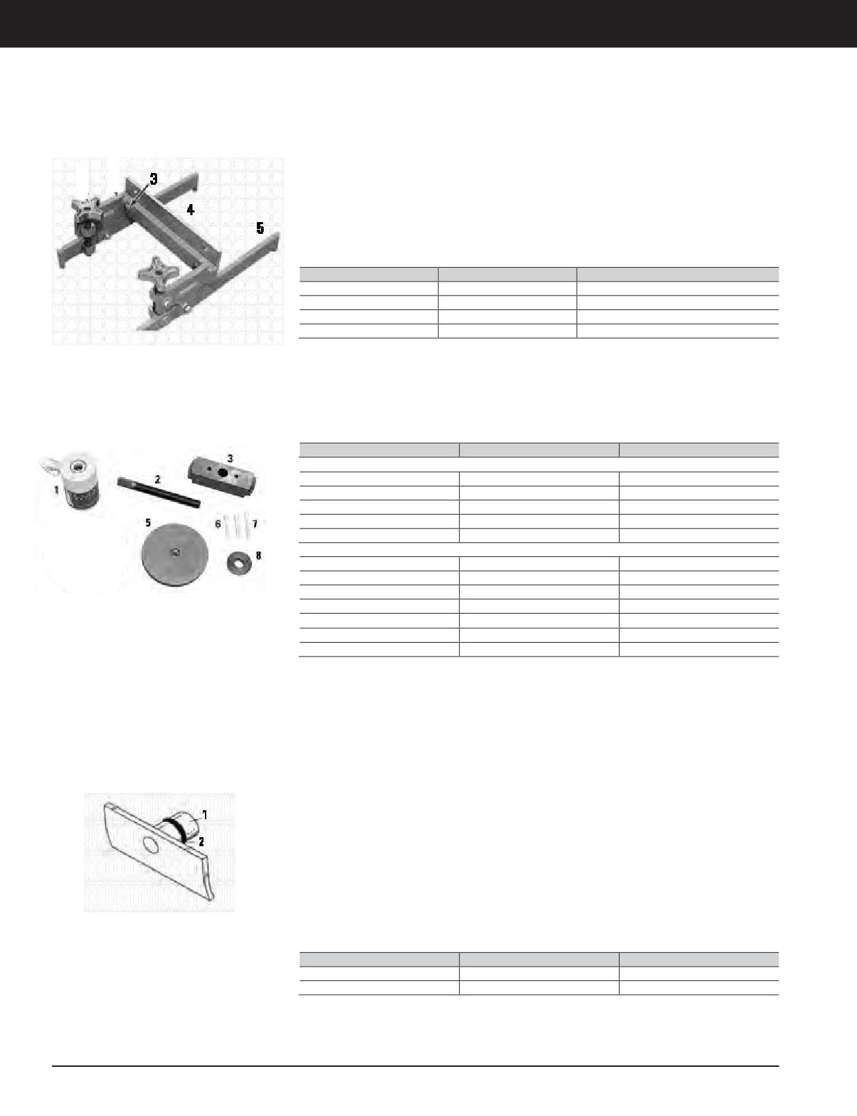
Head Lifting Bracket (3600 Vee), Head Lifting Bracket (3600 In-line), Handle Rod
(Part of 9U-5105 Group)
Model Usage: 3600 Engines
• Replaces discontinued 8T-2860 Head Lifting
• Handle rod screws into either bracket
Bracket (3600)
and helps mechanic position head during
Warranty: Caterpillar ®Six Months
assembly
• Used to remove and install heads on 3600
Engines - 126-6918 used for Vee engines
• Not shown: 5D-1972 Bolt
and 126-6920 used for in-line engines
(3/4 in -10, 11 3/4 in)
• Lifting bracket for Vee engines is designed
Specifications
with 25° angle (keeps bottom of head parallel
• Working load limit for either lifting bracket
to 25° block angle)
• 227 kg (500 lb)
• Attach lifting bracket bolt to head with two
5D-1972 Bolts (3/4 in - 10, 11 3/4 in) (part of
9U-5105 Group)
Part Number
Description
126-6918
Head Lifting Bracket
126-6919
Head Lifting Bracket
126-6920
Handle Rod
JULY 2018 Engine Tools
3-305
Engine Tools
3600 ENGINE TOOLS
Crankshaft and Camshaft, Camshaft Segment Support Group (Part of 9U-5105 Group)
Model Usage: 3600 Engines
• Used to support camshaft segments during
References
removal and installation (weight of camshaft
• SENR3594, Service Manual Manual Module
segments 28 kg [62 lb])
of SENR3590 Service Manual
• Swivel assembly is adjustable for easier
• SENR3600, Service Manual Module of
alignment of segment during installation
SENR3595 Service Manual
• SENR4259, Service Manual Module of
SENR4255 Service Manual
Item
Part Number
Description
—
8T-3029
Camshaft Segment Support Group
4
1U-6311
Camshaft Support Adapter
3
-
3/8 in - 16 Bolt (not part of 8T-3029 )
5
8T-3048
Lifting Bar
Camshaft Bearing Tools
Item
Part Number
Description
8T-0970 Camshaft Bearing Tool Group,3600 Engines
1 a
316-1496
Cylinder
2 a
184-5397
Threaded Rod
6
0L-1143
Bolt
7 a
0S-1619
Bolt
8 a
8T-0973
Insert for Cylinder
156-7155 Camshaft Bearing Tool Group, 3618 Engines
1 a
316-1496
Cylinder
2 a
184-5397
Threaded Rod
5
156-7156
Plate
6
0L-1143
Bolt
7 a
0S-1619
Bolt
8 a
8T-0973
Insert for Cylinder
9 Not Shown
317-7104
Insert for 316-1496 Cylinder
a. Common to both groups
Main Bearing Driver (Part of 9U-5105 Group)
Model Usage: 3600 Engines
• Removes/installs crankshaft main bearings
References
(old 6I-4528 Main Bearing and new 111-3378
• SENR3594, Module of SENR3590
Main Bearing) without removing crankshaft
• SENR3600, Module of SENR3595
• Bearings are easily removed by inserting tool
• SENR4259, Module of SENR4245
into crankshaft journal lubrication hole and
• SENR5535, Module of SENR5500
rotating crankshaft clockwise to roll out
Specifications
• Will also roll in new bearings by rotating
• Blade width: 90 mm (3.54 in)
crankshaft in a counterclockwise direction
• Blade thickness: 6.35 mm (0.250 in)
• Pin diameter: 19.48 mm (0.767 in)
• Threaded hole in pin allows easy removal
• Threaded puller hole in pin 8 -32
from oil passage if tool shears (tool designed
to shear to prevent damage to crankshaft)
Item
Part Number
Description
1
134-0932
Main Bearing Driver
2
8F-3469
Seal
3-306 JULY 2018 Engine Tools
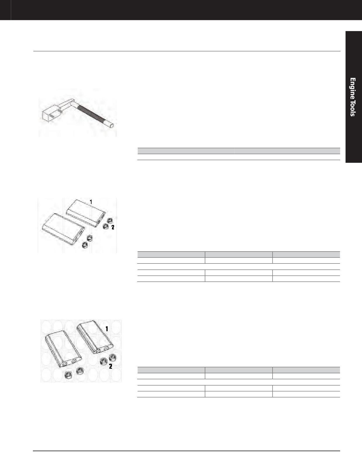
Engine Tools
3600 ENGINE TOOLS
Piston and Connecting Rod Assembly
Piston Support Group, (Part of 9U-5105)
Model Usage: All 3600 Engines
• Used to safely support piston and connecting
References
rod assembly on all 3600 Engines when
• SENR3594, Service Manual Module of
replacing connecting rod bearing
SENR3590 Service Manual
• Mounted in place of oil cooling jet with two
• SENR3600, Service Manual Module of
0S-1619 Bolts (after engine rotated until
SENR3595 Service Manual
piston at top dead center position)
Specifications
• Lightweight aluminum for ease of installation
• Support capacity: 102 kg (225 lb)
• Knurled for firm grip
• Notshown: 0S-1619Bolts, 3/8-16 x3 inch (2)
Part Number
Description
145-5190
Piston Support Group
Rod Guide Group (Part of 9U-5105 Group)
Model Usage: 3606 and 3608 Engines
• Used to protect crankshaft bearing journal
• Guide dimensions: 163 x 109 x 32 mm
from damage
(6.4 x 4.3 x 1.2 in)
• Guides help align connecting rod onto
• Knurled nut: 3/4 - 16 thread
crankshaft during installation (held to
References
connecting rod studs with 8T-2859 Nut)
• SENR3600, Service Manual Module of
• Both parts constructed from aluminum to
SENR3595 Service Manual
help prevent scratching of finished machined
surfaces
• SENR4259, Service Manual Module of
SENR4255 Service Manual
Item
Part Number
Description
—
8T-3022
Rod Guide Group
Rod Guide Group Consists of:
1
-
Guide (not serviced separately)
2
8T-2859
Nut
Guide Group (Part of 9U-5105 Group)
Model Usage: 3612 and 3616 Engines
• Used to protect crankshaft bearing journal
• Guide dimensions: 163 x 96.5 x 30.5 mm
from damage
(6.4 x 3.8 x 1.2 in)
• Guides help align connecting rod onto
• Knurled nut: 3/4 - 16 thread
crankshaft during installation (held to
Reference
connecting rod studs with 8T-2859 Nut)
• SENR3594, Service Manual Module of
• Both parts constructed from aluminum to
SENR3590 Service Manual
help prevent scratching of finished machined
surfaces
Item
Part Number
Description
—
4C-6357
Guide Group
Guide Group Consists of:
1
-
Guide (not serviced separately)
2
8T-2859
Nut
JULY 2018 Engine Tools
3-307
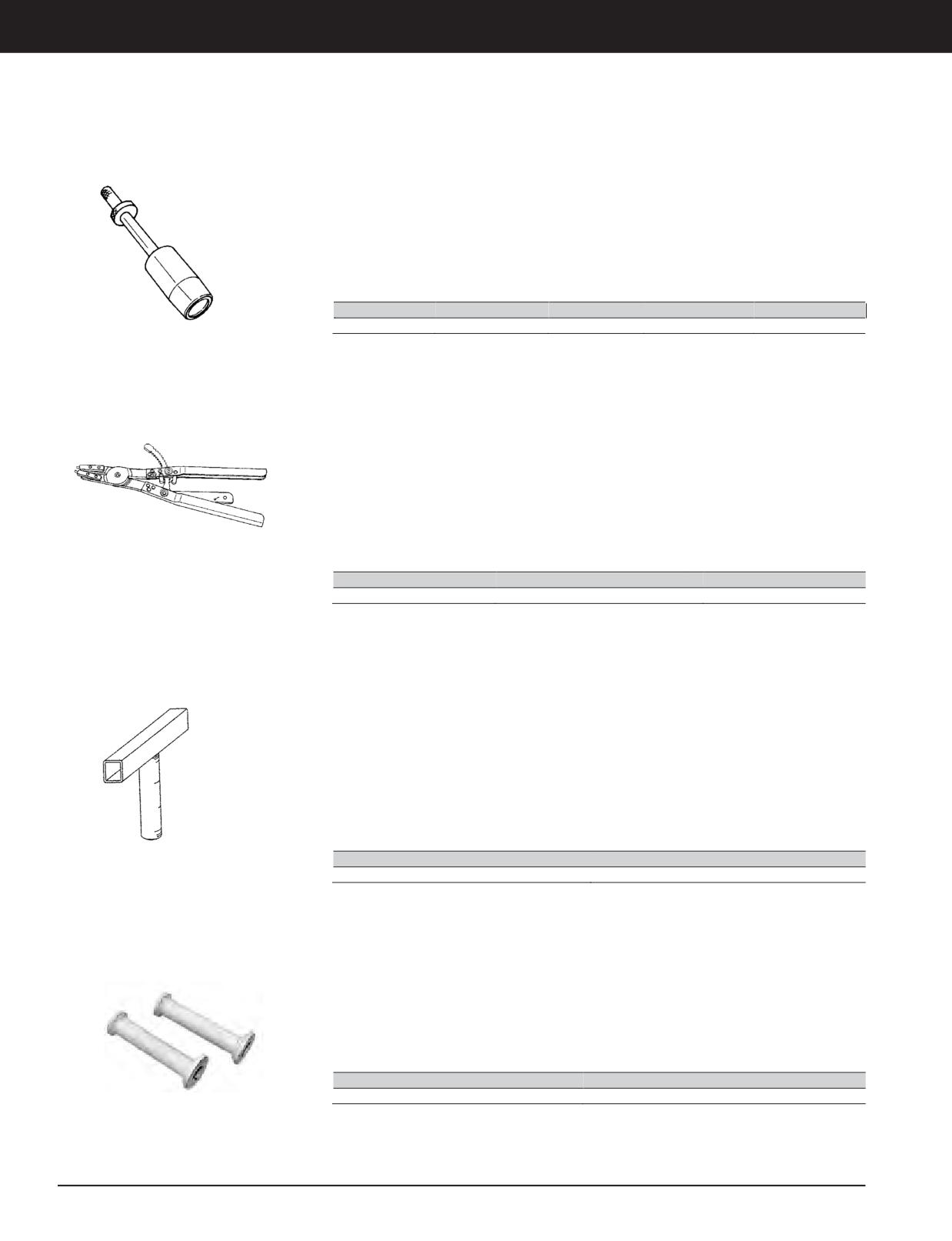
Engine Tools
3600 ENGINE TOOLS
Guide, Piston Pin (Part of 9U-5105 Group)
Model Usage: 3600
• Engines Used to easily install piston pin into
• SENR3600, Service Manual Module of
piston and rod assembly (pin is put onto guide
SENR3595 Service Manual
which helps align piston and rod bores)
• SENR4259, Service Manual Module of
• Constructed of lightweight aluminum
SENR4255 Service Manual
References
• SENR3594, Service Manual Module of
SENR3590 Service Manual
Part Number
Description
Diameter
Length
Weight
1U-8692
Piston Pin Guide
22.8 cm (9.0 in)
64.2 cm (25.3in)
7 kg (14 lb)
Internal Pliers Assembly (Part of 9U-5105 Group)
Model Usage: 3600 Engines
• Used to remove and install piston pin retainer
References
or snap ring (pliers have locking handles for
• SENR3594, Service Manual Module of
easier installation)
SENR3590 Service Manual
• Use with 9U-5981 Snap Ring Retainer to
• SENR3600, Service Manual Module of
provide added protection if snap ring slips off
SENR3595 Service Manual
pliers
•
SENR4259, Service Manual Module of
• Replaceable tip makes pliers more economical
SENR4255 Service Manual
• Service Part: 1U-6728 Tip Set
Part Number
Description
Length
136-1452
Internal Pliers Assembly
40 cm (16 in)
Snap Ring Retainer (Part of 9U-5105 Group)
Model Usage: 3600 Engines
• Used to contain piston pin retainer (snap ring)
• SENR3600, Service Manual Module of
SENR3595 Service Manual
• Used with 136-1452 Internal Pliers Assembly
during disassembly and assembly of piston
• SENR4259, Service Manual Module of
and connecting rod
SENR4255 Service Manual
References
Specifications
• SENR3594, Service Manual Module of
• Handle: 31.8 mm (1.25 in) square tubing
SENR3590 Service Manual
• Body diameter: 42.9 mm (1.68 in)
• Body length: 20 x 20 cm (7.8 x 7.8 in)
Part Number
Description
9U-5981
Snap Ring Retainer
Cylinder Liner Spacer Assembly (Part of 9U-5105 Group)
Model Usage: 3600 Engines
• Used to install cylinder liner into block (using
Specifications
two will easily and evenly seat the liners)
• Length: 31.432 cm (12.375 in)
• Steel tube designed to fit over head studs
• 2 required
• Used with 2 head-stud nuts, 4C-6987 Socket
(184-3131 Socket for 3618 Engines) and
239-6826 Ratchet (1/2 inch Drive)
Part Number
Description
191-1135
Cylinder SpaceAssembly
3-308 JULY 2018 Engine Tools
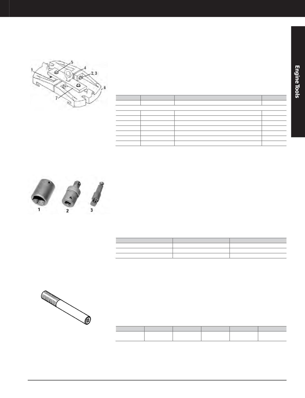
Engine Tools
3600 ENGINE TOOLS
Block, Cylinder Installation Tool Group (Part of 9U-5105 Group)
Model Usage: 3600 Engines
• Used to remove and install cylinder assembly,
References
cylinder liner, and piston and connecting rod
• SENR3594, Service Manual Module of
assembly (provides convenient method of
SENR3590 Service Manual
attaching a hoist)
SENR3600, Service Manual Module of
•
• Piston and connecting rod assembly can be
SENR3595 Service Manual
removed separately using 235-0612 Bracket,
• SENR4259, Service Manual Module of
9S-1366 Bolt, and 5P-1076 Washer
SENR4255 Service Manual
Item
Part Number
Description
Qty.
—
235-0632
Cylinder Installation Tool Group
-
Cylinder Installation Tool Group Consists of:
1
1F-7958
Full Nut (1/2 - 13) (fork mounting hardware)
2
2
9S-1366
Bolt (1/2-13)
2
3
5P-1076
Hard Washer, 13.5 mm ID x 30 mm OD
6
4
1U-7619
Spacer
2
5
0V-0375
Bolt
2
6
4C-9040
Bracket
2
7
235-0612
Bracket Assembly
1
Shank-Hex (Part of 9U-5105 Group), Universal Joint (Part of 9U-5105 Group)
Model Usage: 3600 Engines
• Used to easily rotate crankshaft
• 4C-9819 Universal Joint:
- Outside diameter: 30 mm (1.9 in)
• Used with 213-3110 Socket, or similar part,
- Overall length: 63 mm (2.5 in)
and 12.7 mm (1/2 in) drill (reversible variable
- Male drive end: 1/2 in square drive with
speed drill works best, but is not necessary)
lock button
Specifications
- Female drive end: 1/2 in square drive
- 4C-9818 Hex Shank:
- Shank size: 7/16 hex
- Shank length: 32 mm (1.3 in)
- Drive end: 1/2 in square drive with lock
button
- Overall length: 70 mm (2.8 in)
Item
Part Number
Description
1
213-3110
Socket, 1 1/8 in
2
4C-9819
Universal Joint
3
4C-9818
Hex Shank
Vibration Damper and Flywheel, Damper Guide Pin (Part of 9U-5105 Group)
Model Usage: 3600 Engines
• Used to align and support vibration damper
References
during assembly and disassembly of 3606,
• SENR3594, Service Manual Module of
3608, and 3612 Engines (2 required)
SENR3590 Service Manual
• 1/2 inch square drive socket for easy
• SENR3600, Service Manual Module of
installation and removal
SENR3595 Service Manual
• SENR4259, Service Manual Module of
SENR4255 Service Manual
Part No.
Description
Diameter
Length
Thread
Weight
DamperGuide
4C-9426
25 mm (1 in)
15.2 cm (6.0 in)
1 - 14 thd
0.6 kg (1.3)
Pin
JULY 2018 Engine Tools
3-309
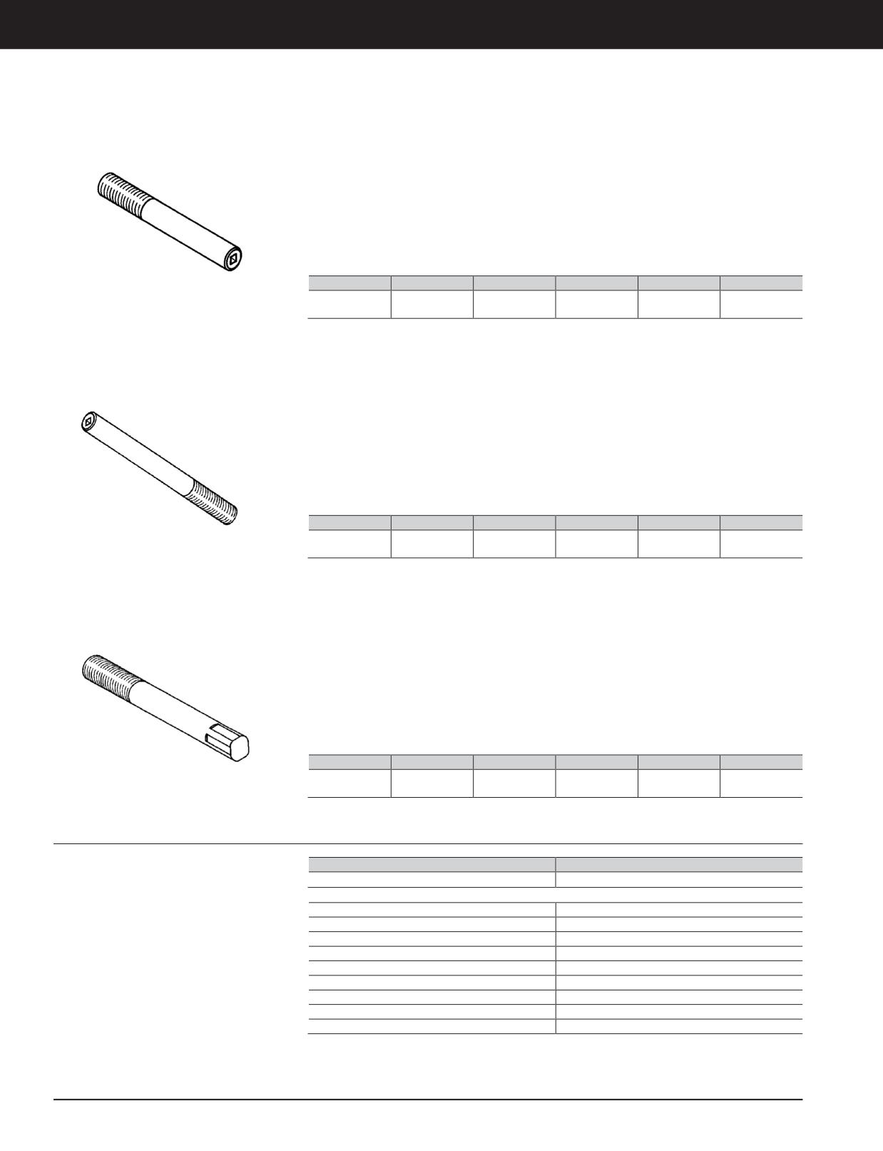
Engine Tools
3600 ENGINE TOOLS
Damper Guide Pin (Part of 9U-5105 Group)
Model Usage: 3600 Engines
• Used to align and support single vibration
References
dampers (2 required)
• SENR3594, Service Manual Module of
• 1/2 inch square drive socket for easy
SENR3590 Service Manual
installation and removal
• SENR3600, Service Manual Module of
SENR3595 Service Manual
• SENR4259, Service Manual Module of
SENR4255 Service Manual
Part No.
Description
Diameter
Length
Thread
Weight
DamperGuide
1U-9393
25 mm (1 in)
15.2 cm (6.0 in)
1 - 8thd
0.6 kg (1.3)
Pin
Damper Guide Pin (Part of 9U-5105 Group)
Model Usage: 3600 Engines
• Used to align and support outer vibration
References
damper of dual vibration dampers (2 required)
• SENR3594, Service Manual Module of
• 1/2 inch square drive socket for easy
SENR3590 Service Manual
installation and removal
• SENR3600, Service Manual Module of
SENR3595 Service Manual
• SENR4259, Service Manual Module of
SENR4255 Service Manual
Part No.
Description
Diameter
Length
Thread
Weight
DamperGuide
28.4 mm
1U-9392
25.4 cm (10.0in)
1 1/8 - 8 thd
1.3 kg (2.9)
Pin
(1.12 in)
Flywheel Guide Pin (Part of 9U-5105 Group)
Model Usage: 3600 Engines
• Used to align and support flywheel and rear
References
gear support assembly during installation and
• SENR3594, Service Manual Module of
removal (2 required)
SENR3590 Service Manual
• 1/2 inch external square drive for easy
• SENR3600, Service Manual Module of
installation and removal
SENR3595 Service Manual
• SENR4259, Service Manual Module of
SENR4255 Service Manual
Part No.
Description
Diameter
Length
Thread
Weight
Flywheel Guide
28.4 mm
8T-0914
61 cm (24 in)
1 1/8 - 12 thd
3kg (6lb)
Pin
(1.12 in)
Diesel Tool Group (9U-5106)
Model Usage: 3600 Diesel Engines
Part Number
Description
9U-5106
Diesel Tool Group
Warranty: Caterpillar ®Six Months
9U-5106 Consists of:
130-6993
Injector Bore Brush
1U-8795
Governor Torque Arm
4C-5719
Piston Ring Compression Group
4C-6594
Timing Tool Group
5P-0328
Crowfoot Wrench, 7/8 in (Fuel Line)
5P-0329
Crowfoot Wrench, 15/16 in (Fuel Line)
6V-7073
Liner Puller Group
8T-3268
Bolt (2)
9U-5932
Extension Camshaft Torque
3-310 JULY 2018 Engine Tools
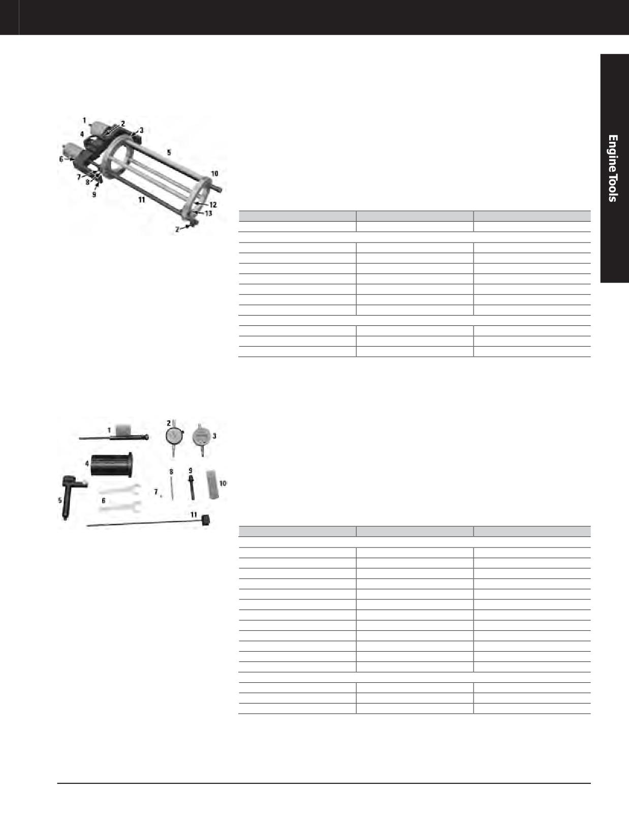
Engine Tools
3600 ENGINE TOOLS
Liner Puller Group (Part of 9U-5106 Group)
Model Usage: 3600 Diesel Engines
• Used to remove and install cylinder liner using
• Hydraulic pump connects to two hydraulic
hydraulic pressure (hoist attaches to puller to
puller assemblies for a combined pulling force
easily handle tool and cylinder liner)
of 11 tons at 5000 PSI
• Used with 350-7768 Hydraulic Pump (115 Volt)
References
or 350-7769 Hydraulic Pump (230 Volt); other
• SENR3594, Service Manual Module of
required tooling is 8T-3035 Lines Group and
SENR3590 Service Manual
8T-0820 Pressure Gauge
• SENR3600, Service Manual Module of
SENR3595 Service Manual
Item
Part Number
Description
—
6V-7073
Liner Puller Group
6V-7073 Liner Puller Group Consists of:
1
316-1493
Hydraulic Puller Group
2
2J-5245
Bolt - Hex Socket Head
5
6V-7069
Rod Spacer
8
4B-5278
Washer
11
299-5231
Leg Assembly
12
4D-3120
Bolt
13
4H-6996
Spring Pin
Not shown
-
1B-4331
Nut
—
2K-6073
Bolt
—
4B-5276
Bolt Washer
Timing and Fuel Setting Tool Group (Part of 9U-5106 Group)
Model Usage: 3600 Diesel Engines
• Replaces discontinued 6V-6170 Timing and
• 6V-3075 Dial Indicator has black numbers and
Fuel Setting Tool Group
markings for positive travel and red markings
for negative travel (369-2607 is an optional
• Used to accurately test and adjust injector
digital indicator)
synchronization and fuel timing dimension
• 4C-6593 Valve Lash Tool is used to check
References
and adjust valve lash clearance of intake and
• SENR3593, Service Manual Module of
exhaust valves using a dial indicator (used
SENR3590 Service Manual
with 6V-3075 Dial Indicator and 8S-3675
• SENR3599, Service Manual Module of
Contact Point)
SENR3595 Service Manual
• SEHS9599, Special Instruction
Item
Part Number
Description
4C-6594 Timing and Fuel Setting Tool Group Consists of:
-
4C-6594
Timing Tool Group
1
6V-9058
Fixture Assembly
2
6V-3075
Indicator - Dial
3
369-2607
Digital Indicator
4
6V-9056
Set Gauge
5
4C-6593
Adjusting As - Valve Lash
6
6V-7918
Wrench
7
8S-3675
Point - Indicator
8
5P-7263
Indicator Contact Point
9
4C-8753
Extended Collet
10
5P-7276
Container
11
6V-9057
Rack Synchronizing Gauge
Not shown
-
4C-6595
Top Insert
—
4C-6596
Bottom Insert
—
6V-7145
Case
a. Parts used to upgrade a discontinued 6V-6170 to a 4C-6594 (also order an NEEG2491 Decal)
JULY 2018 Engine Tools
3-311
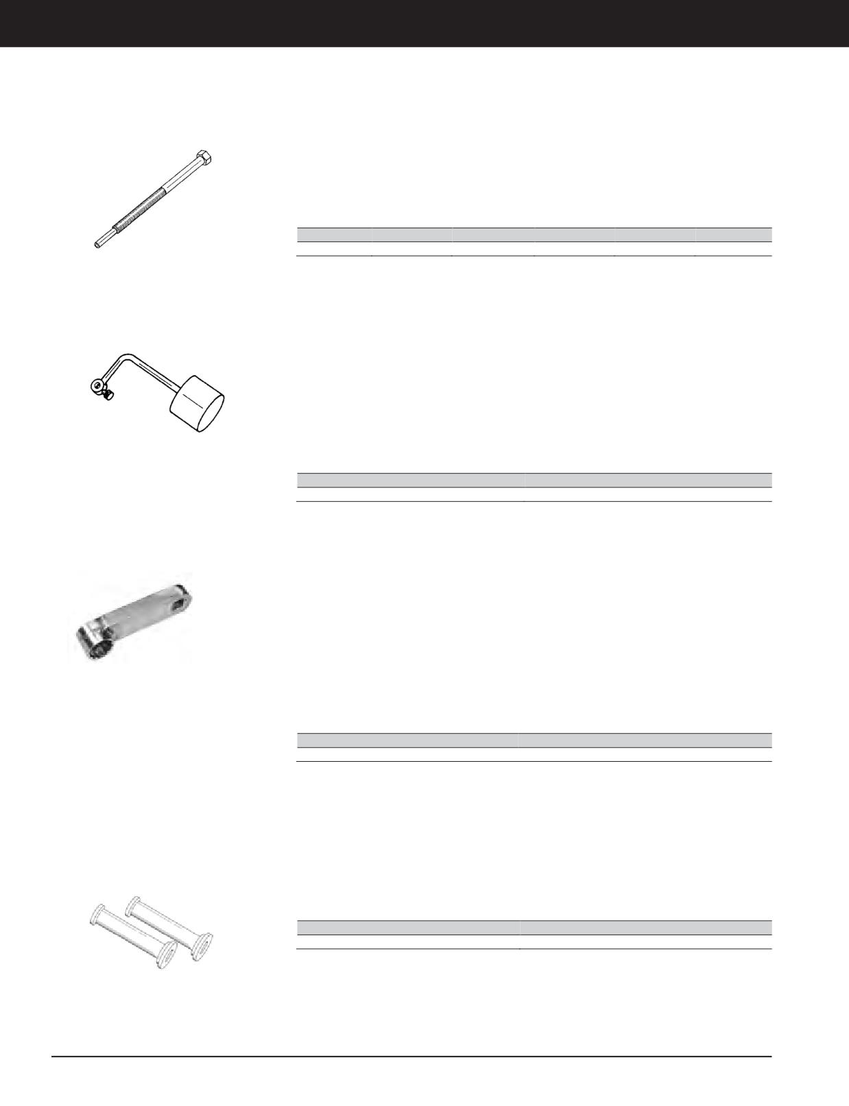
Engine Tools
3600 ENGINE TOOLS
Bolt (Part of 9U-5106 Group)
Model Usage: 3600 Engines
• Usedto remove unit injector by evenly
References
tightening two bolts at the same time
• SENR3594, Service Manual Module of
SENR3590 Service Manual
• SENR3600, Service Manual Module of
SENR3595 Service Manual
Part No.
Description
Overall Length Pilot Diameter
Pilot Length
Thread
8T-3268
Bolt
13.9 cm (5.5 in)
6 mm(0.24 in)
27 mm (1.1 in)
15/16 - 18
Governor Torque Arm (Part of 9U-5106 Group)
Model Usage: 3600 Engines
• Holds governor or actuator terminal shaft to
References
fuel “ON” position while injectors are being
• SENR3594, Service Manual Module of
adjusted
SENR3590 Service Manual
• When torque arm is installed with weight in
• SENR3600, Service Manual Module of
horizontal position, 18.6 N·m (13.65 ft-lb) is
SENR3595 Service Manual
applied to governor linkage
• Shaft clearance hole diameter: 16.3 mm
(0.64 in)
Part Number
Description
1U-8795
Governor Torque Arm
Camshaft Torque Extension (Part of 9U-5105 and 9U-5106 Groups)
Model Usage: 3600 Engines
• Used to remove and install bolts retaining
Specifications
thick-flange camshaft segments
• Square drive: 1/2 in
• Designed with minimum clearance to fit onto
• Socket (12 point): 15/16 in
the bolts (conventional sockets cannot reach
• Length of extension: 100 mm (4.0 in)
the bolts)
• Using the extension requires a calculation to
determine the correct torque; the extension
uses a 100mm (4 in)lever arm(use Form
SEHS7150 to calculate the proper torque
wrench setting)
Part Number
Description
9U-5932
Extension Camshaft Torque
Cylinder Liner Spacer Assembly
Essential Tool
• Used to install cylinder liner into cylinder head
• Using two spacer assemblies will easily and
evenly seat cylinder liners
Model Usage: All 3600 and G3600 Engines
• Used with 4C-6987 Socket and two cylinder
head stud nuts
• Overall length: 314.32 mm (12.375 in)
Warranty: Caterpillar ®Six Months
• Used with 184-3131 Socket for 3618 Engines
• Steel tube fits over cylinder head studs
Part Number
Description
191-1135
Cylinder SpaceAssembly
3-312 JULY 2018 Engine Tools
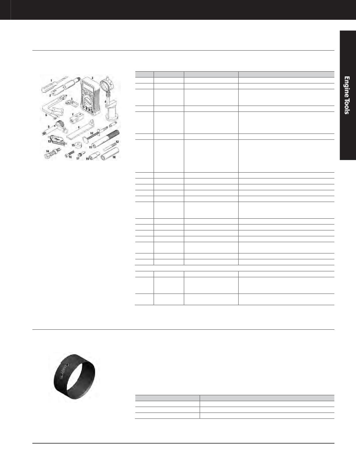
Engine Tools
3600 ENGINE TOOLS
MaintenanceTool Group (Continued)
Model Usage: G3600 Engines
• Used to perform routine maintenance tasks on
G3600 Engines
Warranty: Caterpillar ®Six Months
Item
Part Number
Description
Use
—
146-2726
Maintenance Tool Group
-
1
6V-9124
Screwdriver
Used for terminal strips
Connects outside air pressure source to
2
146-2739
Cylinder Pressure Adapter
cylinders on 3500 and 3600 Engines during
cylinder leak down testing
3
257-9140
Fluke 87V Multimeter
Test and adjust electrical circuits
Measures valve seat recession by placing
magneticblockon topof valve rotator with rod
4
148-2997
Valve Recession Tool Kit
extending to top of cylinder head (used with 6V-
3075 Dial Indicator or 369-2607 Digital Indicator)
5
439-3938
Bracket Assembly - Link
Turbo lift bracket
Set gas admission valve (GAV) lash by
installing in valve cover base rear bolt hole and
adjusting 5P-2056 Indicator Tip on gas admission
6
146-2742
GAV Lash Tool
rocker arm flat (use with 147-5536 Indicator
Contact Point and 6V-3075 Indicator on gas
admission rocker arms with pin)
7
143-8995
Leak Down Check Tool
Tests check valves in prechamber
8
9U-6244
Support
Turbo support
9
4C-6593
Adjusting As - Valve Lash
Checkandadjustvalvelash
10
146-2728
Flex Pickup Tool
Remove check valve seal
11
1P-0529
Handle
Waste gate tool
Install equally spaced bolts in outer ring of
12
9U-6248
Guide Bolt
holes in back of turbocharger compressor
housing during assembly
13
9U-7516
Spark Plug Gauge
Check spark plug gap
14
9U-7511
Spark Plug Seat Cleaner
Spark plug seat cleaner
15
1P-0462
Plate, 0.937 in Diameter
Waste gate tool
16
6L-5897
Bolt, 7/8 in long
Waste gate tool
Checksleak down fixture(143-8995) before
17
143-8997
Dummy Check Valve
testing check valves
18
4C-4601
Spark Plug Socket
Remove and install spark plugs
19
9S-5031
Deep Well Socket
Removes combustion sensor spark plug
Not shown
-
285-0901
Blowby Pickup Group
Check blow by volume
Measures volume of blowby gas coming from
-
368-9910
Multi-toolGroup
crankcase breather and air velocity through
radiator
Software LicenseCard (required to activate
-
-
NETG5044
software)
a. Comes with insert for removing spark plugs
Crankshaft Journal Cover
Model Usage: 3600/C280
• Used to protect crankshaft bearing journals
• 443-4073 is used to protect connecting rod
from impact damage
journals on 12 and 16 cylinder engines.
Warranty: Manufacturer’s
One cover will protect half of the journal in
• 443-4070 is used to protect main bearing
case one rod is removed. If both rods are
journals. One cover will protect the complete
removed, use two covers for complete journal
journal.
protection.
• 443-4072 is used to protect connecting rod
journals on 6 and 8 cylinder engines. One
cover will protect the complete journal.
Part Number
Dimensions
443-4070
876 mm long x 120 mm wide 34.5 in long x 4.7 in wide
443-4072
762 mm long x 110 mm wide 30.0 in long x 4.3 in wide
443-4073
762 mm long x 97 mm wide 30.0 in long x 3.8 in wide
JULY 2018 Engine Tools
3-313
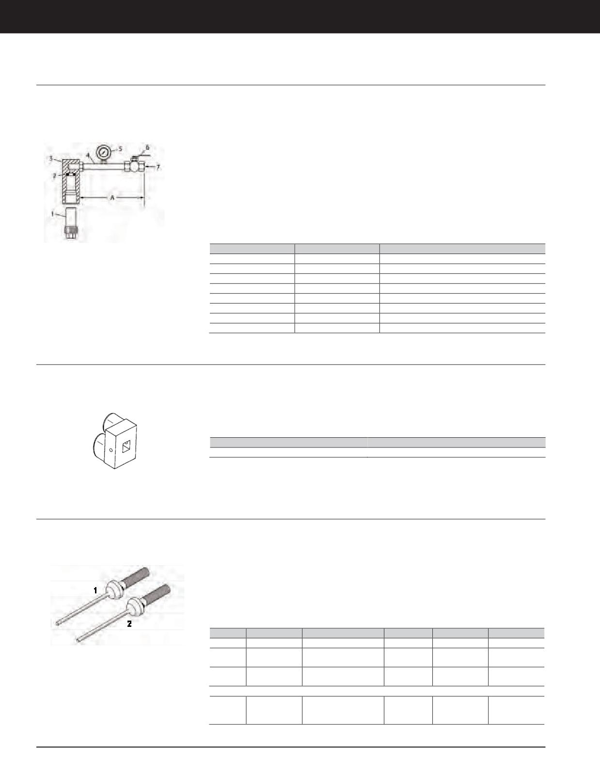
Engine Tools
3600 ENGINE TOOLS
Leak Down Check Tool, Check Valve (Dummy)
Model Usage: G3606, G3608, G3612, and G3616
• Used to test prechamber check valves for
• A 2M-4453 O-ring Seal is included with leak
Engines
leakage
downcheck tool and is a service part
Warranty: Caterpillar ®Six Months
• When 827kPa(120 PSI) air pressure is
• When connecting air supply, it must be as
applied, pressure cannot leak down below
close as possible [within 300.0 mm (12.0 in)
689 kPa (100 PSI) within five seconds
max] to inlet side of air pressure gauge
• Used with external compressed air supply,
• Maximum air pressure (pressure gauge): 1378
air pressure gauge with a maximum 1378 kPa
kPa (200 PSI)
(200 PSI) capacity, and quick action shut-off
• Maximum length between tool and leak down
valve
check valve: 304.0 mm (12.0 in)
• 143-8997 Dummy Check Valve is used to
verify that leak down check tool does not have
any leaks
Item
Part Number
Description
1
143-8997
Dummy Check Valve
2
2M-4453
O-ring Seal
3
143-8995
Leak Down Check Tool
4
-
Tube
5
-
Pressure gauge
6
-
Ball valve
7
-
Air supply
A
-
305 mm (12.0 in) maximum length
Governor Calibration Tool
Model Usage: 3600 Locomotive Engine with
• Holds the governor shaft to the fuel on
• Has 2 dowels on one side to fit into 2 holes on
PGEV Governor
position when synchronizing injectors
governor shaft position indicator
Warranty: Caterpillar ®Six Months
• Makes it easier to rotate governor terminal
• 1/2 inch square drive connection on other side
shaft and easier to hold it in position when
for attaching socket wrench as lever arm
adjusting power setting
Part Number
Description
4C-6583
Governor Calibration Tool
Diesel Valve Seat Group
Model Usage: 3600 Diesel Engines
• Used to measure valve seat angle after
• Lightly oiling tool before storage is
machining of seat
recommended to prevent corrosion of
Warranty: Caterpillar ®Six Months
precision machined surfaces
• Pilots in valve guide to ensure that seat is
perpendicular to guide
• Tool group includes case and foam insert
• Features knurled handle for positive grip
References
• SEBF8129, Guideline for Reusable Parts
• SEHS0095, Special Instruction
Item
Part No.
Description
Seat Angle
Overall Length
Pilot Diameter
—
147-2285
Diesel Valve Seat Group
-
-
-
344.50 mm
1
147-1642
Valve Seat Angle Gauge
30.5°
16mm(0.630in)
(13.56 in)
344.50 mm
2
147-1643
Valve Seat Angle Gauge
31°
16mm(0.630in)
(13.56 in)
Not Shown
Case— Plastic,
-
6V-3072
NEEG2574 Group Decal
-
-
-
on lid
3-314 JULY 2018 Engine Tools
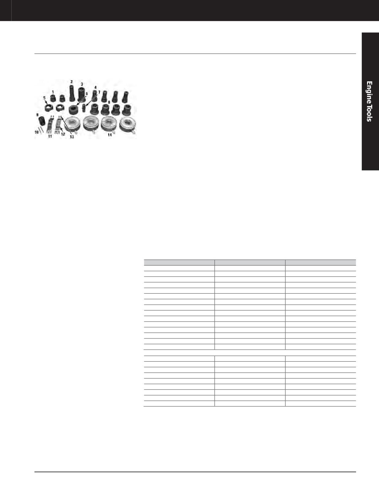
Engine Tools
3600 ENGINE TOOLS
Stud Tensioner Tool Group
Model Usage: 3600 Engines
• Used to tension cylinder head studs and main
• 9U-5141 Nut Turning Handle used to loosen
bearing studs
and tighten nuts while studs are extended
Warranty: Caterpillar ®Six Months
(9U-5141 Nut Turning Handle replaces
• Used with 8T-0820 Pressure Group and
discontinued 4C-6986 Nut Turning Handle)
8T-3035 Lines Group
• 4C-6987 Socket used to pre-torque cylinder
• Used with one of these pumps: 350-7768
head nuts
Hydraulic Pump (115 Volt) or 350-7769
Hydraulic Pump (230V); 8T-0820 Pressure
References
Gauge and 8T-3035 Lines Group also required
• SENR3594, Service Manual Module of
(Cannot be used with 156-7166, 227-6724,
SENR3590 Service Manual
227-8834, 191-5347, and 156-7167 Hydraulic
Pumps which are used with the other stud
• SENR3600, Service Manual Module of
tensioning tools)
SENR3595 Service Manual
• Used with 8T-0960 Handling Tool Group to
• SENR4259, Service Manual Module of
remove and install main bearings
SENR4255 Service Manual
• Simultaneously tension four cylinder head
• SEHS9342, Special Instruction
studs or two crankshaft main bearing studs
Specifications
(use 8T-0960 Handling Tool Group when
removing crankshaft main bearings)
• 8T-0895 Cylinder Group:
- Applied force of each cylinder at maximum
• 4C-5816 Retainer Collar attaches as
pressure : 1540 N@ 69,000 kPa (173 ton@
protective device to 8T-0895 Cylinder Group
10,000 PSI)
before tightening or loosening crankshaft
- Piston area: 223 cm² (34.6 sq in)
main bearing studs (helps contain 207-4607
- Weight: 20 kg (45.0 lb)
Collar and stud in case of breakage)
• 8T-0493 Cylinder Test Stud, 8T-0495 Test Stud
Spacer, and two 207-4607 Thread Collars are
used to test 8T-0895 Cylinder Group
Item
Part Number
Description
—
207-5034
Stud Tensioner Tool Group
1
207-4607
Threaded Collar (bearing stud)
2
8T-0889
Threaded Collar (head stud)
3
8T-0898
Cylinder Head Pedestal
4
8T-0891
Threaded Collar (head stud)
5
8T-0896
Bearing Pedestal
6
8T-0494
Test Stud Spacer
7
8T-0493
Cylinder Test Stud
8
8T-0897
Cylinder Head Pedestal
9
4C-6987
Socket
10
9U-5141
Nut Turning Handle
11
1B-0581
Bolt
12
4C-5816
Collar Retainer
13
0L-1351
Bolt
14
8T-0895
Cylinder Group
Not shown
-
8T-0901
Valve
—
8T-0902
Screw
—
8T-0903
Screen
—
8T-0904
Ring
—
8T-0907
Spring
—
8T-0908
Bolt
—
8T-0909
Wiper
—
8T-0915
Ring
—
8T-0917
Ring
JULY 2018 Engine Tools
3-315
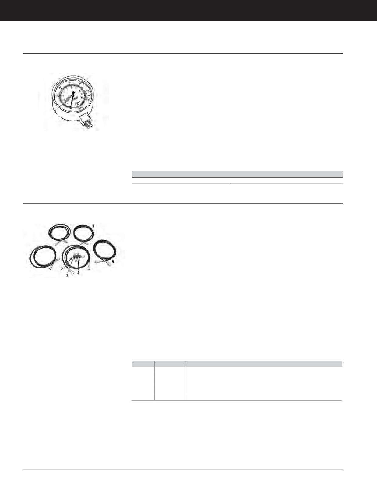
Engine Tools
3600 ENGINE TOOLS
Pressure Gauge
Model Usage: 3600 Engines
• Used to provide pressure reading of hydraulic
• SENR3600, Service Manual Module of
pumps when used with 207-5034 Stud
SENR3595 Service Manual
Tensioner Group or 8T-0970 Cam Bearing
• SENR4259, Service Manual Module of
Tool Group or 6V-7073 Liner Puller Group or
SENR4255 Service Manual
4C-8568 Liner Puller Group
Specifications
• Used with 350-7768 Hydraulic Pump (115 Volt)
or 350-7769 Hydraulic Pump (230 Volt);
• Pressure range: 0 - 70,000 kPa
2N-1931 Fitting, 45° Street Ell can be used to
(0 - 10,000 PSI)
make gauge face more visible
• Operating temperature: -20° to 65°C
• Liquid-filled gauge has face calibrated with
(-4° to 150°F)
both kPa and PSI
• Male-threaded connection: 1/4 - 18 NPTF
References
• Gauge diameter: 102 mm (4.0 in)
• SENR3594, Service Manual Module of
SENR3590 Service Manual
Part Number
Description
8T-0820
Standard PressureGauge
Lines Group
Model Usage: 3600 Engines
• Used to connect hydraulically operated tool to
Specifications
hydraulic pump - 350-7768 Hydraulic Pump
• 6D-7726 Hose Assembly:
(115 Volt) or 350-7769 Hydraulic Pump (230V);
- Length: 3480 mm (137.0 in)
used in the following applications: remove
- Maximum pressure rating: 70,000 kPa
and install cylinder head and crankshaft main
(10,000 PSI)
bearings, camshaft bearings, and cylinder
- Threaded connections (both ends):
liners
1/4 - 18 NPTF
• Used with 207-5034 Stud Tensioner Tool
• 1P-2375 Coupler Assembly (male):
Group, 6V-7073 Liner Puller Group, 8T-0970
- Threaded connection: 3/8 - 18 NPTF
Camshaft Bearing Tool Group, 6V-7073 Liner
- Proof pressure: 82,000 kPa (12,000 PSI)
Puller Group or 4C-8568 Liner Puller Group
- Burst pressure: 137,000 kPa (20,000 PSI)
References
• 1P-2376 Coupler Assembly (female):
- Threaded connection: 1/4 - 18 NPTF
• SENR3594, Service Manual Module of
- Proof pressure: 82,000 kPa (12,000 PSI)
SENR3590 Service Manual
- Burst pressure: 144,000 kPa (21,000 PSI)
• SENR3600, Service Manual Module of
• 8T-5206 Manifold:
SENR3595 Service Manual
- Number of ports: 6
• SENR4259, Service Manual Module of
- Threaded connection (female):
SENR4255 Service Manual
3/8 - 16 NPTF
- Plug ( 3/8-18 NPTF): 3J-5390 Plug
Item
Part Number
Description
—
8T-3035
Lines Group
1
6D-7726
Hydraulic Hose (2)
2
3J-5390
Plug - NPTF (Ext Hex) 3/8 in-18 NPTF external to 1/8 in-27 NPTF internal
3
8T-5206
Manifold
4
1P-2375
Coupler Assembly Quick Connective (Male)
5
1P-2376
Coupler Assembly Quick Connective (Female) (2)
3-316 JULY 2018 Engine Tools
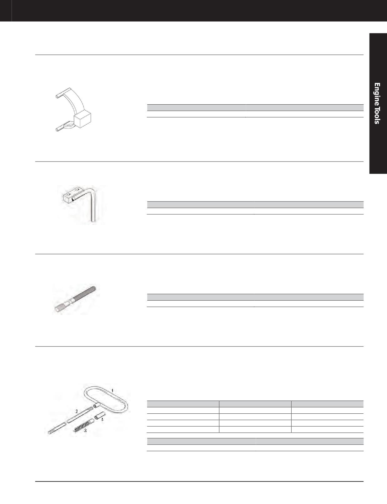
Engine Tools
3600 ENGINE TOOLS
Camshaft Separation Assembly
Model Usage: 3618 Engines (serial numbers
• Used to separate camshaft segments
• Bolt length: 57.2 mm (2.25 in)
2MW1-UP)
• Replaces separating method which used
• Bolt size: 5/8 - 11
Warranty: Caterpillar ®Six Months
jacking screws (these holes are no longer
Reference
available in current camshafts)
• RENR1333-01, Service Manual
• Used with 9X-8881 Bolt
Part Number
Description
156-7159
Camshaft Separation Assembly
Piston Support
Model Usage: 3618 Engines
• Used to safely support piston and connecting
• Made of lightweight aluminum for easy
rod assembly while replacing connecting rod
installation
Warranty: Caterpillar ®Six Months
bearings
• Mounts in place of cooling jet with existing
bolts
Part Number
Description
156-7160
Piston Support
Rod Cap Guide (3618)
Model Usage: 3618 Engines (2MW1-Up)
• Used to easily remove and install connecting
• Helps prevent damage to connecting rod cap
rod cap
Warranty: Caterpillar ®Six Months
• Thread: M24 x 3.0
• Guides (2) thread into lower portion of
connecting rod
Part Number
Description
178-5063
Rod Cap Guide
Cleaning Kit
ModelUsage: 3600 GasEngines with Two-Stage
• Used to clean water tubes in 2-stage after
• Kit includes 9.5 mm (0.38 in) diameter
After Coolers
coolers
brushes, rods, handle, and connector
Warranty: Caterpillar ®Six Months
• Soft deposits left by coolant are removed by
• Rotate cleaning rods and brushes in clockwise
inserting brushes into after cooler tubes and
direction to prevent parts from unscrewing
working back and forth through the length of
coolant tubes
Item
Description
Quantity
1
Handle
1
2
Rod
3
3
Brush
12
4
Connector
2
Part Number
Description
145-0316
Cleaning Kit
JULY 2018 Engine Tools
3-317
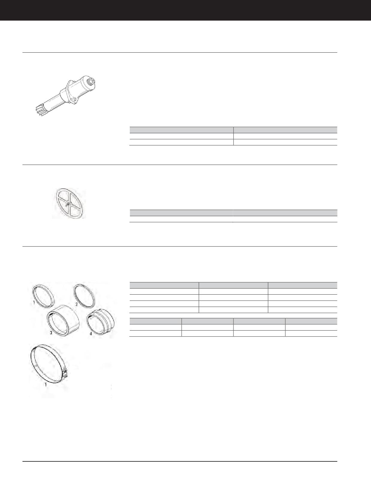
Engine Tools
3600 ENGINE TOOLS
Prechamber Machining Tool Group (G3600)
Model Usage: All G3600 Engines
• Used to remove pitting and corrosion in lower
NOTICE
sealing surface of prechambers
Warranty: Caterpillar ®Six Months
Use with caution and as a last resort to salvage
• Machines lower sealing surface of
cylinder heads. Excessive material removal could
prechamber
result in loss of core credit of the cylinder head.
Follow step-by-step directions in NEHS0790 Tool
• Maximum material removal: 0.5 mm (0.02 in)
Operating Manual provided with this tool.
Reference
• NEHS0790, Using the 187-6273 Prechamber
Machining Tool Group (G3600)
Part Number
Description
187-6273
Prechamber Machining Tool Group
460-1375
Adjustable Ring
Template Seal
Model Usage: 3600 and G3600 Engines
• Just outline ID and OD of template to reveal
• Any nicks, gouges, and/or damage in this area
sealing surface
may result in incorrect sealing
Warranty: Caterpillar ®Six Months
• Used to easily and quickly identify area of
cylinder head that needs a smooth sealing
surface
Part Number
Description
151-8689
Template Seal
Seal Installer Group
Model Usage: 3600 Diesel and Heavy Fuel Oil
• Used to install seals on high pressure
• Group contains seal compressors and pliers
Engines
aftercoolers (HPAC)
to consecutively install both seals— makes
installation easier and faster, while helping to
Warranty: Caterpillar ®Six Months
eliminate seal damage during installation
Item
Part Number
Description
1
148-6442
Ring
2
148-6443
Ring Insert
3
148-6444
Seal Driver
4
148-6445
Seal Installer
Item
Part Number
Description
Qty.
—
148-9704
Seal Installer Group
-
1
148-9705
Seal Ring Compressor
2
3-318 JULY 2018 Engine Tools
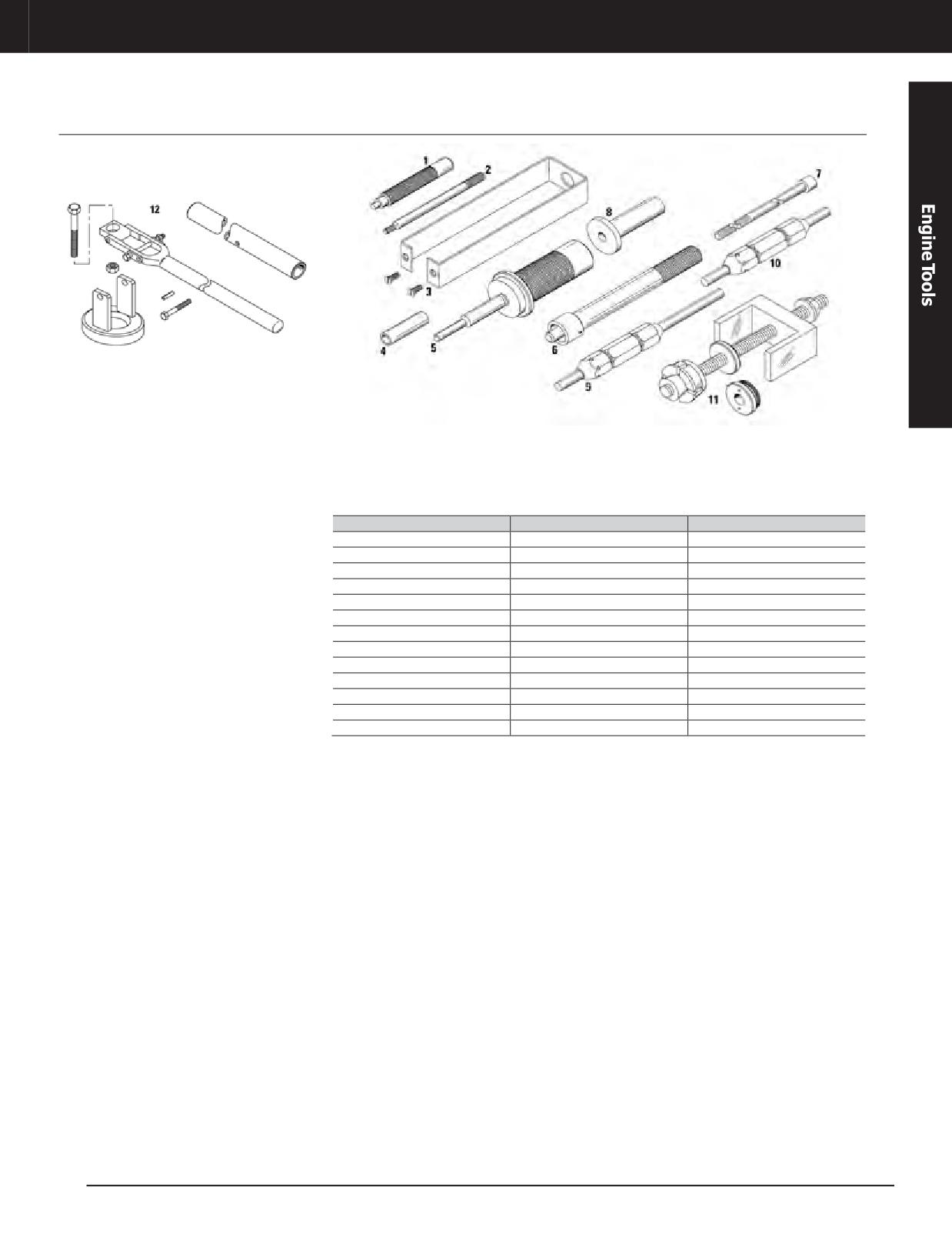
Engine Tools
3600 ENGINE TOOLS
Head Repair Tool Group
Model Usage: All 3600 and G3600 Engines
Warranty: Caterpillar ®Six Months
• Used for general disassembly and assembly of References
Compressor Group (Item 12)
cylinder head
• 3600 and G3600 Engine Service Manuals
Cylinder Head Disassembly and Assembly
Module
Item
Part Number
Description
—
9U-7522
HeadRepairToolGroup
1
4C-8540
Dowel and Plug Driver
2
4C-8731
Dowel Pulling Rod
3
4C-9839
Safety Retainer Group
4
8T-2673
Stop Sleeve
5
8T-2674
Valve Seat Driver
6
8T-2676
Valve Guide Driver Assembly
7
8T-2679
Pulling Rod Assembly
8
8T-2781
Cylinder Support Pedestal
9
9U-6399
Valve Guide Gauge
10
9U-6401
Valve Guide Gauge
11
130-1449
Valve Seat Puller Group
12
8T-2660
Compressor Group
JULY 2018 Engine Tools
3-319
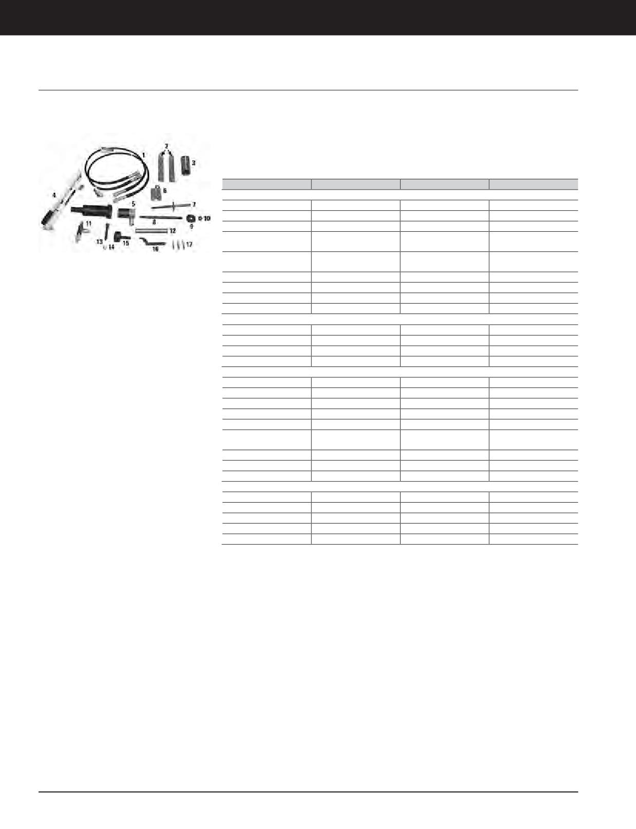
Engine Tools
3600 ENGINE TOOLS
Cylinder Tool Group, Pump Tool Group
Model Usage: 3600 Engines
• Both tool groups used together to disassemble
• Hoses and fittings working pressure:
and assemble 3600 Engine turbochargers
10,000 PSI (68,900 kPa)
Warranty: Caterpillar ®Six Months
• Used with 6V-7030 Micrometer Depth Gauge
Reference
Group (metric) or 6V-2012 Micrometer Depth
• NEHS0615, Tool Operating Manual, 3600
Gauge Group (inches), and 8T-5096 Dial
Turbocharger Disassembly and Assembly
Indicator Group
Item
Part Number
Description
Qty.
9U-6249 Cylinder Tool Group (3600 Turbo) Service/Repair Parts
-
9U-6249
Cylinder ToolGroup
-
2 a
9U-6244
Support
2
5
503-1854
Hydraulic Puller Group
1
Suspension Yoke
6 a
9U-6251
1
Assembly
Removal Housing
11
9U-6255
1
Assembly
13
1D-4614
Bolt
1
14
1D-5119
Jam Nut
1
15
9U-6256
End Plug
1
16
126-8290
Spanner Wrench
1
Not shown
-
1U-7564
Hex Wrench, 5 mm
1
—
1U-7566
Hex Wrench
1
—
4C-9658 b
Case - Protective
1
—
Media Number
NEEG2543. Decal
1
9U-6250 Tool Group, Pump (3600 Turbo) Service/Repair Parts
-
9U-6250
PumpTool Group
-
1
8F-0024
Hose Assembly
2
3
2J-3506
Nut
1
3
9U-6246
Adapter Assembly
1
7
9U-6253
Removal Shaft Assembly
1
Installation Shaft
8
9U-6254
1
Assembly
9
9U-7262
Plate
1
12
9U-6243
Extension Handle
1
17a
9U-6248
Guide Bolt
3
Not shown
-
133-8951
Screw Thrust
-
—
4C-9664 d
Travel Vault
1
—
7J-9108
O-ring Seal c
4
—
9U-6684
Foam Block (top)
1
—
Media Number
NEEG2544, Decal
1
a. Part of 9U-5105 Basic Tool Group, 3600
b. Fold-down handle
c. Supplied with regular foam; Pick-N’Pluck is not available
d. Part of 9U-6253 Removal Shaft Assembly and part of 9U-6254 Installation Shaft Assembly (both assemblies are part of 9U-6250
Pump Tool Group)
3-320 JULY 2018 Engine Tools
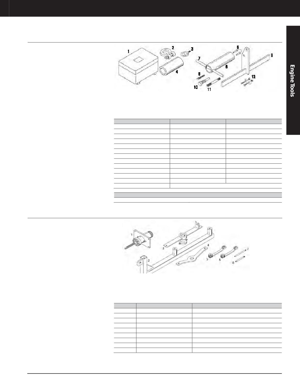
Engine Tools
3600 ENGINE TOOLS
ABB Turbocharger Tool Kit (TPL61)
Model Usage: 3612 Marine Engines
Warranty: Caterpillar ®Six Months
• Used to disassemble and assemble ABB
Reference
TPL61 turbochargers
• REHS0811, Special Instruction, Disassembly
and Assembly of TPL61 Turbocharger
Item
Description
Qty.
1
Tool Box
-
2
Shackle
-
3
Ring Bolt
2
4
Guide Tube
-
5
Radial Bearing Pin
-
6
Press On Bushing
-
7
Bar
-
8
Forcing Screw
4
9
Mounting Supports
2
10
Puller Screw
3
11
Stud
2
12
Press on Tool Assembly
2
Not shown
NEEG2923 Decal
Part Number
Description
195-8104
ABB Turbocharger Tool Kit (TPL61)
Tool Group (NA297)
Essential Tool
Model Usage: 3600 Engines
Warranty: Caterpillar ®Six Months
• Used to disassemble and assemble Napier
Reference
NA297 Turbochargers
• REHS0285, Special Instruction, Disassembly
and Assembly of the Napier NA297
Turbocharger
Item
Part Number
Description
—
187-3703
Tool Group (NA297)
1
177-9811
Turbo ThrustCollar ToolGroup
2
177-9781
Turbo Compressor Lifting Bracket Assembly
3
177-9856
Turbo Impeller Removal Tool Group
4
177-9791
Turbine Locking Tool
5
178-0193
Torque Adapter (30 mm)
6
178-0196
Torque Adapter (1 1/8 in)
7
177-9809
Turbo Bearing Guide Rod
8
177-9852
Insert Guide Rod
JULY 2018 Engine Tools
3-321
Engine Tools
3600 ENGINE TOOLS
Stud Tensioner Tool Group
Essential Tool
European Union compliant, CE marked
• Made of lightweight aluminum for easier use
Model Usage: 3618 Engines
• Allows one-person operation
Stud Tensioner Tool Group
Warranty: Caterpillar ®Six Months
• Used to simultaneously tension four cylinder
• Ideal for tight engine compartments
head studs or two crankshaft main bearing
160-0475 Support Tray
cap studs
• Used to place 153-8488 Cylinder Group onto
• Comes with seal kits for cylinder groups and
156-7168 Main Bearing Cap Handling Group
pump group
• Used with 160-4901 Tray Support Rail
Cylinder Groups
• Recommended but not included
• Smaller, lighter cylinders with convenient
carrying handles
References
• NEHS0762, Tool Operating Manual, Operation
• Pistons return automatically when hydraulic
and Maintenance of the 179-1904 Stud
pressure is released
Tensioner Tool Group Used on 3618 Engines
• Gear driven turning sleeve allows stud nut
• RENR1333, Service Manual, Disassembly and
rotation with 1/2 inch square drive ratchet
Assembly of 3618 Engines
Main Bearing Cap Handling Group
Specifications
• Part of 179-1904 Stud Tensioner Tool Group
• Hydraulic Pump (Electric)
• Air cylinder raises and lowers main
- Maximum pressure: 150 mPa (21,755 PSI)
bearing caps for main bearing inspection or
- Voltage: 230/400 V ( 50/60 Hz)
replacement
- Weight:33 kg (73lb)
Tensioning
Part
Maximum
Overall
Description
Force at Max.
Weight
Number
Stroke
Dimensions
Pressure
161.5 mm
Stud Tensioner
1100 kN at 150
(6.36 in) high
153-8487
Cylinder Group
mPa (247,289 lb
8 mm(0.31 in)
x 143.0mm
9.6 kg (21.16lb)
(Cylinder Head)
at 21,755 PSI)
(5.63 in)
diameter
182.2 mm
Stud Tensioner
2015 kN at 150
10.0 mm
(7.17 in) high x
153-8488
Cylinder Group (Main
mPa (452,990 lb
18.2 kg (40.12lb)
(0.32 in)
188mm (7.4in)
Bearing)
at 21,755 PSI)
diameter
Stud Tensioner Tool
179-1904
-
-
-
-
Group
3-322 JULY 2018 Engine Tools
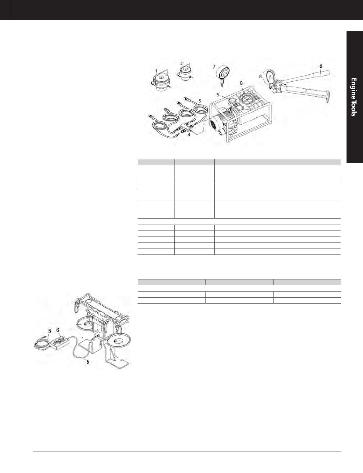
Engine Tools
3600 ENGINE TOOLS
Stud Tensioner Tool Group
Item
Part Number
Description
1
153-8488
Stud Tensioner Cylinder Group (Main Bearing)
2
153-8487
Stud Tensioner Cylinder Group (Cylinder Head)
3
156-7166
Hydraulic Pump, Electric
4
178-9313
DistributionCoupler
5
178-9312
Hose Assembly
6
156-7167
Hydraulic Pump, Manual
7
185-0683
Comparison Gauge
Pressure Gauge (service part for 227-6724, 227-8834, 1 and
8
185-4436
191-5347 Pumps)
Not shown
-
175-0191
Seal Kit (for 191-5323 Main Bearing Cylinder Group)
—
178-9058
Seal Kit (for 191-5322 Cylinder Head Cylinder Group)
—
178-9314
Pump Seal Kit
—
-
Socket Extension (1/2 in drive, 127 mm (5.0 in) long)
—
-
Swivel Head Ratchet (1/2 in drive)
Main Bearing Cap Handling Group
Item
Part Number
Description
156-7168MainBearing Cap Handling Group (part of 179-1904 Stud Tensioner Tool Group)
5
5P-6011
Air Line
6
160-0465
Air Control Box
JULY 2018 Engine Tools
3-323
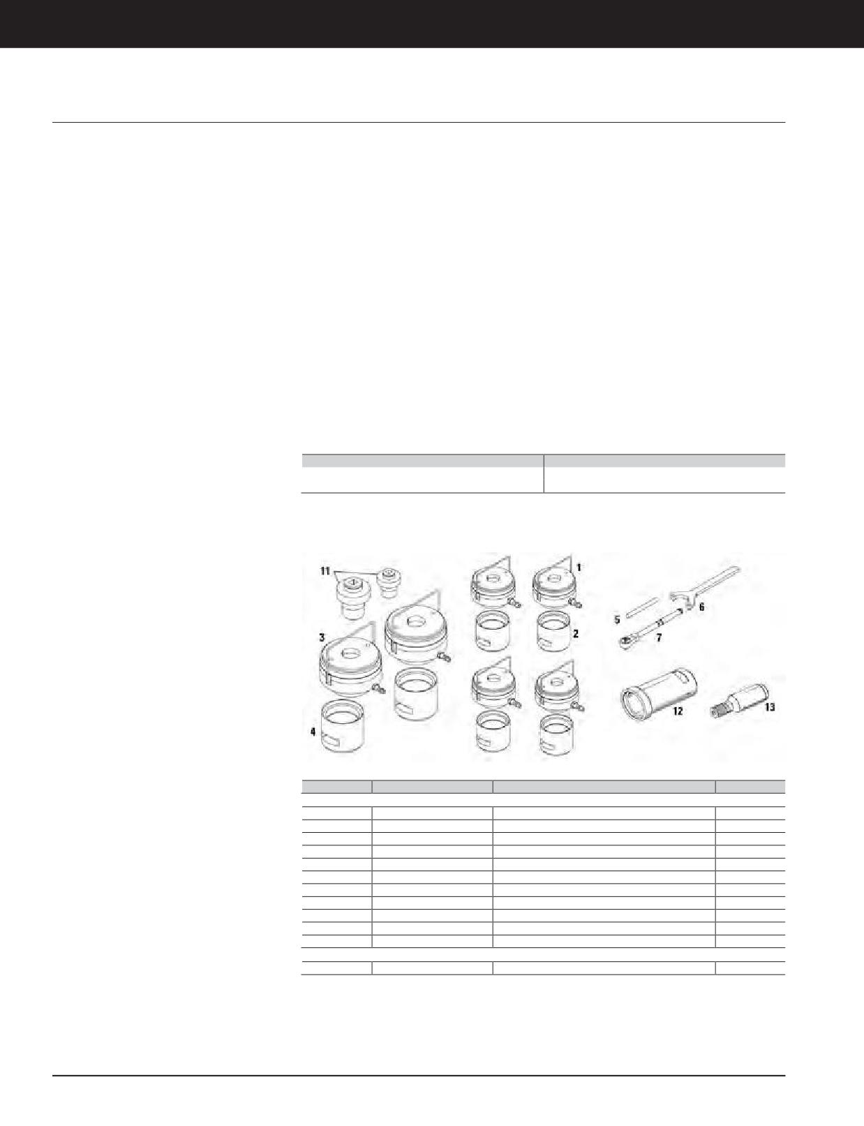
Engine Tools
3600 ENGINE TOOLS
Stud Tensioner Tool Group, Pump Accessory Group
Hydraulic Pumps
European Union compliant, CE marked
References
Model Usage: All 3600 Engines Except 3618
• Used to simultaneously loosen or tighten nuts
• NEHS0866, Operation and Maintenance of
on four cylinder head studs or two crankshaft
Stud Tensioner Tooling Group used on 3600
Warranty: Caterpillar ®Six Months
main bearing cap studs
Engines (except 3618)
• Used with 8T-0960 Handling Tool Group
• SENR4259, Disassembly and Assembly G3606
for easier removal and installation of main
and G3608 Engines
bearing caps
• SENR5535, Disassembly and Assembly G3612
• Requires one 301-5215 Group, one 229-9453
and G3616 Engines
Group, and one of optional pumps listed
• SENR3600, Disassembly and Assembly 3606
(cannot be used with any other pumps except
and 3608 Engines
the ones listed as item 10)
SENR3594, Disassembly and Assembly 3612
•
• Compact, lightweight cylinders have
and 3616 Engines
convenient carrying handles
• Optional gear drive permits faster installation
of nut onto stud (1/2 inch square drive ratchet)
• ISO9001 Certified
Part Number
Description
229-9453
Pump Accessory Group
301-5215
Stud Tensioner Tool Group
Basic Tooling Required for 301-5215 Stud Tensioner Tool Group
Item
Part Number
Description
Qty.
301-5215 Stud Tensioner Tool Group (required)
1
191-5322
Cylinder Head Cylinder Group
4
2
191-5333
Cylinder Head Support
4
3
191-5323
Main Bearing Cylinder Group
2
4
191-5335
Main Bearing Support
2
5
9U-5141
Nut Turning Handle
2
6
-
Spanner Wrench
-
7
-
Swivel Head Ratchet (1/2 in square drive)
-
11
191-5324
Bushing (for 191-5322 Group)
4
11
191-5326
Bushing (for 191-5323 Group)
2
12
225-5637
Support (usedwith 191-5322 and 191-5324)
2
13
225-5636
Adapter (used with 191-5322 and 191-5324)
2
Not Shown
-
253-3272
Main Bearing Cylinder Group (C175)
2
NOTE: Adapter and support bushing are required for front cylinder heads adjacent to support
bracket.Taller adapter and support provides necessary clearance.
3-324 JULY 2018 Engine Tools
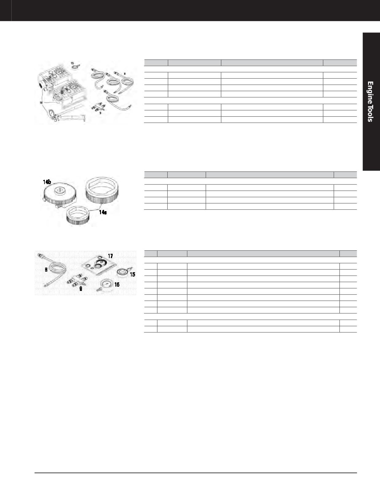
Engine Tools
3600 ENGINE TOOLS
Basic Tooling Required
Item
Part Number
Description
Qty.
Pumps, Hose, and Coupler (requires one 229-9453 Group and one pump option)
10
156-7167
Hydraulic Pump, Manual
-
10
191-5347
Hydraulic Pump, Pneumatic
1
10
227-6724
Hydraulic Pump, Electric, 120 V
1
10
227-8834
Hydraulic Pump, Electric, 240 V
1
229-9453 Pump Accessory Group Includes:
8
178-9312
Hose Assembly
4
9
178-9313
DistributionCoupler
1
15
185-0683
Comparison Gauge
1
Optional Tooling
Item
Part Number
Description
Qty.
Optional Gear Drive Group (permits faster rotation of nut onto stud)
14
191-5341
Gear Drive Group (optional, includes items 14a and 14b)
1
14a
191-5343
Turning Sleeve (for 191-5322 Cylinder Head Cylinder Group)
4
14a
192-4316
Turning Sleeve (for 191-5323 Main Bearing Cylinder Group)
2
14b
191-5342
Gear Drive Assembly
6
Service/Repair Parts
Item
Part Number
Description
Qty.
Service/Repair Parts
8
178-9312
Hose Assembly
1
9
178-9313
DistributionCoupler
1
15
185-0683
Comparison Gauge
1
16
185-4436
Pressure Gauge (service part for 227-6724, 227-8834, 191-5347 Pumps)
1
17
175-0191
Seal Kit (for 191-5323 Main Bearing Cylinder Group)
1
17
178-9058
Seal Kit (for 191-5322 Cylinder Head Cylinder Group)
1
17
194-8202
Seal Kit (for 191-5347 Pump)
1
17
227-6725
Seal Kit (for 227-6724 Pump and 227-8834 Pump)
1
Not Shown
-
253-3275
Seal Kit (for 253-3272 Main Bearing Cylinder Group)
-
—
253-3276
DistributionCoupler
-
JULY 2018 Engine Tools
3-325
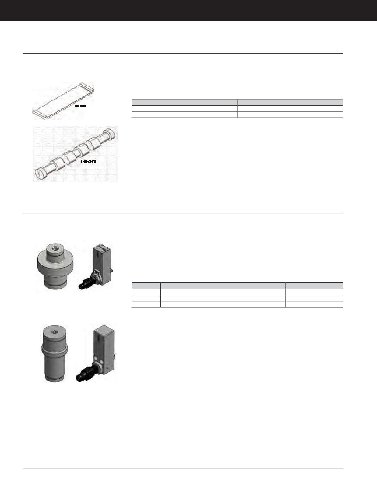
Engine Tools
3600 ENGINE TOOLS
Support Tray
Model Usage: 3618 Engines
• Used to support 153-8488 Tensioning Cylinder
Reference
being manually placed onto 156-7168 Bearing
Warranty: Caterpillar ®Six Months
• RENR1333, Service Manual, Disassembly and
Cap Handling Group
Assembly of 3618 Engines
• Traysupport rail easily fits onto engine oil pan
baffles
Part Number
Description
160-0475
Support Tray
Support Tray Rail
Cycle Counter Kits
Model Usage: All C175, C280, 3600
• This field-installable cycle counter upgrade
Kit Includes:
allows monitoring the life cycle of the change
Warranty: Manufacturer’s
• New cycle counter block
bushing.
• New change bushing
• Replacement of bushings recommended at
• Newseal repair kit
approximately 2000 cycles.
• Complete instructions
• Contact information for questions or
assistance
Part No.
Dimensions
Weight
457-3253
330x178 x178mm (13x7x7in)
4.1 kg (9 lb)
Bushing And Hydraulic Block For 457-3253
457-3254
330x178 x178mm (13x7x7in)
6.4 kg (14 lb)
(Retrofit 3600 Head) and 457-3254
457-3255
254 x 152 x 101.6 mm (10 x 6 x 4 in)
3.2 kg (7 lb)
(Retrofit-3600 Main Bearing)
Bushing And Hydraulic Block For 457-3255
(Retrofit- C175 Main Bearing)
3-326 JULY 2018 Engine Tools
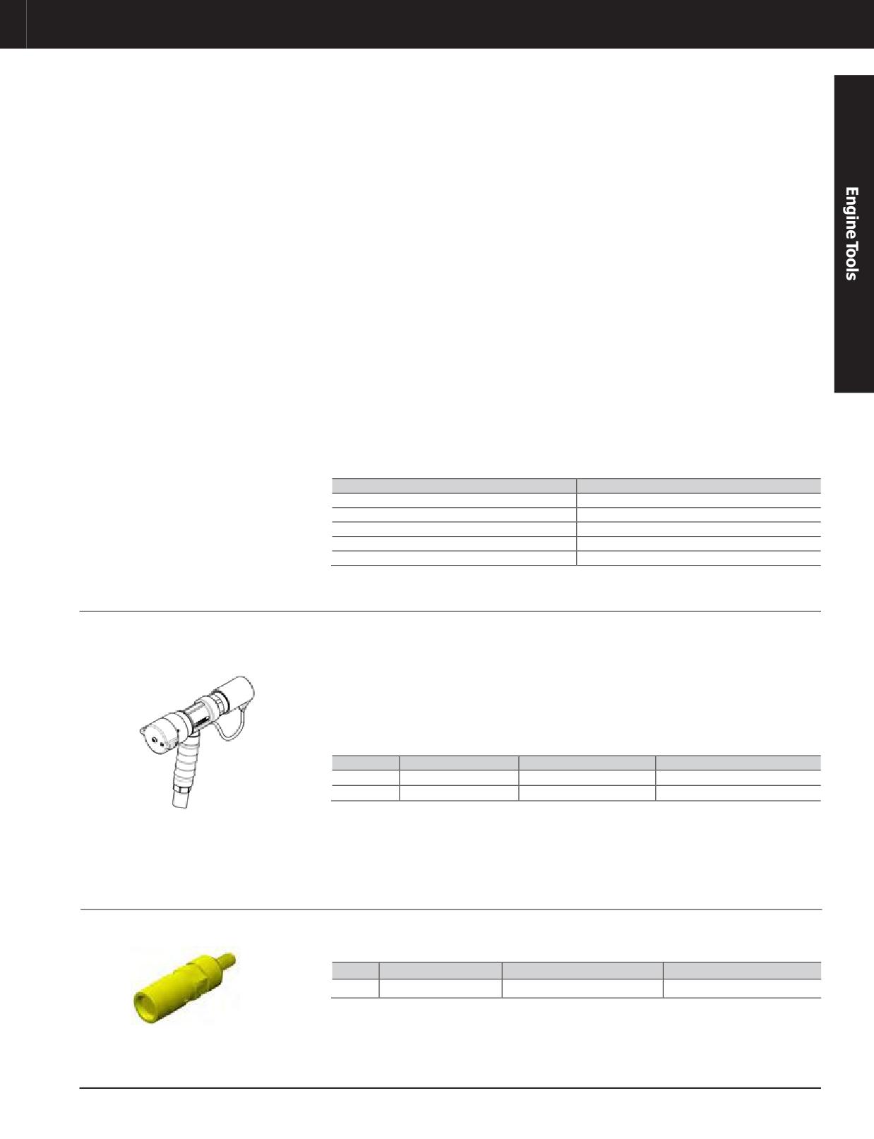
Engine Tools
3600 ENGINE TOOLS
Optional Tooling
• 191-5322 Cylinder (Cylinder Head Studs):
• 227-6724 and 227-8834 Electric Hydraulic
- Maximum tensioning force: 1100 kN
Pump:
(247,289 lb)
- Oil quantity: 3.8 L (0.84 gal)
- Maximum operating pressure: 150 mPa
- Maximum operating pressure: 150 mPa
(21,755 PSI)
(21,755 PSI)
- Effective piston surface: 73.2 cm²
- Voltage, frequency: 120/240 V, 60/50 Hz
(11.35 in 2)
- Weight:33 kg (73lb)
- Stroke: 10.0 mm (0.39 in)
• 191-5347 Pneumatic Hydraulic Pump:
- Weight: 9.5 kg (21 lb)
- Oil quantity: 4.0 L (0.88 gal)
• 191-5323 Cylinder (Main Bearing Cap Studs):
- Maximum operating pressure: 150 mPa
- Maximum tensioning force: 2015 kN
(21,750 PSI)
(452,990 lb)
- Air pressure: 3.5 - 8 bar (51 - 116 PSI)
- Maximum operating pressure: 150 mPa
- Air consumption: 104 - 206 gpm
(21,755 PSI)
- Weight: 22 kg (48.5 lb)
- Effective piston surface: 134.3 cm²
• Oil Specifications:
(20.8 in 2)
- Oil viscosity at 50°C (122°F): 1.75 E-9.1
- Stroke: 10.0 mm (0.39 in)
Centistokes
- Weight: 19.5 kg (43 lb)
- Oil temperature (maximum):60°C (140°F)
- Oil approval: HLP10 nach/acc.to VDMA
24318 bzw./resp. DIN51525
Part Number
Description
191-5322
Cylinder Head Cylinder Group
191-5323
Main Bearing Cylinder Group
191-5347
Hydraulic Pump, Pneumatic
227-6724
Hydraulic Pump, Electric, 120 V
227-8834
Hydraulic Pump, Electric, 240 V
Fast-Fill DEF Nozzle (Ground Level)
Model Usage: Cat® Machines with Ground-Level
• Improved design replaces the cancelled
• No-Spill design offers clean fluid break and
DEF Fill Option
449-3224
does not allow dust or dirt into system
Warranty: Manufacturer’s
• 3/4 inch hose barb makes connecting to
• All metal exterior components make it
standard type dispensing hose a breeze
suitable for any field environment
• Unique interface eliminates possibility of
• When tank is full, the cap snaps back into
cross contamination with other fluids
place and rotates 60 degrees, while revealing
a red ring that provides visual cue to operator
Part No.
Description
Dimensions
Weight
506-8793
Fast-Fill DEF Nozzle
245 X 230 mm (9.64 x 9.05”)
3.9 kg (8.7lb)
453-1650
Cap
52.7 X 69 mm (2.07 X 2.7”)
0.06 (est) kg (0.12 lb)
For warranty/repair info, contact Hartmann
Controls, 604 Progress Dr, Hartland, WI 53029.
262-367-4299
DEF Nozzle Purge Tool
Warranty: Manufacturer’s
• This tool purges DEF from the 506-8793 DEF
nozzle after use.
Part No.
Description
Dimensions
Weight
509-7101
DEF Nozzle Purge Tool
169 x 49 mm (6.7 x 2 in)
1.6 kg (3.5 lb)
JULY 2018 Engine Tools
3-327
Engine Tools
3600 ENGINE TOOLS
Diesel Exhaust Fluid (DEF) Truck Tank
Model Usage: All Machines Requiring DEF
• All stainless steel frame to hold tank
• 32 gallon polyethylene tank meets ISO
construction— will not be attacked by DEF
standards for proper storage of DEF
Warranty: Manufacturer’s
or weather
• 71 gallon polyethylene tank meets ISO
• Truck pan constructed to bolt to truck bed
standards for proper storage of DEF
with vertical and horizontal slotted holes for
Specifications
optimal placement
• Size: 71 Gallon
• Self-Priming 12 Volt - 7 GPM DEF Pump with
12' Power Cord, in-line fuse and battery clips
• Dimensions: 1,219 x 533 x 914 mm (48 x 21
x 36 in)
• Custom designed to mount behind truck bed
diesel tank between the wheel wells
• Weight: 45 kg (99 lb)
Part No.
Description
460-4078
Diesel Exhaust Fluid Truck Tanks (Made Asd Ordered)
DEF Dispenser
Model Usage: All Machines and Engines using
• Used to dispense DEF (Diesel Exhaust Fluid)
Specifications
DEF
from a 1000 liter (264.2 gal.) tote
• Dispenser comes packaged with necessary
Warranty: Manufacturer’s
• Optional coupler (423-7799) and flowmeter
hardware for installation:
(423-7795) are available
- Stainless steel centrifugal pump
- 20 ft (6.1 m) discharge hose
• Unit mounts directly to tote
- 6 ft (1.8 m) electrical cord
• Simple to install
- 4 ft (1.2 m) suction hose
• Flow rate: 8.5 gpm to 9.5 gpm (32.2 lpm to
- Stainless steel automatic nozzle with hose
35.9 lpm)
barb swivel
- 4 hose clamps
• Requires 13 amp @ start (110 Volt unit) or 7
- 2 tote elbow brackets
amp @ start (230 volt unit)
Part No.
Dimensions
Power
423-7843
559 x 483 x 457 mm (22 x 19 x 18 in)
110 VAC, 60hz
423-7944
559 x 483 x 457 mm (22 x 19 x 18 in)
230 VAC, 60hz
456-8816
Dia 175 x 150 mm (0.520 kg)
DEF Dispensing Unit
Model Usage: All Tier 4 Machines
• Cold weather stationary power-dispensing
• 2 ft of 1/8 inch diesel fuel hose
unit made of stainless steel, polyurethane,
Warranty: Manufacturer’s
• Petu tank stand (stainless steel)
powder-coated carbon steel
• 24-volt power relay
• Insulation to negative 40°F
• 24-volt DEF transfer pump
• 2 locking door handles
• 24-volt DEF transfer pump mounting bracket
• Diesel air heater
• Stainless steel interface plate
• 1 fuel-metering pump
• 2-inch cam to 3/4 inch house barb
• 2 ft of combustion air inlet hose
(for tote integration)
• 18 inches of exhaust outlet hose
• 500-gallon tank
• 2.5 gallon diesel tank
• Trailer not included
Part No.
Description
472-2065
DEF Dispensing Unit
3-328 JULY 2018 Engine Tools
Engine Tools
3600 ENGINE TOOLS
DEF Dispensing Unit Repair Parts and Year-Round Enclosures
Model Usage: All
• 435-8671 a - used to protect tote from
• 435-8672 b - used to protect tote from
elements
elements
Warranty: Caterpillar ®One Year
i
478-1150
436-6642 c
436-6643 e
436-6647 d
436-6644 f
436-6645 g
436-6646 h
a. Warm weatherenclosure: 2209 x 1219 x 2159 (87 x 48 x 85 in)
b. Cold weather enclosure: 2209 x 1219 x 2159 (87 x 48 x 85 in)
c. Hoses used on dispensing units 422-1185, 423-7843, 423-7844: 609.6 & 121.9 cm (20 & 4 ft)
d. Nozzle used on dispensing units 422-1185, 423-7843, 423-7844
e. Pump repair group used on 422-1185 12 volt pump group
f. Swivel used on dispensing units 422-1185, 423-7843, 423-7844
g. Repair group: 1/2 HP pump
h. 12 V Repair group used on 422-1185 12 volt pump group
i.
Used to cover the 436-6647 nozzle spot during transport of DEF
JULY 2018 Engine Tools
3-329