Caterpillar. 279C, 289C and 299C Compact Track Loaders. Operation and Maintenance Manual - page 2
100
SEBU8407-06
Operation Section
Parking
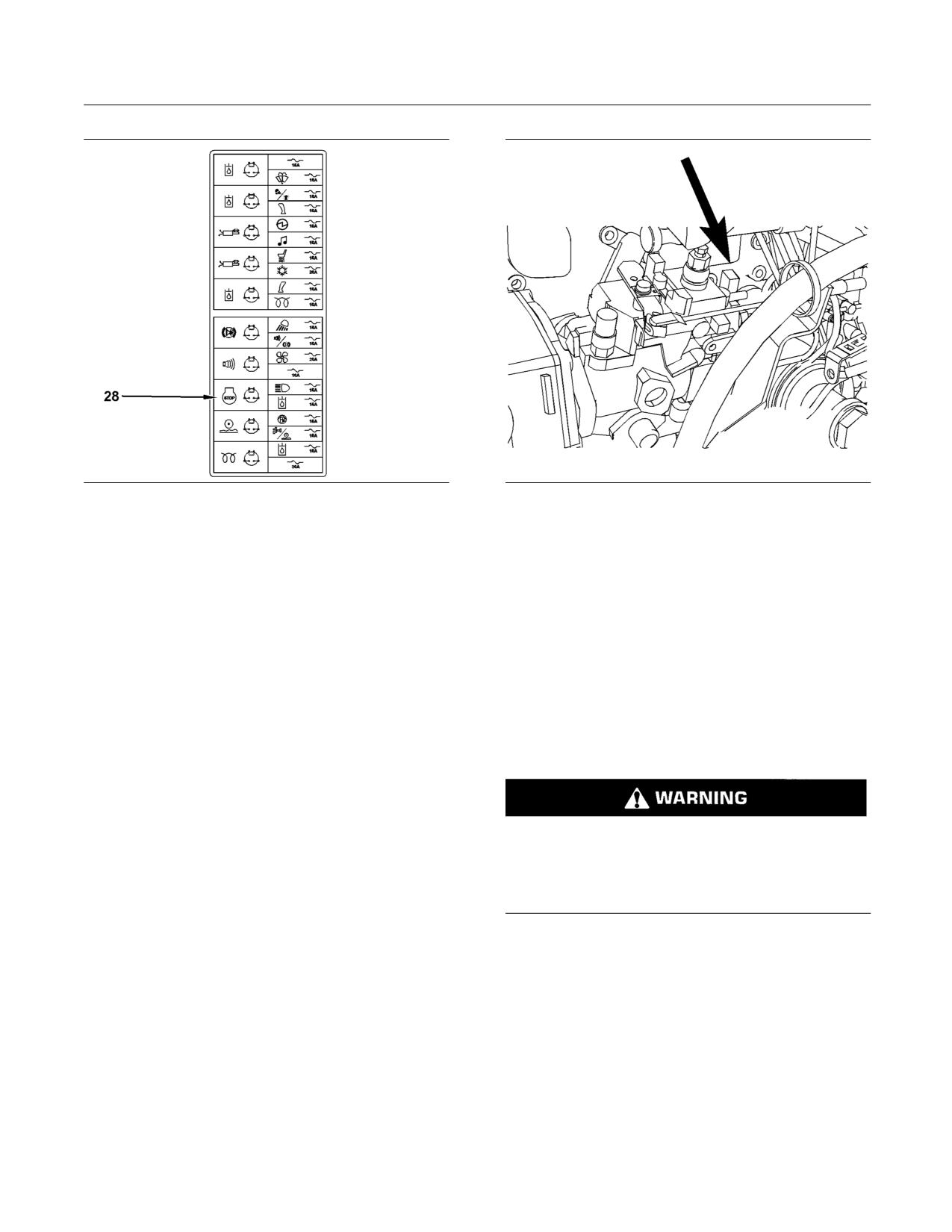
g01330924
g01289102
Illustration 79
Illustration 80
The connector for the fuel shutoff solenoid is located on the back
Remove the relay for the fuel shutoff solenoid (28) in
of the fuel pump.
order to shut off the fuel supply to the engine.
4. Unplug the connector for the fuel shutoff solenoid.
Note: Do not operate the machine until the
malfunction has been corrected.
Note: Do not operate the machine until the
malfunction has been corrected.
Outside Cab
i02807964
1. Lower the work tool to the ground.
Equipment Lowering with
2. Raise the armrests. Unfasten the seat belt. Exit
Engine Stopped
the machine.
SMCS Code: 6700; 7000
3. Open the engine access door. Refer to Operation
and Maintenance Manual, “Access Doors and
Covers”.
Personal injury or death can result from a work
tool falling.
Keep personnel away from the front of the ma-
chine when lowering the work tool.
Before lowering any equipment with the engine
stopped, clear the area around the equipment of all
personnel. The procedure will vary with the type of
equipment that is lowered. Keep in mind that most
systems use a high pressure fluid or air in order to
raise or lower the equipment. The procedure will
cause high pressure air, hydraulic fluid, or some other
media to be released in order to lower the equipment.
Wear appropriate personal protective equipment and
follow the established procedure in the Operation
and Maintenance Manual, “Equipment Lowering with
Engine Stopped” in the Operation Section of the
manual.
SEBU8407-06
101
Operation Section
Parking
Lowering the Equipment with the
Accumulator Charged
If electrical power is available and the accumulator
is charged, the loader arms can be lowered from the
operator station with the work tool control.
1. Fasten the seat belt. Lower the armrests.
2. Move the engine start switch to the ON position.
Press the parking brake switch and release the
parking brake switch.
Note: The parking brake indicator will remain
illuminated since the engine is not running. When the
indicator for the work tool is no longer illuminated, the
pressure can be released.
3. Slowly move the work tool control to the LOWER
position in order to slowly lower the loader arms.
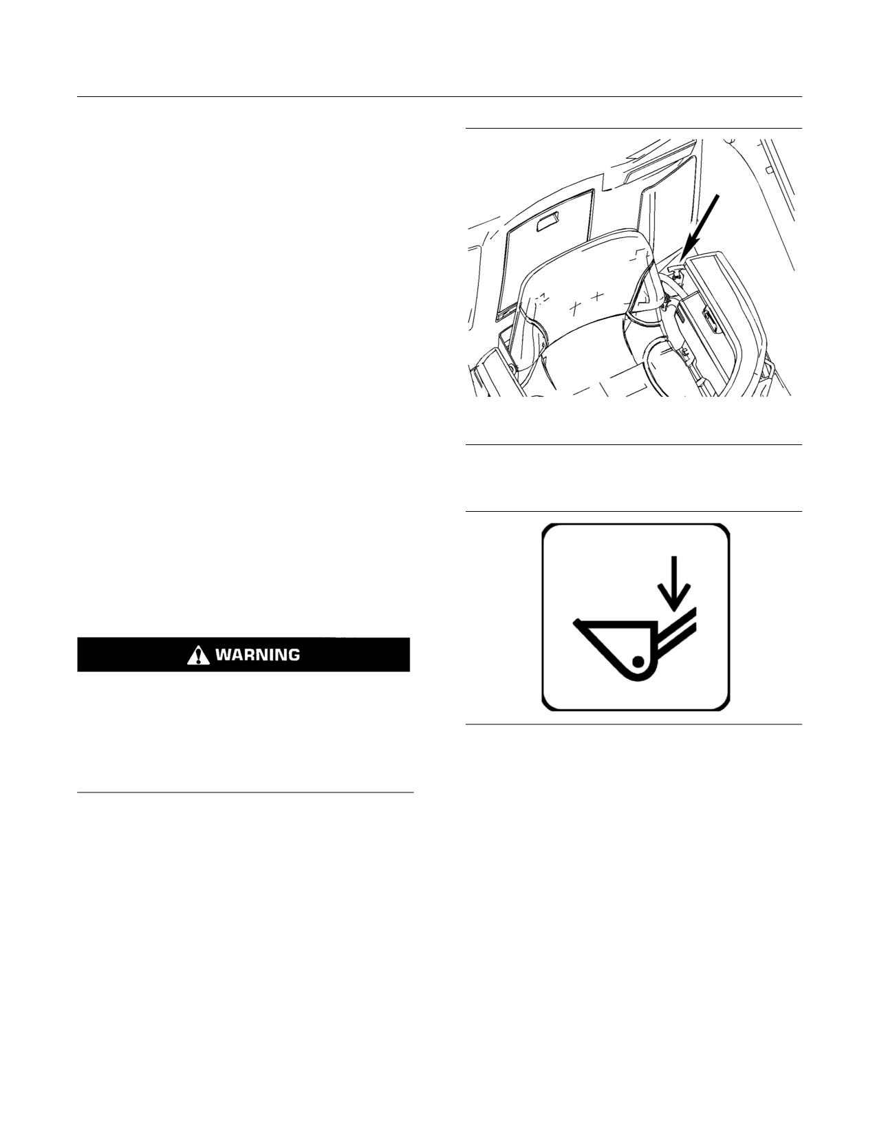
g01400888
If the loader arms do not lower, the accumulator is not
Illustration 81
charged. It is possible to recharge the accumulator by
The bypass valve is located on the left side next to the seat in
cranking the engine for a period of fifteen seconds.
the cab.
Repeat step 2 and 3.
If there is no electrical power the loader arms must
be lowered by using the procedure that is explained
next.
Alternate Lowering the Equipment
Personal injury can result from oil under high
pressure.
DO NOT allow high pressure oil to contact skin.
g01332374
Illustration 82
Film next to the red knob
Wear appropriate protective equipment while
working with high pressure oil systems.
1. Slide the seat forward. Slide the left hand armrest
forward.
The loader arms must be lowered manually if the
accumulator is not charged or if there is no electrical
2. Pull up on the red handle. Push the handle in
power.
order to stop the loader arms, if necessary.
Do not go under the raised lift arm without the brace
3. Allow the loader arms to lower until the work tool
for the loader lift arm in the LOCKED position.
is on the ground.
Note: Make sure that there are no people near the
4. Push the red handle to the original position.
front or sides of the machine.
5. Make the necessary repairs before you operate
the machine.
102
SEBU8407-06
Operation Section
Parking
i01956123
7. Add .15 mL (0.02 oz) of commercial biocide for
every 1 L (0.3 US gal) of calibration fluid to the fuel
Machine Storage Procedure
tank. Seal all openings to the fuel tank in order to
prevent evaporation of the preservative.
SMCS Code: 7000
NOTICE
If long term storage for a period of time exceeding one
year is necessary, contact your local Caterpillar deal-
er for the preferred procedure to use in your specific
case.
This machine may be stored for one year or less in
a temperature range of -32 °C (-25.6 °F) to 43 °C
(109.4 °F).
To store machines in ambient temperatures between
-20 °C (-4.0 °F) to 43 °C (109.4 °F), refer to Special
Instructions, SEHS9031, “Storage Procedure for
Caterpillar Products”.
To store machines in ambient temperatures between
-32 °C (-26 °F) and -21 °C (-6 °F), refer to the
following publications and topics:
• Special Instructions, SEHS9031, “Storage
Procedure For Caterpillar Products”
• Operation and Maintenance Manual, SEBU5898,
“Cold Weather Recommendations for Caterpillar
Machines”
Note: Do not use the steps that are listed in Special
Instructions, SEHS9031 in order to maintain the fuel
system.
Use the following steps to maintain the fuel system.
1. Drain the fuel tank. Follow the procedure that is
described in Operation and Maintenance Manual,
“Fuel Tank Water and Sediment - Drain”.
2. Drain the water separator and replace the
element. Follow the procedure that is described
in Operation and Maintenance Manual, “Fuel
System Water Separator Element - Replace”.
3. Fill the fuel tank so that the fuel tank is at least
20% full with Calibration Fluid.
4. Prime the fuel system. Follow the procedure that is
described in Operation and Maintenance Manual,
“Fuel System Prime”.
5. Start the engine and run at low idle for
approximately 15 minutes in order to allow the
calibration fluid to flush the diesel fuel from the
system.
6. Turn off the engine.
SEBU8407-06
103
Operation Section
Transportation Information
2. When you use loading ramps, make sure that the
Transportation Information
loading ramps have adequate length, adequate
width, and adequate strength. In addition, make
i02520157
sure that the surface of the loading ramps are
clean. This will help prevent the machine from
Shipping the Machine
sliding in all types of weather conditions. This will
allow the machine to move on the ramps smoothly.
SMCS Code: 7000
3. Maintain the slope of the loading ramps within 15
Investigate the travel route for overpass clearances.
degrees of the ground.
Make sure that there will be adequate clearance.
4. Minimize any step between the base of the loading
Before you load the machine and before you unload
ramps and the ground.
the machine remove ice, snow, or other slippery
material from the loading dock and from the trailering
5. Clean the tracks on the machine in order to
surface. Removal of ice, snow, or other slippery
prevent any slippage.
material will help prevent the slipping of the machine
as you load the machine. Removing ice, snow, or
Loading the Machine
other slippery material will help prevent the machine
from moving in transit.
1. Position the machine so that the heaviest end of
the machine is going up the ramps first.
NOTICE
Obey all state and local laws governing the weight,
2. Use caution when you travel over the areas
width and length of a load.
around the loading ramp joints. Maintain the
balance point of the machine. Keep the work tool
Make sure the cooling system has proper antifreeze if
low.
moving machine to a colder climate.
3. After you load the machine onto the trailer be sure
Observe all regulations governing wide loads.
that the machine is properly positioned on the
trailer bed.
Do not use a fork lift to lift the machine. Using a
4. Lower the work tool to the floor of the transport
fork lift to move your machine can result in property
vehicle.
damage.
5. Turn the engine start switch key to the OFF
Choose the flattest ground when you load the
position in order to stop the engine.
machine or when you unload the machine.
6. Turn the engine start switch key to the ON
position. Push the parking brake switch.
7. Move all joystick controls while you are pressing
several times on each side of the auxiliary
hydraulic control (if equipped) in order to relieve
hydraulic pressure.
8. Move all hydraulic controls to the NEUTRAL
position.
9. Turn the engine start switch key to the OFF
position. Remove the engine start switch key.
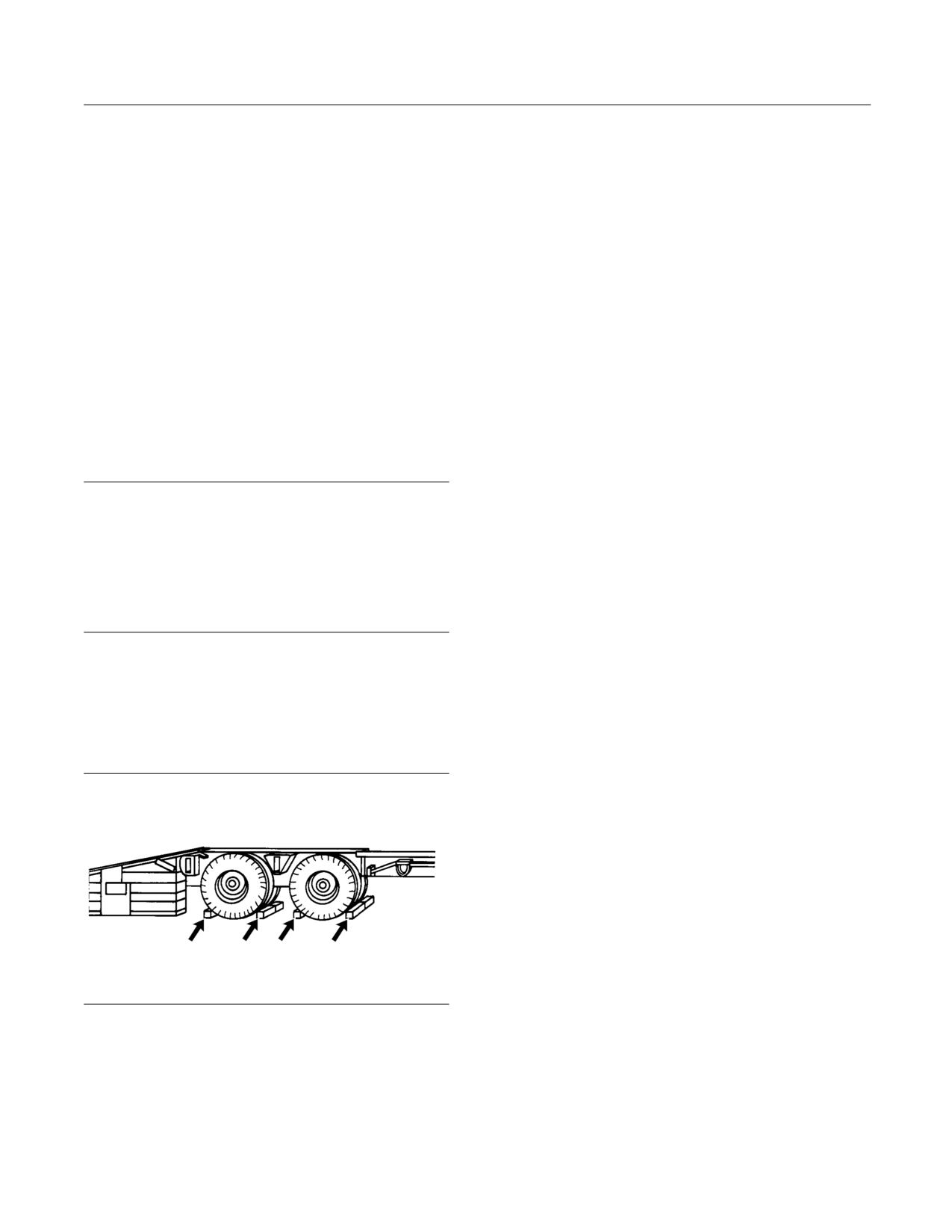
g00040011
10. Move the armrests to the RAISED position.
Illustration 83
Unfasten the seat belt.
1. Before you load the machine chock the trailer
11. Attach any vandalism protection.
wheels or the rail car wheels. Before you unload
the machine chock the trailer wheels or the rail
12. Refer to the Operation and Maintenance
car wheels.
Manual, “Lifting and Tying Down the Machine” for
information on tying down the machine.
104
SEBU8407-06
Operation Section
Transportation Information
13. Cover the exhaust opening when the machine
• The four-point lifting group
has cooled down.
Use one of the lifting attachments in order to lift the
machine. Do not attach both lifting devices to the
Unloading the Machine
machine at the same time.
1. Position the machine so that the machine can
For lifting the machine, use properly rated cables and
drive straight down the loading ramps. Position the
properly rated slings. Position the crane for a level
machine so that the heaviest end of the machine
machine lift. Do not drag the machine with a crane.
goes down the ramps last.
All work tools must be removed from the machine
2. Use caution when you travel over the areas
before the machine is lifted.
around the loading ramp joints in order to maintain
the balance point of the machine. Keep the work
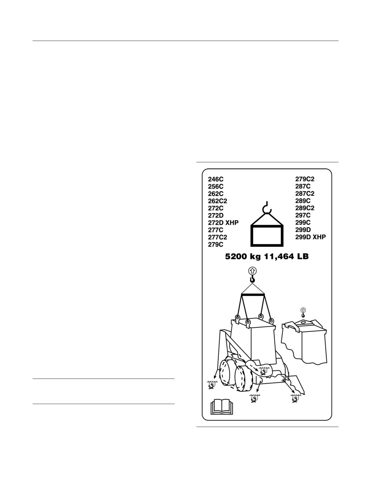
Note: Do not exceed the weight limit that is shown
tool low.
in Illustration 84. This film is located on the outside
of the right-hand side of the cab.
i03886175
Roading the Machine
SMCS Code: 7000
Limitations for TON-kilometers per hour (TON-miles
per hour) must be obeyed. Consult your tire dealer
for the speed limit of the tires that are used.
Ensure that you have the required licenses and other
similar items with you while you road the machine.
Ensure that your machine is equipped to comply with
roading regulations.
Learn and obey all traffic regulations when you are
roading the machine. Travel at a moderate speed.
Observe all speed limitations when you road the
machine. Ensure that all work tools remain securely
attached to the work tool coupler. Ensure that
appropriate locking pins remain in position.
Note: In Italy, limit Skid Steer Loaders that are
equipped with two speed to low speed while roading.
i04777219
Lifting and Tying Down the
Machine
SMCS Code: 7000
NOTICE
Improper lifting or tiedowns can allow load to shift and
can cause injury and damage.
Lifting the Machine
g02623980
There are two lifting attachments for the machine:
Illustration 84
• The single point lifting eye
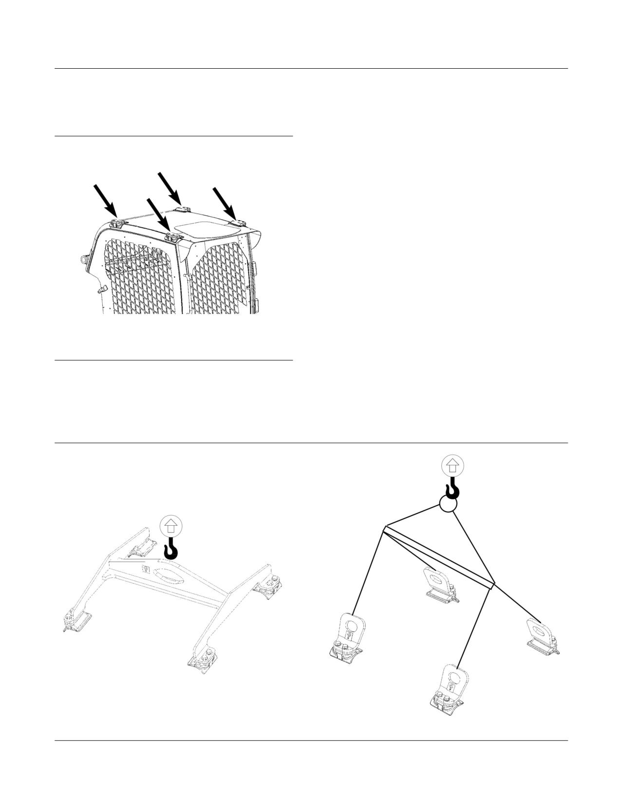
SEBU8407-06
105
Operation Section
Transportation Information
The lifting devices will be mounted on the top of the
cab. If any accessory is mounted to the cab roof,
the attachment must be removed before lifting the
machine.
g02838517
Illustration 85
Points for attaching the lifting devices
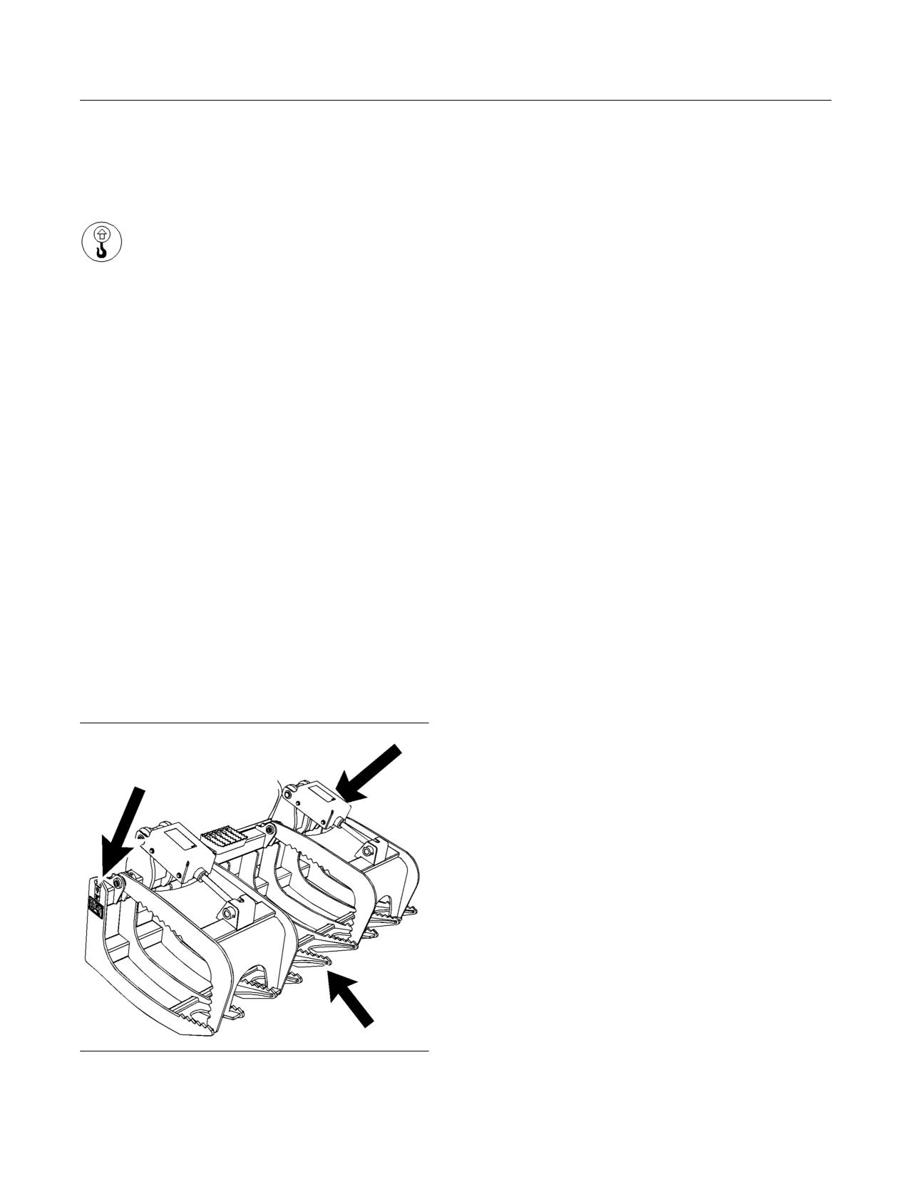
When the four-point lifting group is used, the chain
for each leg should be a minimum of 1 m (3.3 ft) in
length. Keep the machine level during the lift.
g02838519
Illustration 86
106
SEBU8407-06
Operation Section
Transportation Information
Refer to the Cat Parts Manual for the current part
Use properly rated cables and properly rated slings
number for the lifting device for your machine.
for lifting work tools. Position the crane for a level lift.
The parts manuals are listed in the Operation
Do not drag the work tool with a crane.
and Maintenance Manual, “Reference Information
Section”.
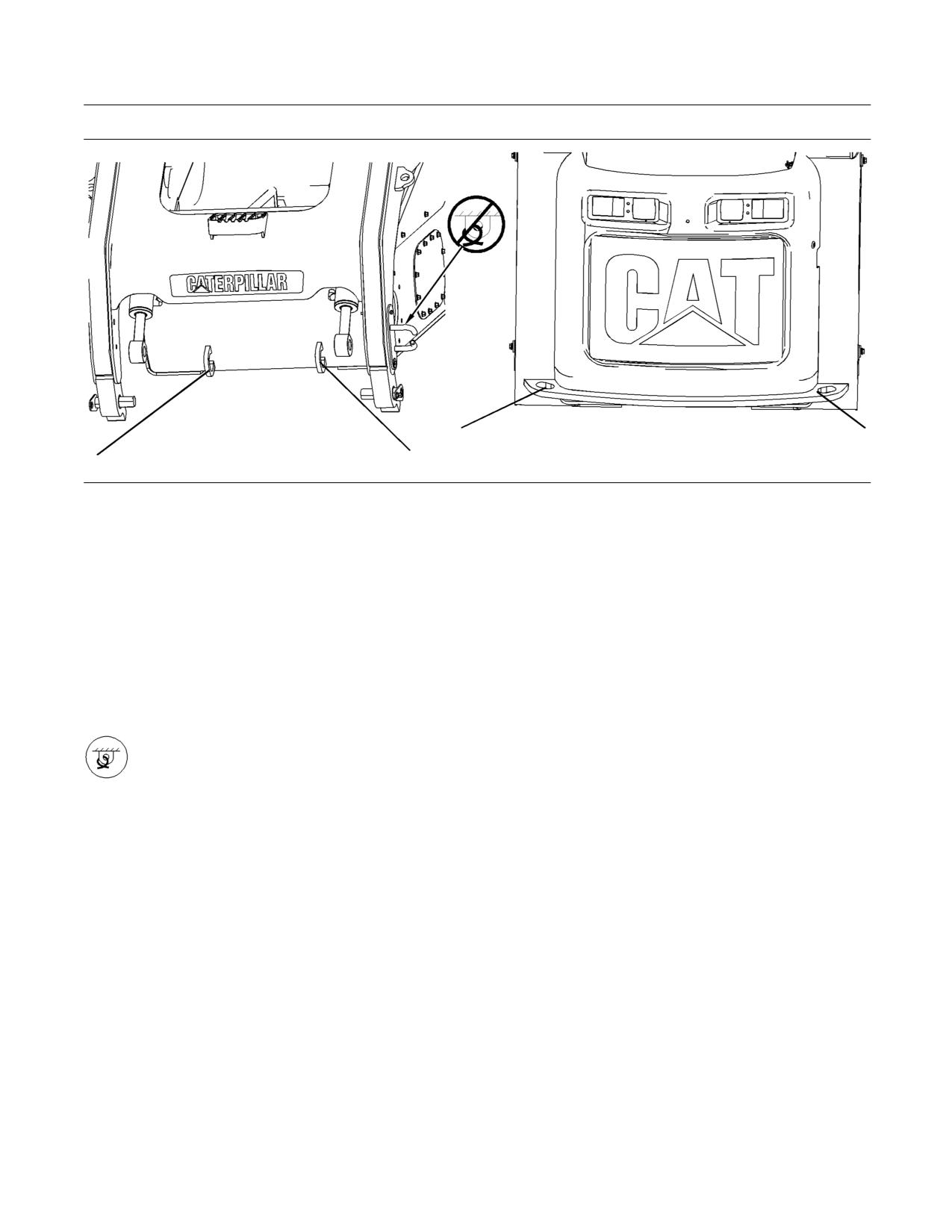
Note: The approximate weight of the 1829 mm
(72 inch) Grapple Rake is 458 kg (1010 lb). The
Lifting Point - Lifting points are
approximate weight of the 2134 mm (84 inch)
designated by this symbol.
Grapple Rake is 506 kg (1116 lb).
Use two hooks in the lifting eyes on the frame. Use
a sling around the front torque tube at the center
The weight and the instructions that are given
rake tine.
describe the machine as manufactured by Caterpillar.
Refer to the Operation and Maintenance Manual,
“Specifications” for weight information about your
Tying Down the Machine
machine.
There may be more than one way to tie down
Do not allow any personnel in the area around the
the machine. Local regulations should be used
machine.
to determine the best method. Obey all local and
regional governmental regulations.
1. Remove the work tool. If necessary, cover any
hydraulic lines and quick disconnect coupler on
the machine.
2. Lower the lift arms completely.
3. Turn off the machine.
4. Attach the single point lifting device or the four
point lifting device to the machine.
5. Use properly rated cables and slings for lifting.
The crane should be in a position that the machine
is lifted without swinging.
Lifting the Grapple Rake
g01368478
Illustration 87
SEBU8407-06
107
Operation Section
Transportation Information
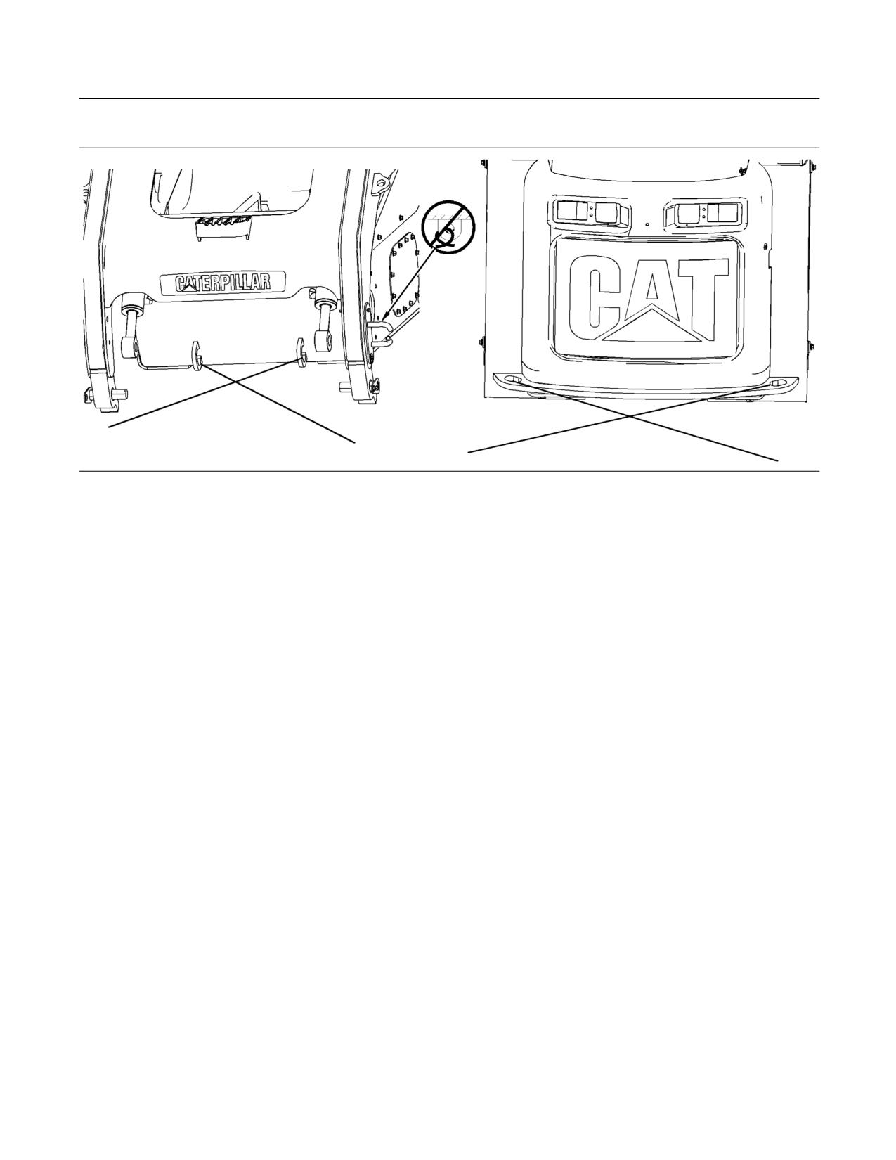
g02882786
Illustration 88
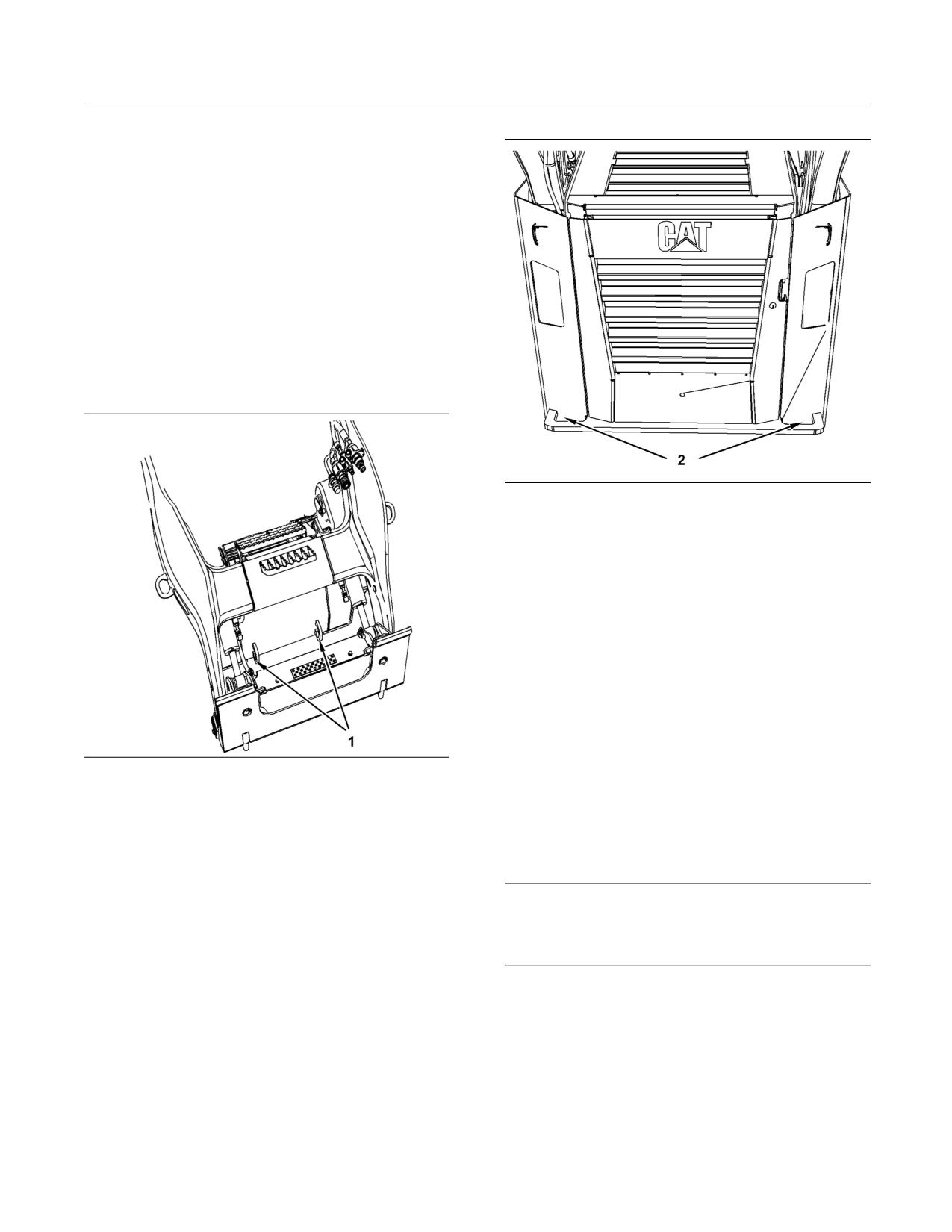
Two eyes are located on the front of the machine frame and two eyes are located on the rear of the machine frame.
Use the tie-downs shown in illustration 88.
Note: Use only the specified locations for tying down
the machine. Do not use any other locations in order
to tie down the machine. The eyes on the lift arms
are for work tool restraint only. Never use the eyes
on the lift arms for tie down or lifting.
Install tie-downs at all four locations. Place chocks in
front of the machine and behind the machine.
Tie-Down Point - Tie-down points are
designated by this symbol.
The weight and the instructions that are given
describe the machine as manufactured by Caterpillar.
Refer to the Operation and Maintenance Manual,
“Specifications” for weight information about your
machine.
1. Turn off the machine.
2. Use the properly rated cables and shackles for
tying down the machine.
3. Use the front eyes and the rear eyes that are
provided on the lower frame of your machine. Use
corner protection when necessary.
Note: Where possible, avoid routing cables over tires
or tracks. Avoid contact with the work tool to prevent
false tension.
108
SEBU8407-06
Operation Section
Transportation Information
Alternate Method
g02882797
Illustration 89
If the alternate method is used, the cable angle
should be between 30 degrees and 50 degrees.
Note: Use only the specified locations for tying down
the machine. Do not use any other locations in order
to tie down the machine.
Install tie-downs at all four locations. Place chocks in
front of the machine and behind the machine.
Consult your Cat dealer for shipping instructions for
your machine.
SEBU8407-06
109
Operation Section
Towing Information
Towing Information
i04417305
Machine Retrieval
SMCS Code: 7000
If the machine is disabled, the machine should be
lifted onto a trailer in order to be transported. Refer
to Operation and Maintenance Manual, “Lifting and
Tying Down the Machine” for the lifting procedure.
If the machine cannot be lifted, use the following
guidelines in order to retrieve the machine.
g02623120
Illustration 91
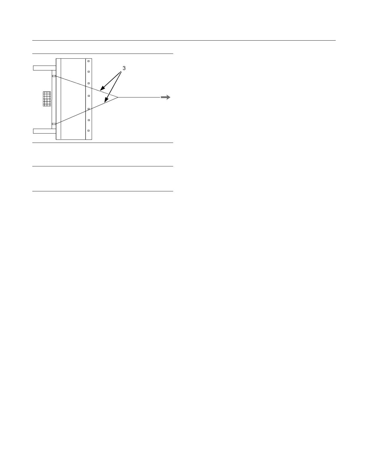
Two towing eyes (2) are located on the rear of the machine.
• The strength of the line should be at least 1.5 times
the gross weight of the machine.
• Provide shielding in order to protect the operator
if the line breaks.
• If a single line is used to pull the machine, then the
line must be a minimum of 3 m (10 ft). If two lines
are used to pull the machine, then each line must
be a minimum of 1.5 m (5.0 ft).
• Do not exceed a maximum pull angle of 20 degrees
in any direction.
g02623118
Illustration 90
Two towing eyes (1) are located on the front of the machine.
• Attach the line to the towing eyes. Two towing eyes
(1) are located on the front of the machine and
two towing eyes (2) are located on the rear of the
machine. Do not attach the line to any other point
on the machine.
NOTICE
Do not attach the line to only one towing eye when
you are retrieving the machine. Use both towing
eyes. Damage to the machine may occur.
110
SEBU8407-06
Operation Section
Towing Information
g01019066
Illustration 92
Each of the lines (3) must be a minimum of 1.5 m (5.0 ft).
NOTICE
Do not drag the machine for long distances. Damage
to the tracks or the tires may occur.
SEBU8407-06
111
Operation Section
Engine Starting (Alternate Methods)
Engine Starting (Alternate
NOTICE
Methods)
To prevent damage to engine bearings and to elec-
trical circuits when you jump start a machine, do not
allow the stalled machine to touch the machine that is
i02417424
used as the electrical source.
Engine Starting with Jump
Severely discharged maintenance free batteries do
Start Cables
not fully recharge from the alternator after jump start-
ing. The batteries must be charged to proper voltage
SMCS Code: 1000; 1401; 7000
with a battery charger. Many batteries thought to be
unusable are still rechargeable.
Use only equal voltage for starting. Check the battery
and starter voltage rating of your machine. Use only
Batteries give off flammable fumes that can ex-
the same voltage for jump starting. Use of a welder
plode resulting in personal injury.
or higher voltage damages the electrical system. This
machine has a 12 volt starting system. Use only the
Prevent sparks near the batteries. They could
same voltage for jump starting.
cause vapors to explode. Do not allow the jump
start cable ends to contact each other or the
Refer to Special Instruction, SEHS7633, “Battery Test
machine.
Procedure” available from your Caterpillar dealer, for
complete testing and charging information.
Do not smoke when checking battery electrolyte
levels.
1. Engage the parking brake. Lower the work tools
Electrolyte is an acid and can cause personal in-
to the ground.
jury if it contacts skin or eyes.
Reference: Refer to Operation and Maintenance
Always wear eye protection when starting a ma-
Manual, “Equipment Lowering with Engine
chine with jump start cables.
Stopped”.
Improper jump start procedures can cause an ex-
2. Move all hydraulic controls to the NEUTRAL
plosion resulting in personal injury.
position.
Always connect the positive (+) to positive (+) and
3. Turn the engine start switch key to the OFF
the negative (-) to negative (-).
position and turn all accessory switches to the
OFF position.
Jump start only with an energy source with the
same voltage as the stalled machine.
4. Move the machine that is being used as an
electrical source near the stalled machine so that
Turn off all lights and accessories on the stalled
the jump start cables reach the stalled machine.
machine. Otherwise, they will operate when the
Do not allow the machines to contact each
energy source is connected.
other.
5. Stop the engine of the machine that is being
used as an electrical source. If you are using
an auxiliary power source, turn off the charging
system.
6. Ensure that the battery in the stalled machine is
not frozen.
112
SEBU8407-06
Operation Section
Engine Starting (Alternate Methods)
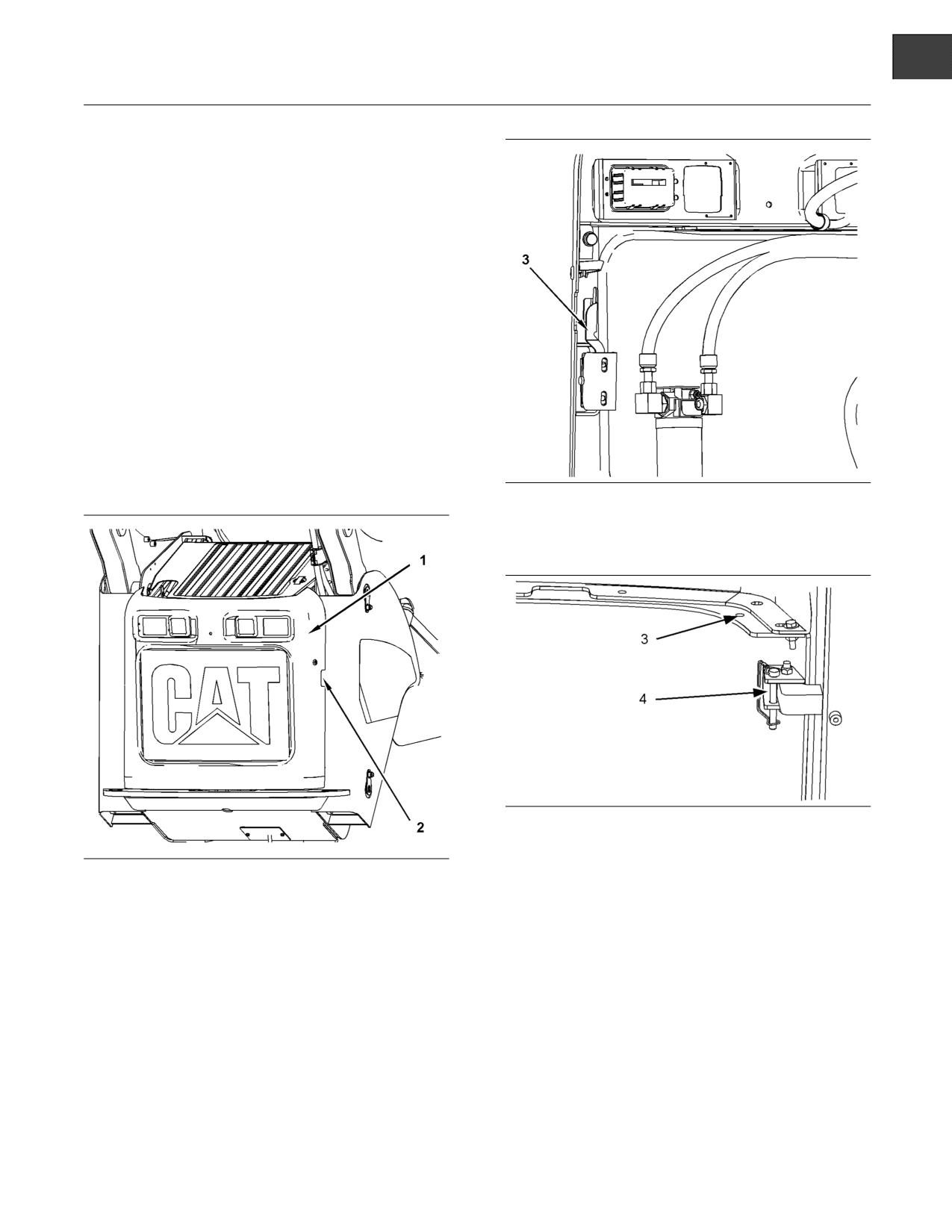
10. Connect the other negative end of the jump start
cable to the lifting eye on the engine of the stalled
machine. Do not connect the jump start cable
to the battery post. Do not allow the jump start
cables to contact the battery cables, the fuel
lines, the hydraulic lines, or any moving parts.
11. Start the engine of the machine that is being used
as an electrical source or energize the charging
system on the auxiliary power source.
12. Wait at least two minutes before you attempt
to start the stalled machine. This will allow the
battery in the stalled machine to partially charge.
13. Attempt to start the stalled engine.
Reference: For the correct starting procedure,
refer to Operation and Maintenance Manual,
“Engine Starting”.
g01210181
14. After the stalled engine starts, disconnect the
Illustration 93
negative jump start cable from the stalled machine.
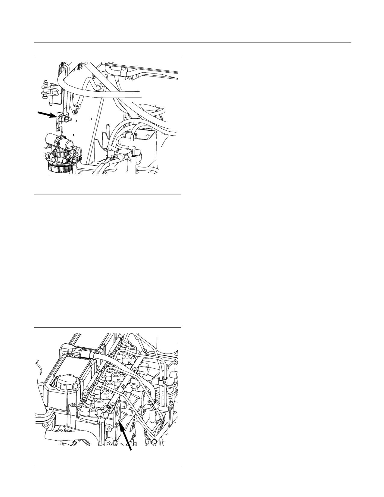
The jump start post on the left side of the engine compartment
is shown without the red cover.
15. Disconnect the negative jump start cable from the
negative terminal of the electrical source.
7. Connect the positive jump start cable to the
positive cable terminal that is provided in the
16. Disconnect the positive jump start cable from the
engine compartment of the stalled machine.
positive terminal of the electrical source.
Do not allow the positive cable clamps to contact
17. Disconnect the positive jump start cable from the
any metal except for the terminals.
positive terminal of the stalled machine.
8. Connect the other positive end of the jump start
18. Conclude the failure analysis on the starting
cable to the positive cable terminal of the electrical
system of the stalled machine and/or on the
source.
charging system of the stalled machine. Check
the machine while the engine is running and the
9. Connect one negative end of the jump start cable
charging system is in operation.
to the negative cable terminal of the electrical
source.
g01266722
Illustration 94
SEBU8407-06
113
Maintenance Section
Maintenance Access
Maintenance Section
Maintenance Access
i02417430
Access Doors and Covers
SMCS Code: 7273-572; 7273-573
Engine Access Door
Note: A pinch point exists between the top of the
engine access door and the radiator guard. Keep
hands away from this area when you close the
engine access door.
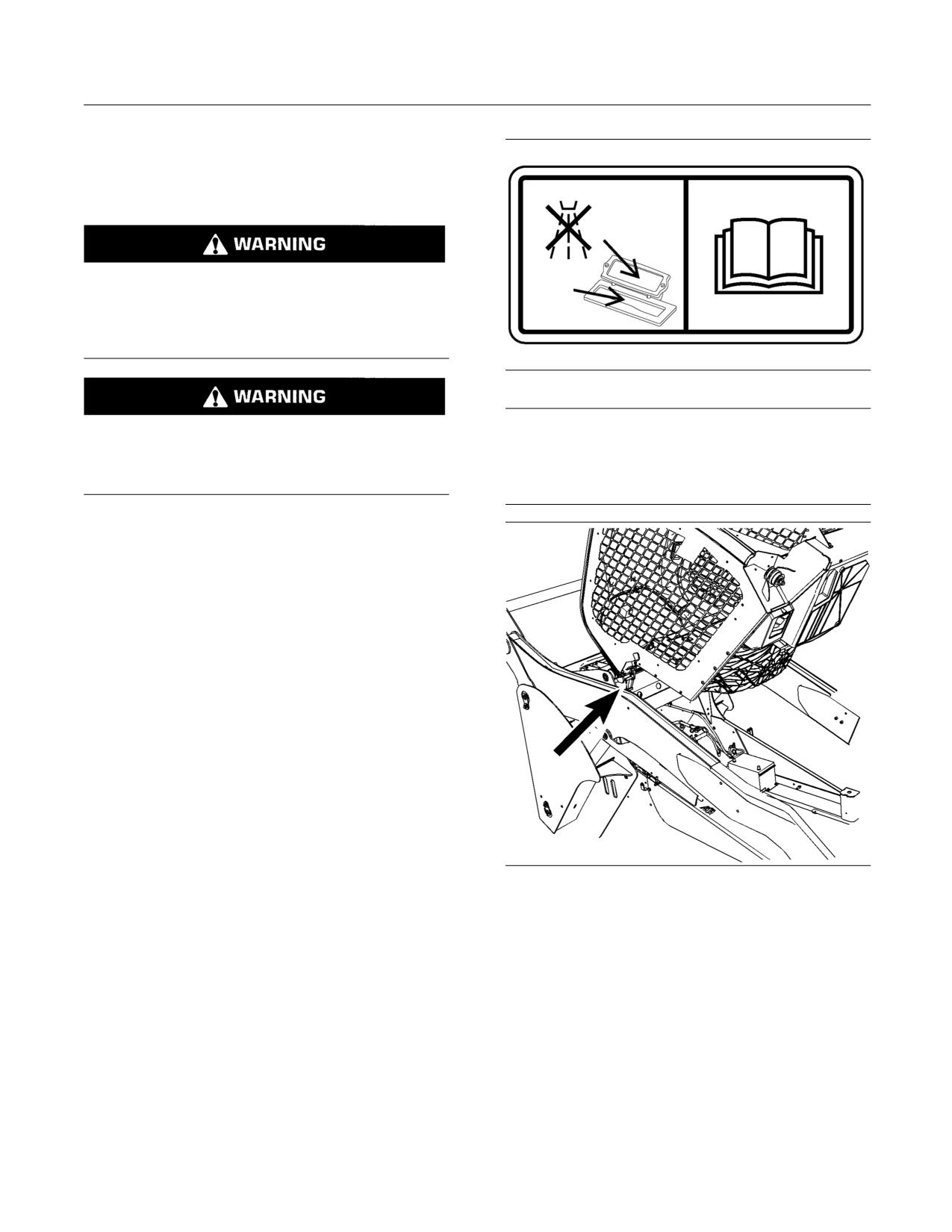
The engine access door is located on the back of
the machine.
g01210161
Illustration 96
1. Pull the release lever (3) in order to open the
engine access door (1).
g01019162
Illustration 97
2. Move the retaining pin from the stored position
g01210159
Illustration 95
(3) and put the retaining pin in the locked position
(4). This will prevent the engine access door from
(1) Engine Access Door
(2) Access for Release Lever
closing inadvertently.
3. In order to close the engine access door, put the
retaining pin in the stored position.
4. Close the engine access door. Ensure that the
latch is engaged.
114
SEBU8407-06
Maintenance Section
Maintenance Access
i02417435
Cab Tilting
SMCS Code: 7301-506; 7301-509
Do not go beneath cab unless cab is empty and
support lever is engaged.
Failure to follow the instructions or heed the warn-
ings could result in injury or death.
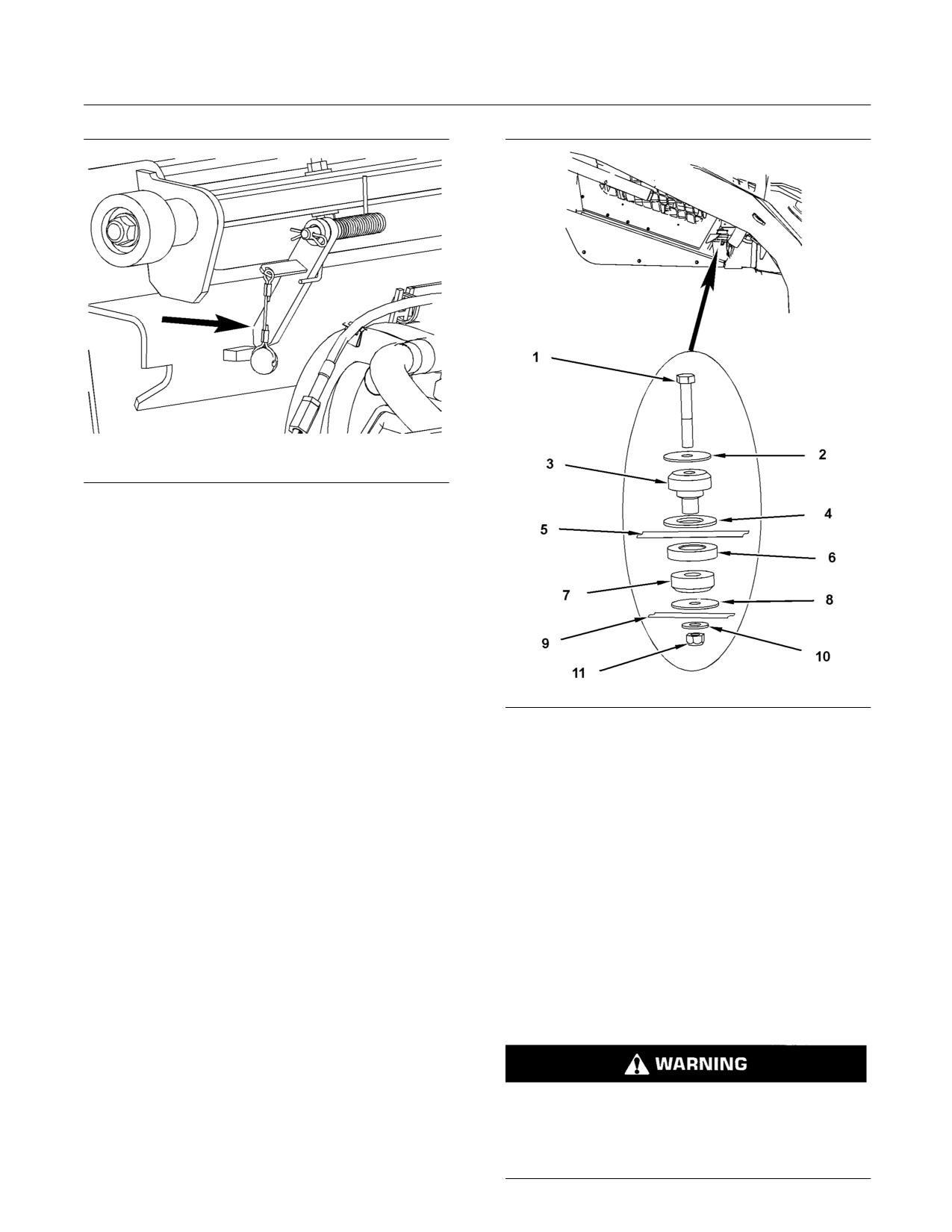
g01270620
Illustration 98
NOTICE
Do not tilt the cab using an open door. The door
Do not spray water or cleaning fluids into the venti-
must be closed and latched when lifting the cab.
lation ducts. Cover the opening in order to prevent
The door may become dislodged from its hinges
foreign material or fluid from entering the ventilation
and may cause serious personal injury or death.
ducts.
Tilting the Cab Upward
1. Park the machine on level ground.
Note: Empty the water tank (if equipped) before you
tilt the cab.
2. Lower the loader arms fully. If you tilt the cab
upward with the loader lift arms in the RAISED
position, you must engage the brace for the loader
lift arms. See Operation and Maintenance Manual,
“Loader Lift Arm Brace Operation” for the process
for engaging the brace for the loader lift arms.
3. Turn the engine start switch key to the OFF
position.
4. Remove the two front bolts for the ROPS. There is
one bolt on each side of the cab under the lift arm.
5. Close the cab door and ensure that the door is
g01210136
Illustration 99
latched.
6. Tilt the cab upward. Stand on the ground when
you tilt the cab.
Note: More than one person may be needed to tilt
the cab.
SEBU8407-06
115
Maintenance Section
Maintenance Access
g01210140
Illustration 100
Cab support lever
7. The cab support lever is on the right side of the
machine. Make sure that the cab support lever is
in the ENGAGED position.
Note: If water or other fluid is used, cover the
ventilation ducts with plastic.
Tilting the Cab Downward
Note: More than one person may be needed to tilt
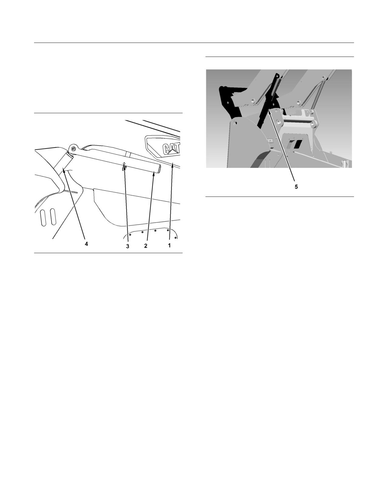
g01271548
Illustration 101
the cab.
(1) Bolt
(2) Washer
1. Remove the cover from the ventilation ducts.
(3) Rubber mount - top half
(4) Washer
2. Ensure that all persons are not under the cab.
(5) ROPS structure
Remove all of the tools and unsecured items that
(6) Spacer
(7) Rubber mount - bottom half
are underneath the cab.
(8) Washer
(9) Frame
3. Tilt the cab upward. Move the cab support lever to
(10) Spacer
the DISENGAGED position.
(11) Locknut
4. Tilt the cab downward.
i02417448
5. Install the bolts for the ROPS. Torque the bolts to
Loader Lift Arm Brace
125 ± 10 N·m (92 ± 7 lb ft).
Operation
SMCS Code: 6119-011-AB; 6119-012-AB
Loader lift arm brace must be in place when work-
ing under raised lift arms.
Failure to follow the instructions or heed the warn-
ings could result in injury or death.
116
SEBU8407-06
Maintenance Section
Maintenance Access
Engage the Lift Arm Brace
1. Empty the work tool. Remove the work tool. Park
the machine on level ground. Lower lift arms to
the ground.
2. Remain in the seat with the seat belt fastened until
the brace is installed.
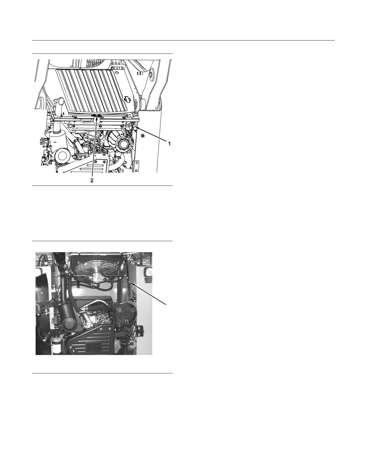
g01275092
Illustration 103
(5) Lift arm brace in the locked position
7. Stop the engine. Exit the machine.
Disengage the Lift Arm Brace
g01275448
1. Enter the machine. Fasten the seat belt. Lower
Illustration 102
the armrests and remain in the seat until the brace
(1) Lift arm
is in the stored position.
(2) Lift arm brace
(3) Retaining pin
(4) Lift cylinder
2. Start the engine.
3. A second person must remove the brace(2) from
3. Slowly raise the lift arms until the brace is free. A
the storage position. Remove the retaining pin(3)
second person must remove the retaining pin.
and allow the lift arm brace to lower.
4. Slowly lower the lift arms.
4. Raise the lift arms to the maximum height.
5. A second person must return the brace to the
5. The second person should then swing the lift arm
storage position. Secure the brace with the
brace into the locked position on the lift cylinder.
retaining pin.
Secure the brace with the retaining pin.
6. Slowly lower the lift arms to the ground.
6. Lower the lift arms against the brace.
i02417452
Radiator Tilting
SMCS Code: 1353-506; 1353-509
1. Open the engine access door. Refer to Operation
and Maintenance Manual, “Access Doors and
Covers”.
SEBU8407-06
117
Maintenance Section
Maintenance Access
6. Close the engine access door.
Tilting the Radiator Guard
1. Open the engine access door. Refer to Operation
and Maintenance Manual, “Access Doors and
Covers”.
2. Remove the retaining pin (2) for the radiator
guard. Tilt the radiator guard upward.
3. In order to tilt the radiator guard downward,
pull down on the radiator guard and install the
retaining pin.
g01209515
Illustration 104
(1) Radiator latch
(2) Retaining pin for the radiator guard
2. The release lever for the radiator latch is located
on the right side of the radiator. Push the release
lever for the radiator latch. Tilt the radiator upward.
g01209517
Illustration 105
3. The strut lock is located on the right side of the
engine compartment. Make sure that the strut lock
is in the LOCKED position.
4. In order to tilt the radiator downward, push the
lock on the strut and release the lock.
5. Tilt the radiator downward. Make sure that the
radiator is in the LOCKED position.
118
SEBU8407-06
Maintenance Section
Lubricant Viscosities and Refill Capacities
Machines that are operated continuously should
Lubricant Viscosities and
use oils that have the higher oil viscosity in the final
Refill Capacities
drives and in the differentials. The oils that have the
higher oil viscosity will maintain the highest possible
oil film thickness. Refer to “General Information for
i04777230
Lubricants” article, “Lubricant Viscosities” tables, and
any associated footnotes. Consult your Cat dealer if
Lubricant Viscosities
additional information is needed.
SMCS Code: 7581
NOTICE
Not following the recommendations found in this man-
General Information for Lubricants
ual can lead to reduced performance and compart-
ment failure.
When you are operating the machine in temperatures
below -20°C (-4°F), refer to Special Publication,
SEBU5898, “Cold Weather Recommendations”. This
Engine Oil
publication is available from your Cat dealer.
Cat oils have been developed and tested in order to
For cold-weather applications where transmission
provide the full performance and life that has been
oil SAE 0W-20 is recommended, Cat Cold Weather
designed and built into Cat engines.
TDTO is recommended.
Cat DEO-ULS multigrade and Cat DEO multigrade
Caterpillar has determined that Medium Wheel
oils are formulated with the correct amounts of
Loaders equipped with the High Ambient Cooling
detergents, dispersants, and alkalinity in order to
Attachment can operate with Cat HYDO Advanced
provide superior performance in Cat diesel engines
10 Hydraulic System Oil in ambient temperatures
where recommended for use.
from -20° C (-4° F) to 50° C (122° F).
Note: SAE 10W-30 is the preferred viscosity grade
Refer to the “Lubricant Information” section in the
for the 3116, 3126, C7, C-9, and C9 diesel engines
latest revision of the Special Publication, SEBU6250,
when the ambient temperature is between -18° C (0°
“Caterpillar Machine Fluids Recommendations” for a
F) and 40° C (104° F).
list of Cat engine oils and for detailed information. This
manual may be found on the Web at Safety.Cat.com.
The footnotes are a key part of the tables. Read ALL
footnotes that pertain to the machine compartment
in question.
Selecting the Viscosity
In order to select the proper oil for each machine
compartment, refer to the “Lubricant Viscosity for
Ambient Temperature” table. Use the oil type AND oil
viscosity for the specific compartment at the proper
ambient temperature.
The proper oil viscosity grade is determined by
the minimum ambient temperature (the air in the
immediate vicinity of the machine). Measure the
temperature when the machine is started and while
the machine is operated. In order to determine
the proper oil viscosity grade, refer to the “Min”
column in the table. This information reflects the
coldest ambient temperature condition for starting
a cold machine and for operating a cold machine.
Refer to the “Max” column in the table for operating
the machine at the highest temperature that is
anticipated. Unless specified otherwise in the
“Lubricant Viscosities for Ambient Temperatures”
tables, use the highest oil viscosity that is allowed for
the ambient temperature.
SEBU8407-06
119
Maintenance Section
Lubricant Viscosities and Refill Capacities
Table 24
Engine Crankcase
°C
°F
Oil Type and Performance
Compartment or System
Oil Viscosities
Requirements
Min
Max
Min
Max
Cat DEO-ULS Cold Weather
SAE 0W-40
-40
40
-40
104
Cat DEO-ULS
SAE 10W-30
-18
40
0
104
Engine Crankcase
Cat DEO
Cat DEO-ULS
SAE 15W-40
-9.5
50
15
122
Cat DEO
When fuels of sulfur level of 0.1 percent (1000 ppm)
• Cat DEO-ULS SYN
or higher are used, Cat DEO-ULS may be used if
S·O·S oil analysis program is followed. Base the oil
• Cat DEO SYN
change interval on the oil analysis.
• Cat DEO-ULS Cold Weather
Hydraulic Systems
Refer to the “Lubricant Information” section in the
latest revision of the Special Publication, SEBU6250,
“Caterpillar Machine Fluids Recommendations” for
detailed information. This manual may be found on
the Web at Safety.Cat.com.
The following are the preferred oils for use in most
Cat machine hydraulic systems:
• Cat HYDO Advanced 10 SAE 10W
• Cat HYDO Advanced 30 SAE 30W
• Cat BIO HYDO Advanced
Cat HYDO Advanced fluids have a 50% increase
in the standard oil drain interval for machine
hydraulic systems (3000 hours versus 2000 hours)
over second and third choice oils when you follow the
maintenance interval schedule for oil filter changes
and for oil sampling that is stated in the Operation
and Maintenance Manual for your particular machine.
6000 hour oil drain intervals are possible when using
S·O·S Services oil analysis. Consult your Cat dealer
for details. When switching to Cat HYDO Advanced
fluids, cross contamination with the previous oil
should be kept to less than 10%.
Second choice oils are listed below.
• Cat MTO
• Cat DEO
• Cat DEO-ULS
• Cat TDTO
• Cat TDTO Cold Weather
• Cat TDTO-TMS

120
SEBU8407-06
Maintenance Section
Lubricant Viscosities and Refill Capacities
Table 25
Hydraulic System
°C
°F
Oil Type and Performance
Compartment or System
Oil Viscosities
Requirements
Min
Max
Min
Max
Cat HYDO Advanced 10
SAE 10W
-20
40
-4
104
Cat TDTO
Cat HYDO Advanced 30
SAE 30
0
50
32
122
Cat TDTO
“ISO 46”
Cat BIO HYDO Advanced
-30
45
-22
113
Multi-Grade
Cat MTO
Hydraulic System
Cat DEO-ULS
SAE10W-30
-20
40
-4
104
Cat DEO
Cat DEO-ULS
SAE15W-40
-15
50
5
122
Cat DEO
Cat TDTO-TMS
Multi-Grade
-15
50
5
122
Cat DEO-ULS Cold Weather
SAE0W-40
-40
40
-40
104
Cat TDTO Cold Weather
SAE 0W-20
-40
40
-40
104
Drive Train Components
Refer to the “Lubricant Information” section in the
latest revision of the Special Publication, SEBU6250,
“Caterpillar Machine Fluids Recommendations” for
detailed information. This manual may be found on
the Web at Safety.Cat.com.
When you are operating the machine in temperatures
below -20°C (-4°F), refer to Special Publication,
SEBU5898, “Cold Weather Recommendations”. This
publication is available from your Cat dealer.
Table 26
Drive Train Components
Oil Type and
°C
°F
Compartment or
Performance
Oil Viscosities
System
Requirements
Min
Max
Min
Max
Cat DEO-ULS Cold
SAE 0W-40
-40
40
-40
104
Weather
Track Idlers and Track
Cat DEO-ULS
SAE 10W-30
-18
40
0
104
Rollers
Cat DEO
Cat DEO-ULS
SAE 15W-40
-9.5
50
15
122
Cat DEO
Caterpillar
Final Drive
SAE 75W-140
-30
45
-22
113
Synthetic GO(1)(2)
(1) Cat Synthetic GO is the preferred oil for the final drive. If Cat Synthetic GO is not available, Cat GO, or API GL-5 grade oil may be substituted.
(2) Cat GO (Gear Oil) is available in SAE 80W-90 and SAE 85W-140 viscosity grades.

SEBU8407-06
121
Maintenance Section
Lubricant Viscosities and Refill Capacities
Special Lubricants
Grease
In order to use a non-Cat grease, the supplier must
certify that the lubricant is compatible with Cat
grease.
Each pin joint should be flushed with the new grease.
Ensure that all old grease is removed. Failure to meet
this requirement may lead to failure of a pin joint.
Table 27
Recommended Grease
°C
°F
Compartment or System
GreaseType
NLGI Grade
Min
Max
Min
Max
Cat Advanced 3Moly
NLGI Grade 2
-20
40
-4
104
NLGI Grade 2
-30
50
-22
122
Cat Ultra 5Moly
NLGI Grade 1
-35
40
-31
104
External Lubrication Points
NLGI Grade 0
-40
35
-40
95
Cat Arctic Platinum
NLGI Grade 0
-50
20
-58
68
Cat Desert Gold
NLGI Grade 2
-20
60
-4
140
External Lubrication Points,
Track Roller Frame Recoil
Cat Advanced 3Moly
NLGI Grade 2
-20
40
-4
104
Spring
Diesel Fuel Recommendations
• Lower fuel economy
Diesel fuel must meet “Caterpillar Specification
• Shorten the time period between oil drain intervals
for Distillate Fuel” and the latest versions of
(more frequent oil drain intervals)
“ASTM D975” or “EN 590” in order to ensure
optimum engine performance. Refer to Special
• Increase overall operating costs
Publication, SEBU6250, “Caterpillar Machine Fluids
Recommendations” for the latest fuel information and
• Negatively impact engine emissions
for Cat fuel specification. This manual may be found
on the Web at Safety.Cat.com.
Failures that result from the use of improper fuels
are not Caterpillar factory defects. Therefore the
The preferred fuels are distillate fuels. These
cost of repairs would not be covered by a Caterpillar
fuels are commonly called diesel fuel, furnace oil,
warranty.
gas oil, or kerosene. These fuels must meet the
“Caterpillar Specification for Distillate Diesel Fuel
Caterpillar does not require the use of ULSD in off
for Off-Highway Diesel Engines”. Diesel Fuels that
road and machine applications that are not Tier
meet the Caterpillar specification will help provide
4/Stage IIIB certified engines. ULSD is not required
maximum engine service life and performance.
in engines that are not equipped with after treatment
devices.
Misfueling with fuels of high sulfur level can have
the following negative effects:
Follow operating instructions and fuel tank inlet
labels, if available, in order to ensure that the correct
• Reduce engine efficiency and durability
fuels are used.
• Increase the wear
Refer to Special Publication, SEBU6250, “Caterpillar
Machine Fluids Recommendations” for more details
• Increase the corrosion
about fuels and lubricants. This manual may be found
on the Web at Safety.Cat.com.
• Increase the deposits
122
SEBU8407-06
Maintenance Section
Lubricant Viscosities and Refill Capacities
Fuel Additives
Preferred - Cat ELC (Extended Life Coolant)
Cat Diesel Fuel Conditioner and Cat Fuel System
Acceptable - Cat DEAC (Diesel Engine
Cleaner are available for use when needed. These
Antifreeze/Coolant)
products are applicable to diesel and biodiesel fuels.
Consult your Cat dealer for availability.
NOTICE
Never use water alone as a coolant. Water alone is
Biodiesel
corrosive at engine operating temperatures. In addi-
tion, water alone does not provide adequate protec-
Biodiesel is a fuel that can be made from various
tion against boiling or freezing.
renewable resources that include vegetable oils,
animal fat, and waste cooking oil. Soybean oil and
rapeseed oil are the primary vegetable oil sources.
i04113550
In order to use any of these oils or fats as fuel, the
oils or fats are chemically processed (esterified). The
Capacities (Refill)
water and contaminants are removed.
SMCS Code: 7560
U.S. distillate diesel fuel specification “ASTM
Table 28
D975-09a” includes up to B5 (5 percent) biodiesel.
Currently, any diesel fuel in the U.S. may contain up
Approximate Refill Capacities
to B5 biodiesel fuel.
Compartment
US
Imperial
Liters
or System
Gallons
Gallons
European distillate diesel fuel specification “EN 590”
includes up to B5 (5 percent) and in some regions up
Engine Crankcase
10(1)
2.6(2)
2.2
to B7 (7 percent) biodiesel. Any diesel fuel in Europe
3044
may contain up to B5 or in some regions up to B7
Hydraulic Tank
39
10.3
8.6
biodiesel fuel.
Cooling System
13.9
3.7
3.1
Note: Up to B20 biodiesel blend level is acceptable
Fuel Tank
97.5
25.8
21.4
for use in Cat machine engines.
Final Drive
1.0
0.26
0.22
When biodiesel fuel is used, certain guidelines must
Window Washer
be followed. Biodiesel fuel can influence the engine
1.7
0.45
0.37
Fluid
oil, aftertreatment devices, non-metallic, fuel system
components, and others. Biodiesel fuel has limited
(1) The amount includes 1L in the filter.
(2) The amount includes 0.26G in the filter.
storage life and has limited oxidation stability. Follow
the guidelines and requirements for engines that
Table 29
are seasonally operated and for standby power
generation engines.
Track Roller Frame Approximate Refill Capacities
Compartment or System
Milliliters
In order to reduce the risks associated with the use of
biodiesel, the final biodiesel blend and the biodiesel
Track Roller
240 ± 12 ml
fuel used must meet specific blending requirements.
Idler - Single Flange
349 ± 15 ml
All the guidelines and requirements are provided in
Idler - Dual Flange
354 ± 15 ml
the latest revision of Special Publication, SEBU6250,
“Caterpillar Machine Fluids Recommendations”. This
manual may be found on the Web at Safety.Cat.com.
i04311449
Coolant Information
S·O·S Information
The information provided in this “Coolant
SMCS Code: 1000; 7000; 7542-008
Recommendation” section should be used with the
“Lubricants Information” provided in the latest revision
S·O·S Services is a highly recommended process for
of Special Publication, SEBU6250, “Caterpillar
Cat customers to use in order to minimize owning
Machine Fluids Recommendations”. This manual
and operating cost. Customers provide oil samples,
may be found on the Web at Safety.Cat.com.
coolant samples, and other machine information.
The dealer uses the data in order to provide the
The following two types of coolants may be used in
customer with recommendations for management of
Cat diesel engines:
the equipment. In addition, S·O·S Services can help
determine the cause of an existing product problem.
SEBU8407-06
123
Maintenance Section
Lubricant Viscosities and Refill Capacities
Refer to Special Publication, SEBU6250, “Caterpillar
Machine Fluid Recommendations” for detailed
information concerning S·O·S Services.
Refer to the Operation and Maintenance Manual,
“Maintenance Interval Schedule” for a specific
sampling location and a service hour maintenance
interval.
Consult your Cat dealer for complete information and
assistance in establishing an S·O·S program for your
equipment.
124
SEBU8407-06
Maintenance Section
Maintenance Support
Maintenance Support
i02916513
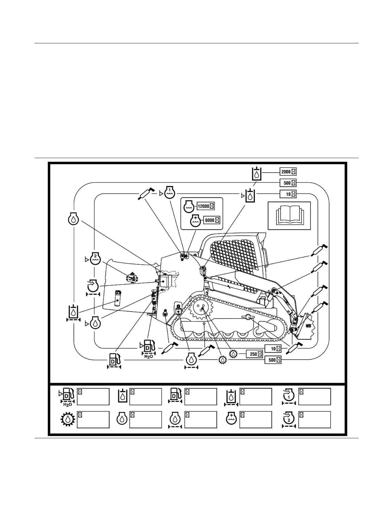
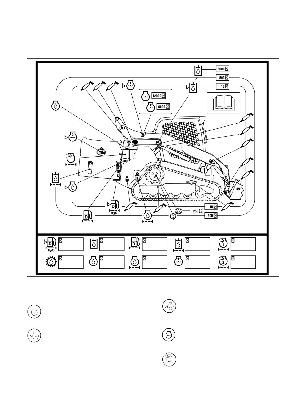
Service Interval Chart
SMCS Code: 7000
Refer to the following service interval charts
and service intervals for additional maintenance
information.
279C Service Interval Chart
g01450836
Illustration 106
SEBU8407-06
125
Maintenance Section
Maintenance Support
289C and 299C Service Interval
Chart
g01450838
Illustration 107
Service Intervals
Coolant level (reservoir) - Check the
Coolant additive - Add the extender to
coolant level in the coolant reservoir after
the extended life coolant after every 6000
every ten service hours or at the end of
service hours or every 3 years.
each day.
Coolant level (radiator) - Check the
Cooling system coolant - Change the
coolant level in the radiator at the sight
ELC (Extended Life Coolant) after every
gauge after every ten service hours or at
12,000 hours or every 6 years.
the end of each day.
Engine air filter primary element - Clean
the primary air filter element or replace the
primary air filter element. The alert indicator
for the air filter indicates when servicing is necessary.

126
SEBU8407-06
Maintenance Section
Maintenance Support
i03636245
Engine air filter secondary element -
Welding on Machines and
Replace the secondary air filter element
with every third change of the primary
Engines with Electronic
air filter element or replace the secondary air filter
element when it is necessary.
Controls
SMCS Code: 1000; 7000
Engine oil level check - Check the engine
oil level after every ten service hours or at
Do not weld on any protective structure. If it is
the end of each day.
necessary to repair a protective structure, contact
your Caterpillar dealer.
Engine oil - Change the engine oil after
every 500 service hours or every year.
Proper welding procedures are necessary in order to
avoid damage to the electronic controls and to the
bearings. When possible, remove the component
Engine oil filter - Change the filter after
that must be welded from the machine or the engine
every 500 service hours or every three
and then weld the component. If you must weld near
months.
an electronic control on the machine or the engine,
temporarily remove the electronic control in order to
prevent heat related damage. The following steps
Final Drive oil - Check the final drive oil
should be followed in order to weld on a machine or
after every 250 service hours. Change the
an engine with electronic controls.
final drive oil after the initial 250 service
hours. Change the final drive oil after every 500
1. Turn off the engine. Place the engine start switch
service hours.
in the OFF position.
Fuel system water separator - Drain
2. If equipped, turn the battery disconnect switch to
the water separator after every ten service
the OFF position. If there is no battery disconnect
hours or at the end of each day.
switch, remove the negative battery cable at the
battery.
Fuel System Filter/Water Separator
Element - Replace the filter after every
NOTICE
500 service hours or every three months.
Do NOT use electrical components (ECM or sensors)
or electronic component grounding points for ground-
Grease zerk - Lubricate the designated
ing the welder.
locations after every ten service hours or
at the end of each day.
3. Clamp the ground cable from the welder to the
component that will be welded. Place the clamp
Hydraulic oil filter - Change the filter
as close as possible to the weld. Make sure that
after every 500 service hours or every three
the electrical path from the ground cable to the
months.
component does not go through any bearing. Use
this procedure in order to reduce the possibility of
damage to the following components:
Hydraulic oil level check - Check the
hydraulic oil level at the sight gauge after
every ten service hours or at the end of
• Bearings of the drive train
each day.
• Hydraulic components
Hydraulic oil - Change the hydraulic oil
• Electrical components
after every 2000 service hours or every
year.
• Other components of the machine
4. Protect any wiring harnesses and components
from the debris and the spatter which is created
from welding.
5. Use standard welding procedures in order to weld
the materials together.
SEBU8407-06
127
Maintenance Section
Maintenance Interval Schedule
i04776466
Lower Machine Frame - Clean
163
Oil Filter - Inspect
164
Maintenance Interval Schedule
Radiator Core - Clean
165
Sprocket - Inspect
168
SMCS Code: 7000
Track - Remove/Replace
171
Window Washer Reservoir - Fill
172
Ensure that all safety information, warnings, and
Window Wiper - Inspect/Replace
173
instructions are read and understood before any
Windows - Clean
173
operation or any maintenance procedures are
performed.
Every 10 Service Hours or Daily
The user is responsible for the performance of
Air Cleaner Dust Valve - Clean/Inspect
130
maintenance. All adjustments, the use of proper
Axle Bearings - Lubricate
132
lubricants, fluids, filters, and the replacement of
Backup Alarm - Test
132
components due to normal wear and aging are
Cooling System Level - Check
143
included. Failure to adhere to proper maintenance
Engine Oil Level - Check
148
intervals and procedures may result in diminished
Equipment Lowering Control Valve - Check
150
performance of the product and/or accelerated wear
Fuel System Primary Filter (Water Separator) -
of components.
Drain
152
Hydraulic System Oil Level - Check
161
Use mileage, fuel consumption, service hours, or
Lift Arm and Cylinder Linkage - Lubricate
163
calendar time, WHICH EVER OCCURS FIRST,
Quick Coupler - Clean/Inspect
165
in order to determine the maintenance intervals.
Seat Belt - Inspect
167
Products that operate in severe operating conditions
Tilt Cylinder Bearings and Bucket Linkage Bearings -
may require more frequent maintenance. Refer to the
Lubricate
169
maintenance procedure for any other exceptions that
Track - Inspect/Adjust
169
may change the maintenance intervals.
Track Roller and Idler - Inspect/Replace
172
Work Tool - Lubricate
174
Note: The aftertreatment system can be expected
Work Tool Mounting Bracket - Inspect
176
to function properly for the useful life of the
engine (emissions durability period), as defined by
Initial 250 Service Hours
regulation. All prescribed maintenance requirements
must be followed.
Final Drive Oil - Change
151
Note: Before each consecutive interval is performed,
Every 250 Service Hours
all maintenance from the previous interval must be
Final Drive Oil Level - Check
151
performed.
Note: If Cat HYDO Advanced hydraulic oils are used,
Every 250 Service Hours or Monthly
the hydraulic oil change interval is extended to 3000
Belts - Inspect/Adjust/Replace
133
hours. S·O·S services may extend the oil change
even longer. Consult your Cat dealer for details.
Every 500 Service Hours
When Required
Cooling System Coolant Sample (Level 1) -
Obtain
141
Aftercooler Core - Inspect/Clean
129
Final Drive Oil - Change
151
Aftercooler Intake Screen - Clean
130
Hydraulic System Oil Sample - Obtain
162
Air Conditioner Condenser - Clean
131
Battery or Battery Cable - Inspect/Replace
132
Every 500 Service Hours or 6 Months
Blade Frame - Adjust
135
Bucket Cutting Edges - Inspect/Replace
136
Fuel System Primary Filter (Water Separator)
Bucket Tips - Inspect/Replace
136
Element - Replace
153
Cab Air Filter - Clean/Replace
137
Hydraulic System Oil Filter - Replace
160
Cab Interior - Clean
137
Engine Air Filter Primary Element - Clean/
Every 500 Service Hours or 1 Year
Replace
144
Engine Air Filter Secondary Element - Replace .. 146
Engine Oil and Filter - Change
148
Engine Compartment - Inspect/Clean
147
Hydraulic Tank Breather - Replace
162
Fuel System Priming Pump - Operate
154
Fuel Tank Cap - Clean
154
Every 1000 Service Hours
Fuel Tank Water and Sediment - Drain
154
Fuses - Replace
155
Engine Valve Lash - Check
150
128
SEBU8407-06
Maintenance Section
Maintenance Interval Schedule
Every 1000 Service Hours or 6 Months
Rollover Protective Structure (ROPS) and Falling
Object Protective Structure (FOPS) - Inspect ...
167
Every 2000 Service Hours
Refrigerant Dryer - Replace
166
Every 2000 Service Hours or 1 Year
Fuel Injection Timing - Check
152
Hydraulic System Oil - Change
158
Every Year
Cooling System Coolant Sample (Level 2) -
Obtain
142
Every 3000 Service Hours or 2 Years
Cooling System Water Temperature Regulator -
Replace
143
Every 3 Years
Seat Belt - Replace
168
Every 6000 Service Hours or 3 Years
Cooling System Coolant Extender (ELC) - Add ..
140
Every 12 000 Service Hours or 6 Years
Cooling System Coolant (ELC) - Change
138
SEBU8407-06
129
Maintenance Section
Aftercooler Core - Inspect/Clean
i02555053
Inspect these items for good condition: welds,
mounting brackets, air lines, connections, clamps,
Aftercooler Core -
and seals. Make repairs, if necessary.
Inspect/Clean
Clean
SMCS Code: 1064-571; 1064-571-Z3
For air-to-air aftercoolers, use the same methods that
are used for cleaning radiators.
Inspect
Note: Adjust the frequency of inspection according to
the effects of the operating environment. Clean the
aftercooler core when you clean the radiator core.
Personal injury can result from air pressure.
The aftercooler is located behind the cab and in front
Personal injury can result without following prop-
of the engine.
er procedure. When using pressure air, wear a pro-
tective face shield and protective clothing.
Maximum air pressure at the nozzle must be less
than 205 kPa (30 psi) for cleaning purposes.
NOTICE
When you are using compressed air or high pressure
water to clean the radiator fins, ensure that the air or
water is directed parallel to the fins. If the compressed
air or high pressure water is not directed parallel to the
radiator fins, the radiator fins could be bent or dam-
aged.
Pressurized air is the preferred method for removing
loose debris. Hold the nozzle approximately 6 mm
(0.25 inch) away from the fins. Slowly move the air
nozzle in a direction that is parallel with the tubes.
The air nozzle should point in the opposite direction
of the flow of the fan. This will remove debris that is
between the tubes.
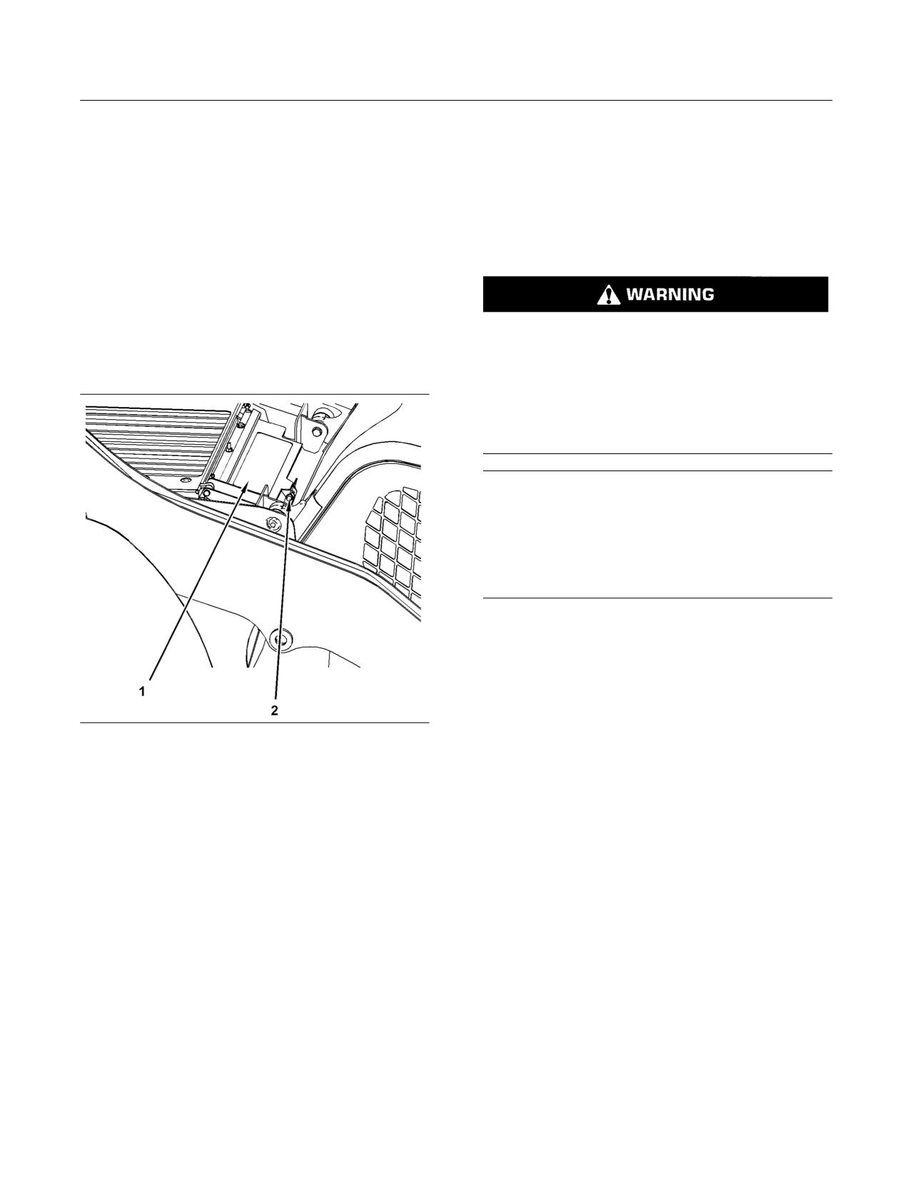
g01279112
Illustration 108
Pressurized water may also be used for cleaning.
1. Stop the engine.
The maximum water pressure for cleaning purposes
must be less than 275 kPa (40 psi). Use pressurized
2. Clean the grill before you access the aftercooler
water in order to soften mud.
core.
Use a degreaser and steam for removal of oil and
3. Remove the pin (2) that holds the grill (1) and lift
grease. Wash the core with detergent and hot water.
the grill.
Thoroughly rinse the core with clean water.
Note: If parts of the aftercooler system may appear
After cleaning, start the engine and accelerate the
to be damaged or if parts of the aftercooler system
engine to high idle rpm. This will help in the removal
are repaired, a leak test is highly recommended.
of debris and drying of the core. Stop the engine.
Consult your Caterpillar dealer for the most current
Use a light bulb behind the core in order to inspect
information about the aftercooler.
the core for cleanliness. Repeat the cleaning, if
necessary.
Inspect the fins and tubes of the aftercooler for
damage. Some fins and tubes may be worn from
Note: Adjust the frequency of cleaning according to
abrasive material that has passed through the
the effects of the operating environment. If there is an
aftercooler cores. Bent fins may be opened with a
extreme amount of debris, you may need to remove
“comb”.
the air conditioning condenser or the cover plate from
the fan housing for the aftercooler.
Close the grill and replace the retaining pin.
130
SEBU8407-06
Maintenance Section
Aftercooler Intake Screen - Clean
i02559029
Aftercooler Intake Screen -
Clean
SMCS Code: 1063-070-Z3
Personal injury can result from air pressure.
Personal injury can result without following prop-
er procedure. When using pressure air, wear a pro-
tective face shield and protective clothing.
Maximum air pressure at the nozzle must be less
than 205 kPa (30 psi) for cleaning purposes.
Note: Adjust the frequency of cleaning according to
the effects of the operating environment.
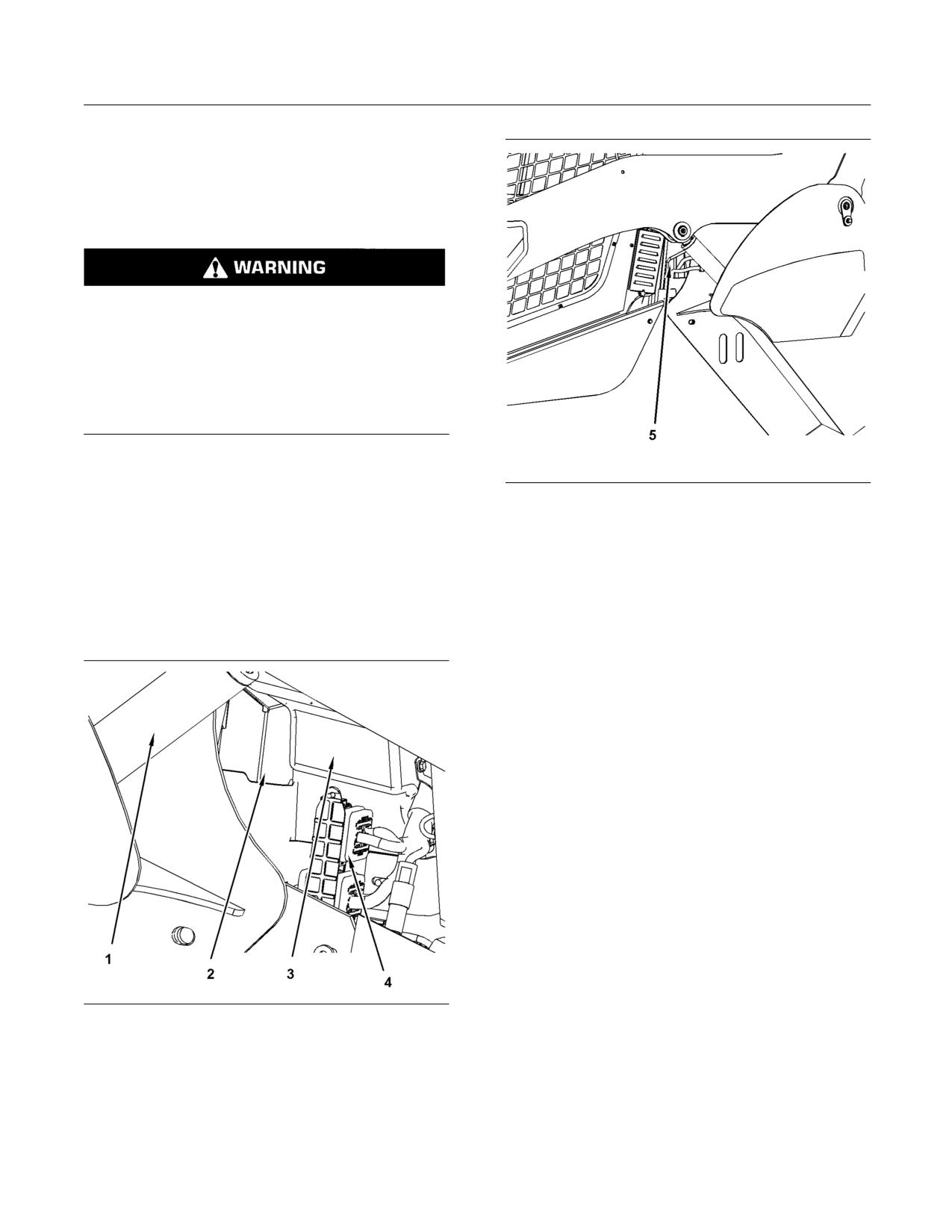
g01281018
Illustration 110
Note: Pressurized air is the preferred method for
(5) Air inlet screen
removing loose debris. Pressurized water may also
be used for cleaning. Use pressurized water in order
3. Access the screen from the left side of the
to soften mud. Clean the screen from both sides. The
machine. Hold the nozzle approximately 6 mm
maximum water pressure for cleaning purposes must
(0.25 inch) away from the screen.
be less than 275 kPa (40 psi).
4. If water is used to clean the screen, ensure that
1. Turn off the engine.
the screen is dry before the engine is started. If
necessary, use compressed air to dry the screen.
i02939506
Air Cleaner Dust Valve -
Clean/Inspect
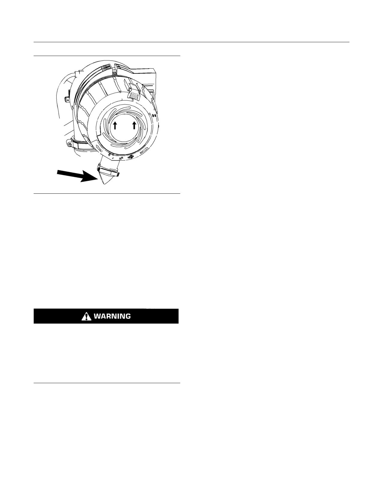
SMCS Code: 1051-571-VL
Service the air filter elements when the alert indicator
for air filter restriction lights. Refer to Operation
and Maintenance Manual, “Alert Indicators” for
information about the indicator.
1. Open the engine access door.
2. The air filter housing is located on the right side of
the engine compartment.
g01281019
Illustration 109
(1) Cylinder for the lift arm
(2) Air inlet screen
(3) Hydraulic tank
(4) Electrical connectors
2. Access the screen from the right side of the
machine. Hold the nozzle approximately 6 mm
(0.25 inch) away from the screen. Ensure that the
spray nozzle is past the electrical connections.
SEBU8407-06
131
Maintenance Section
Air Conditioner Condenser - Clean
• Damaged fins
• Buildup of debris
• Plugged areas
Remove any debris. Clean the condenser with low
pressure air or low pressure water. The maximum
water pressure for cleaning purposes must be less
than 275 kPa (40 psi).
272C, 297C, and 299C
The air conditioner condenser is attached to the side
of the fan housing for the aftercooler.
1. Remove the 3 bolts that retain the condenser to
the fan housing for the aftercooler.
2. Lift the core and remove the core from the
retaining lip.
g01280861
Illustration 111
3. Clean the condenser core in the opposite direction
3. Check the dust valve after every ten service hours
of the air flow.
or at the end of each day. Actuate the valve by
squeezing the lips of the valve in order to remove
4. Reinstall the core in reverse order.
any accumulated debris.
i02916544
Air Conditioner Condenser -
Clean
(If Equipped)
SMCS Code: 1805-070
Personal injury can result from air pressure.
Personal injury can result without following prop-
er procedure. When using pressure air, wear a pro-
tective face shield and protective clothing.
Maximum air pressure at the nozzle must be less
than 205 kPa (30 psi) for cleaning purposes.
246C, 256C, 262C, 277C, 287C,
279C, and 289C
The air conditioner condenser is located behind the
engine on the frame.
Open the engine access door.
Inspect the air conditioner condenser for the following
conditions:
132
SEBU8407-06
Maintenance Section
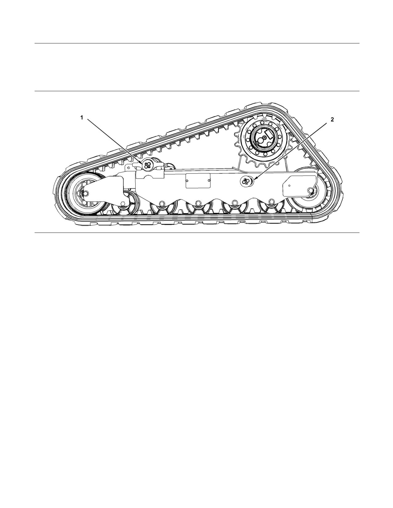
Axle Bearings - Lubricate
i02916524
Axle Bearings - Lubricate
SMCS Code: 3282-086-BD
g01451286
Illustration 112
(1) Front pivot
(2) Rear pivot
Apply lubricant to all grease fittings.
i03659214
Battery or Battery Cable -
Repeat the process for the opposite side of the
machine.
Inspect/Replace
SMCS Code: 1401-040; 1401-510; 1401-561;
i02580453
1402-040; 1402-510
Backup Alarm - Test
1. Turn the engine start switch to the OFF position.
SMCS Code: 7406-081
Turn all switches to the OFF position.
To prevent injury, make sure that no people are
2. The battery is located on the left side of the
working on the machine or near the machine. To
machine under the cab. Raise the cab. Refer to
prevent injury, keep the machine under control at all
Operation and Maintenance Manual, “Cab Tilting”
times.
for information on raising the cab.
1. Get into the operator's seat. Fasten the seat belt
3. Disconnect the negative battery cable at the
and pull the armrests downward.
battery.
2. Start the engine.
Note: Do not allow the disconnected battery cable to
contact the negative battery post.
3. Disengage the parking brake.
4. Disconnect the negative battery cable from the
4. Move the joystick control to the REVERSE
frame in order to inspect the cable.
position.
5. Disconnect the positive battery cable at the
The backup alarm should sound immediately.
battery.
The backup alarm should continue to sound until
the joystick control is returned to the NEUTRAL
6. Perform the necessary repairs. Replace the
position or to the FORWARD position.
cables or the battery, as needed.
7. Connect the positive battery cable at the battery.
SEBU8407-06
133
Maintenance Section
Belts - Inspect/Adjust/Replace
8. Connect the negative battery cable to the frame of
the machine.
9. Connect the negative battery cable at the battery.
10. Lower the cab. Refer to Operation and
Maintenance Manual, “Cab Tilting” for information
on lowering the cab.
Recycle the Battery
Always recycle a battery. Never discard a battery.
Always return used batteries to one of the following
locations:
• A battery supplier
• An authorized battery collection facility
• Recycling facility
g01209498
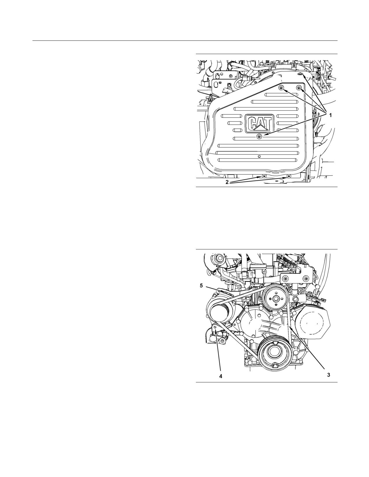
Illustration 113
i02715751
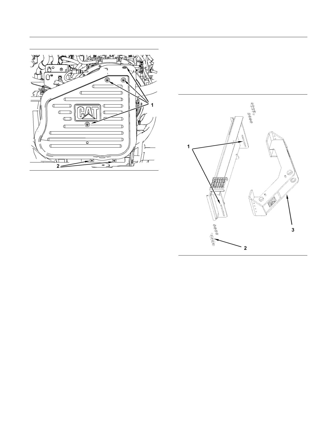
3. Remove the four bolts (1) on the top of the guard.
Loosen the two bolts (2) on the bottom of the
Belts - Inspect/Adjust/Replace
guard.
SMCS Code: 1357-025; 1357-040; 1357-510
4. Slide the guard upward from bottom bolts.
Remove the guard for the V-belt.
If a new belt is installed, check the belt adjustment
after 30 minutes of operation. A belt is considered to
be used after 30 minutes of operation.
Belts
1. Stop the engine in order to inspect the belt.
2. Open the engine access door. Refer to Operation
and Maintenance Manual, “Access Doors and
Covers”.
g01209499
Illustration 114
5. Inspect the condition of the belt (3) and the
adjustment of the belt. The belt should deflect
10 mm (0.39 inch) under a straight pull of 44 N
(10 lb). This measurement should be taken
between the alternator pulley and the crankshaft
pulley.
134
SEBU8407-06
Maintenance Section
Belts - Inspect/Adjust/Replace
Note: A 144-0235 Borroughs Belt Tension
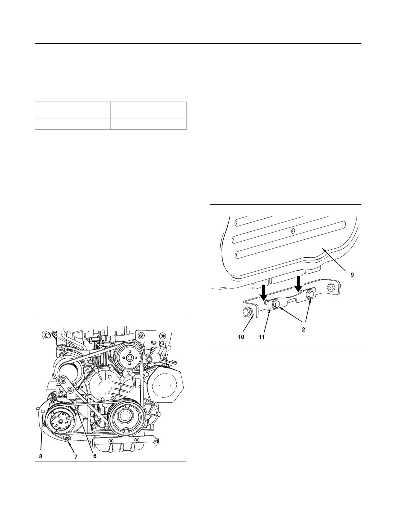
2. Loosen the mounting bolt (6) for the air conditioner
Gauge may be used to measure belt tension.
compressor. Loosen the adjusting locknut (7) for
This measurement should be taken between the
the air conditioner compressor.
alternator pulley and the crankshaft pulley. Refer to
the following table for belt tension.
3. Move the air conditioner compressor until the
correct tension is reached.
Table 30
Note: A hole (8) in the bracket has been provided in
Belt Tension
Belt Tension
Initial
Used
order to aid with the adjustment of the tension.
534 ± 22 N (120 ± 5 lb)
400 ± 44 N (90 ± 10 lb)
4. Tighten the adjusting locknut. Tighten the
mounting bolt.
6. Loosen the mounting bolt (4). Loosen the adjusting
locknut (5).
5. Recheck the belt deflection. If the amount of
deflection is incorrect, repeat step 2 to step 4.
7. Move the alternator until the correct tension is
reached.
Finish
8. Tighten the adjusting locknut. Tighten the
1. Apply thread lock compound to the threads on
mounting bolt.
bolts (1).
9. Recheck the belt deflection. If the amount of
deflection is incorrect, repeat step 5 to step 8.
Air Conditioner (if equipped)
Note: If your machine is equipped with an air
conditioner, use the same procedure and the same
measurements for the belt tension.
1. Inspect the condition of the belt and the
adjustment of the belt. The belt should deflect
10 mm (0.39 inch) under a straight pull of 44 N
(10 lb). This measurement should be taken
between the air conditioner compressor pulley
and the crankshaft pulley.
g01364054
Illustration 116
2. Install the guard for the V-belt (9). Ensure that the
guard is inserted between the mounting bracket
(10) and the spreader plate (11) before you tighten
the bolts (2). Tighten the bolts (2) to 15 ± 3 N·m
(11 ± 2 lb ft).
g01279933
Illustration 115
SEBU8407-06
135
Maintenance Section
Blade Frame - Adjust
i02549571
Blade Frame - Adjust
SMCS Code: 6060-025-BG
Height Adjustment
g01209498
Illustration 117
3. Tighten the bolts (1) to 12 ± 3 N·m (9 ± 2 lb ft).
Note: Start all the bolts (1) in the holes before you
start tightening the bolts. This helps align all the
holes.
4. Close the engine access door.
g01161532
Illustration 118
(1) Height Adjustment for the Frame
(2) Adjusting Bolts
(3) Frame
The height of the frame may be adjusted in order to
compensate for the wear on the cutting edge. The
front portion of the frame needs to be lowered as the
cutting edge wears. Remove the bolts (2) and lower
the frame (3). Install the bolts. This will keep the
blade level with the ground and this will prevent the
blade from digging into the ground.
Note: In order to properly adjust the blade, the work
tool coupler needs to be vertical. The position of
the pivot point of the blade is perpendicular to the
ground. Follow this procedure in order to ensure that
the cutting edge will remain flat on the ground during
operation.
136
SEBU8407-06
Maintenance Section
Bucket Cutting Edges - Inspect/Replace
Trunnion Joint
i01743875
Bucket Cutting Edges -
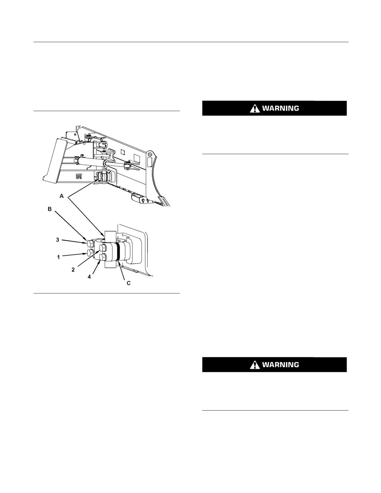
Note: The trunnion is a dry joint. Adding grease to
the trunnion simply attracts abrasive particles. The
Inspect/Replace
tightness of the joint should be monitored. Shims
should be removed when the joint becomes too
SMCS Code: 6801-040; 6801-510
loose. This may be indicated by excessive movement
in the blade.
Personal injury or death can result from bucket
falling.
Block the bucket before changing bucket cutting
edges.
1. Lower the lift arms fully. Tilt back the bucket so
that the bucket cutting edge is accessible.
2. Place blocks under the raised edge of the bucket.
3. Remove the bolts. Remove the cutting edge and
the end bits.
4. Clean the contact surfaces.
5. Use the opposite side of the cutting edge, if this
side is not worn.
6. Install a new cutting edge, if both edges are worn.
7. Install the bolts.
8. Remove the blocks that are under the bucket.
g01173519
9. After a few hours of operation, check the bolts for
Illustration 119
proper torque.
(A) Trunnion Joint
(B) Bolts
(C) Shims
i01764331
• Remove the four retaining bolts (B) and the cap.
Bucket Tips - Inspect/Replace
• Remove the necessary shims.
SMCS Code: 6805-040; 6805-510
• Replace the cap and bolts.
• The tightening sequence is shown in illustration
Personal injury or death can result from bucket
119.
falling.
• Torque the bolts to 530 ± 70 N·m (391 ± 52 lb ft).
Block the bucket before changing bucket cutting
edges.
Note: Some noise is typical and the noise does not
indicate a problem.
1. Lower the lift arms fully. Tilt back the bucket so
that the bucket tips are accessible.
2. Place blocks under the raised edge of the bucket.
3. Remove the mounting bolts. Remove the bucket
tips.
SEBU8407-06
137
Maintenance Section
Cab Air Filter - Clean/Replace
4. Clean the mounting surface.
3. Install the element. Replace the cover and tighten
the thumb screw.
5. Replace the bucket tips.
Recirculation Filter
6. Install the bolts.
7. Remove the blocks that are under the bucket.
8. After a few hours of operation, check the bolts for
proper torque.
i02417532
Cab Air Filter - Clean/Replace
(If Equipped)
SMCS Code: 7342-070; 7342-510
Fresh Air Filter
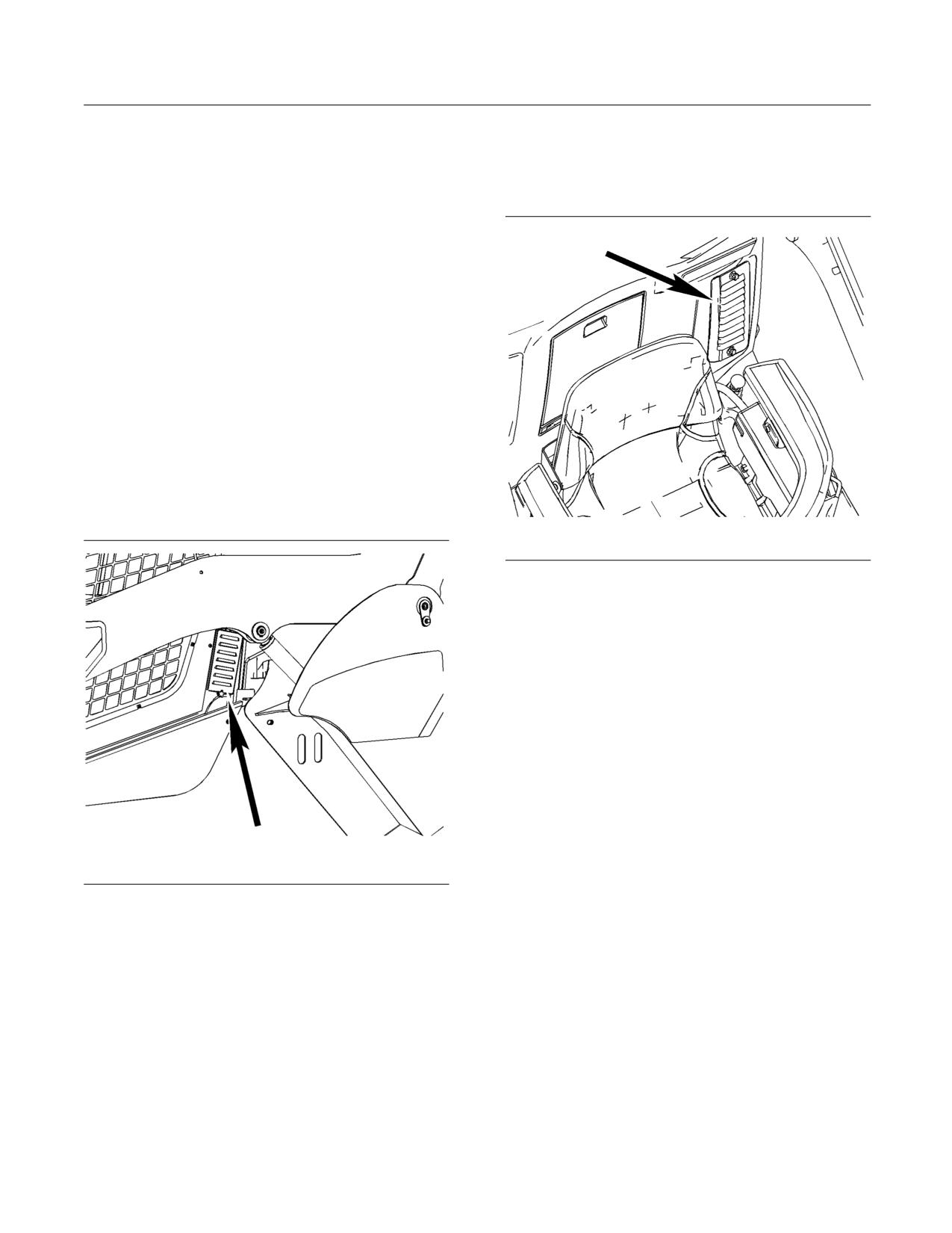
Note: The cover for the cab air filter is located on the
left hand side of the machine behind the cab.
g01209486
Illustration 121
1. Turn the thumb screws until the thumb screws are
free from the duct. Remove the cover.
2. Remove the air filter element from the duct and
clean the filter element with low pressure air
(maximum 207 kPa (30 psi)). Direct the air flow
up the pleats and down the pleats from the side
of the filter opposite of the air flow. Replace
the element if the element is damaged or if the
element seal is damaged. Replace the element if
the air conditioner performance is low.
Note: Do not use water for cleaning the filter.
3. Install the element. Replace the cover and tighten
the thumb screws.
g01287414
Illustration 120
i02616708
1. Turn the thumb screw until the thumb screw is free
Cab Interior - Clean
from the duct. Lift up on the cover and remove
the cover.
SMCS Code: 7301-070
2. Remove the air filter element from the duct and
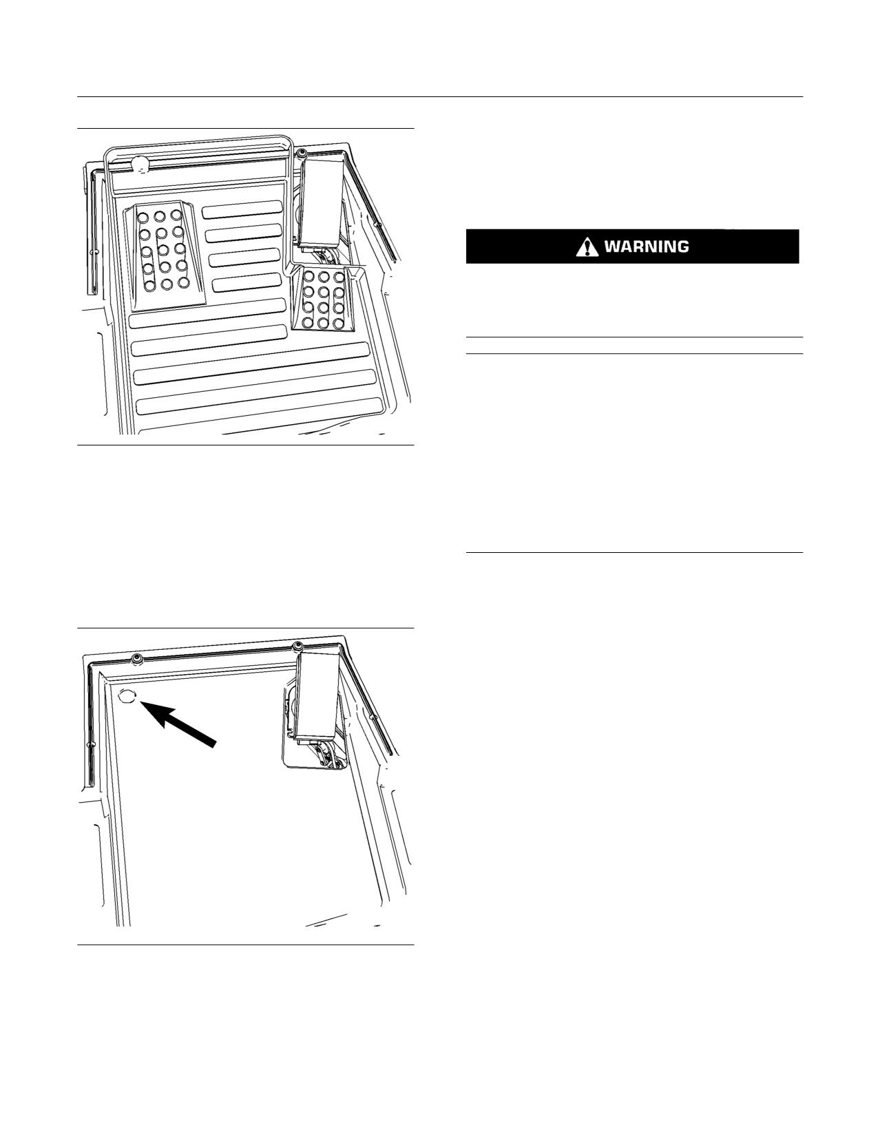
The floor mat is removable. The floor mat has sides
clean the filter element with low pressure air
in order to help retain the material.
(maximum 207 kPa (30 psi)). Direct the air flow
up the pleats and down the pleats from the side
of the filter opposite of the air flow. Replace
the element if the element is damaged or if the
element seal is damaged. Replace the element if
the air conditioner performance is low.
Note: Do not use water for cleaning the filter.
138
SEBU8407-06
Maintenance Section
Cooling System Coolant (ELC) - Change
i02807909
Cooling System Coolant (ELC)
- Change
SMCS Code: 1395-044-NL
Pressurized system: Hot coolant can cause seri-
ous burn. To open cap, stop engine, wait until ra-
diator is cool. Then loosen cap slowly to relieve
the pressure.
NOTICE
Mixing ELC with other products will reduce the effec-
tiveness of the coolant.
This could result in damage to cooling system compo-
nents.
g01312450
Illustration 122
Floor mat in the cab
If Caterpillar products are not available and com-
mercial products must be used, make sure they
The floor mat does not protect the foot pedal and
have passed the Caterpillar EC-1 specification for
the pedal linkage. Debris may accumulate around
pre-mixed or concentrate coolants and Caterpillar
the foot pedal. The foot pedal must be kept clear of
Extender.
excessive dirt and debris in order to ensure proper
activation of the pedal. Debris must be cleaned from
Note: The machine was shipped from the factory with
the area around the pedal. This can be done after
Extended Life Coolant (ELC) in the cooling system.
you remove the floor mat.
For information about the addition of Extender to your
cooling system, see the Operation and Maintenance
Manual, “Cooling System Coolant (ELC) Extender -
Add” or consult your Caterpillar dealer.
Drain the coolant whenever the coolant is dirty or
whenever the coolant is foaming.
The radiator cap is located under the radiator guard
on the top of the engine compartment.
Allow the machine to cool before you change the
coolant.
1. Open the engine access door. Refer to Operation
and Maintenance Manual, “Access Doors and
Covers”.
2. Raise the radiator guard. Refer to Operation and
Maintenance Manual, “Radiator Tilting”.
g01312452
Illustration 123
Note: The radiator cap is located on the right side
The drain on the left side of the machine
of the radiator.
You can wash the floor of the cab with water. There is
a drain in the front, left corner of the floor of the cab.
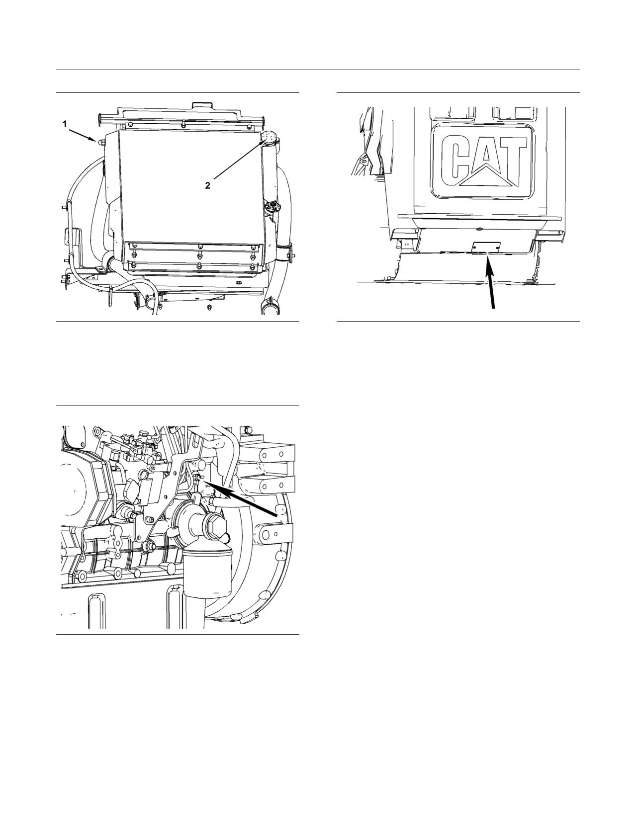
SEBU8407-06
139
Maintenance Section
Cooling System Coolant (ELC) - Change
g01210063
g01264593
Illustration 124
Illustration 126
(1) Sight gauge
(2) Radiator cap
5. Remove the access panel under the rear of the
machine. Pull the drain hose through the access
3. Slowly loosen the radiator cap (2) in order to
hole.
relieve system pressure. Remove the radiator cap.
6. Open the drain and allow the coolant to drain into
a suitable container.
7. Close the drain.
8. Push the hose back into the engine compartment.
Replace the access panel.
9. Replace the thermostat. See Operation and
Maintenance Manual, “Cooling System Water
Temperature Regulator - Replace” for the process
for replacing the thermostat.
10. Add the coolant solution directly to the radiator.
Do not use the coolant overflow reservoir as
a filler for the coolant. Refer to Operation and
Maintenance Manual, “Capacities - (Refill)”. Refer
to Special Publication, SEBU6250, “Caterpillar
Machine Fluids Recommendations”.
Note: Premix the coolant solution before filling
g01279512
the cooling system. The coolant solution should
Illustration 125
contain 50 percent coolant and 50 percent
Coolant drain
distilled water.
4. Locate the drain hose for the coolant system. The
Note: Add the coolant solution at a maximum rate
drain hose is attached to the drain valve that is
of five liters per minute. This will reduce the chance
shown in illustration 125.
of trapping air inside the engine block. A large amount
of trapped air can cause localized heating to occur
upon start-up. Localized heating may result in engine
damage, which may lead to failure of the engine.
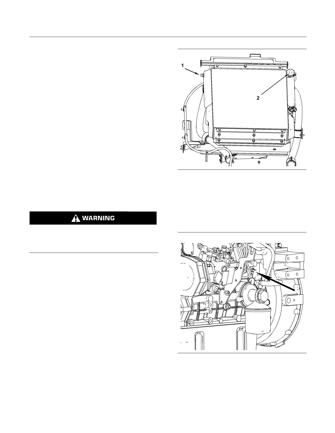
140
SEBU8407-06
Maintenance Section
Cooling System Coolant Extender (ELC) - Add
11. Start the engine. Run the engine without the
radiator cap until the thermostat opens and the
coolant level stabilizes. If necessary, add coolant.
Note: The sight gauge for the coolant level is located
on the left side of the radiator.
12. Check the coolant level in the sight gauge on the
radiator. Maintain the coolant level to the top of
the sight gauge with the radiator in the LOWERED
position.
13. Stop the engine. Inspect the radiator cap and the
gasket. Replace the cap if the cap or the gasket is
damaged. Install the radiator cap.
14. Pull the radiator guard downward.
15. Close the engine access door.
i02417747
g01210063
Illustration 127
Cooling System Coolant
(1) Sight gauge
(2) Radiator cap
Extender (ELC) - Add
Note: The radiator cap is located on the right side
SMCS Code: 1352-544-NL
of the radiator.
3. Slowly loosen the radiator cap in order to relieve
system pressure. Remove the radiator cap.
Pressurized system: Hot coolant can cause seri-
ous burn. To open cap, stop engine, wait until ra-
diator is cool. Then loosen cap slowly to relieve
the pressure.
When a Caterpillar Extended Life Coolant is used,
an extender must be added to the cooling system
periodically.
1. Open the engine access door. Refer to Operation
and Maintenance Manual, “Access Doors and
Covers”.
2. Tilt the radiator guard upward. Refer to Operation
and Maintenance Manual, “Radiator Tilting”.
g01279512
Illustration 128
Coolant drain
4. If necessary, drain enough coolant from the
radiator in order to allow the addition of the coolant
additive.
5. Add 0.17 L (0.18 qt) of cooling system additive.
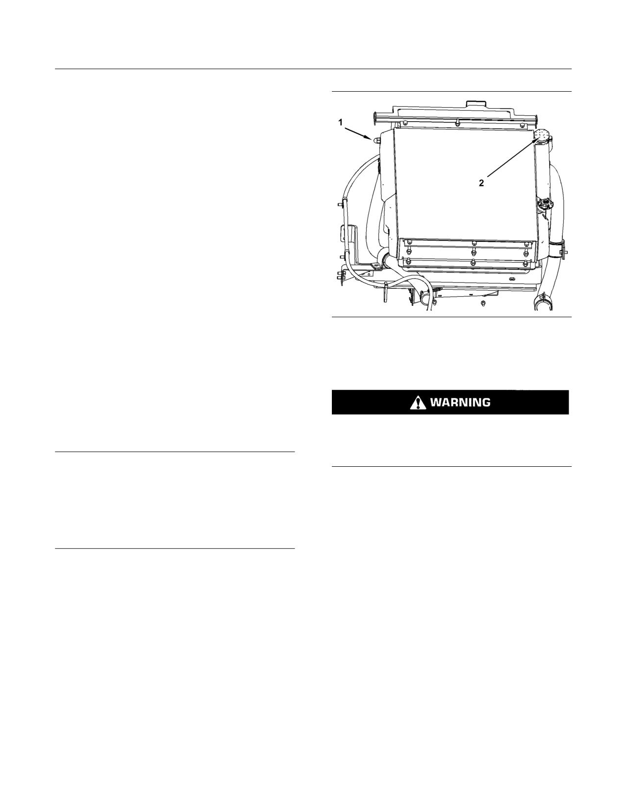
SEBU8407-06
141
Maintenance Section
Cooling System Coolant Sample (Level 1) - Obtain
6. Inspect the radiator cap and the gasket. If the cap
or the gasket is damaged, replace the cap. Install
the radiator cap.
Note: The sight gauge for the coolant is located on
the left side of the radiator on machines that are
equipped with the 3044 engine.
7. Check the coolant level in the sight gauge on the
radiator. Maintain the coolant level to the top of
the sight gauge with the radiator in the LOWERED
position.
8. Add the extender directly to the radiator. Do not
use the coolant overflow reservoir as a filler for
the extender.
9. Tilt the radiator guard downward.
10. Close the engine access door.
For additional information on the addition of extender,
g01210063
Illustration 129
see Special Publication, SEBU6250, “Caterpillar
Machine Fluids Recommendations”.
Refer to the Operation and Maintenance Manual,
“Access Doors and Covers” for the location of the
service points.
i02664591
Cooling System Coolant
Sample (Level 1) - Obtain
Pressurized system: Hot coolant can cause seri-
SMCS Code: 1350-008; 1395-008; 7542
ous burn. To open cap, stop engine, wait until ra-
diator is cool. Then loosen cap slowly to relieve
the pressure.
NOTICE
Always use a designated pump for oil sampling, and
use a separate designated pump for coolant sampling.
Obtain the sample of the coolant from the radiator.
Using the same pump for both types of samples may
When the system is cool, slowly remove the radiator
contaminate the samples that are being drawn. This
cap (2).
contaminate may cause a false analysis and an incor-
rect interpretation that could lead to concerns by both
Note: Do not take the sample from the Coolant
dealers and customers.
Overflow Reservoir.
Obtain the sample of the coolant as close as possible
Note: Level 1 results may indicate a need for
to the recommended sampling interval. In order
Level 2 Analysis.
to receive the full effect of S·O·S analysis, you
must establish a consistent trend of data. In order
to establish a pertinent history of data, perform
consistent samplings that are evenly spaced.
Supplies for collecting samples can be obtained from
your Caterpillar dealer.
Use the following guidelines for proper sampling of
the coolant:
• Keep the unused sampling bottles stored in plastic
bags.
• Keep the lids on empty sampling bottles until you
are ready to collect the sample.
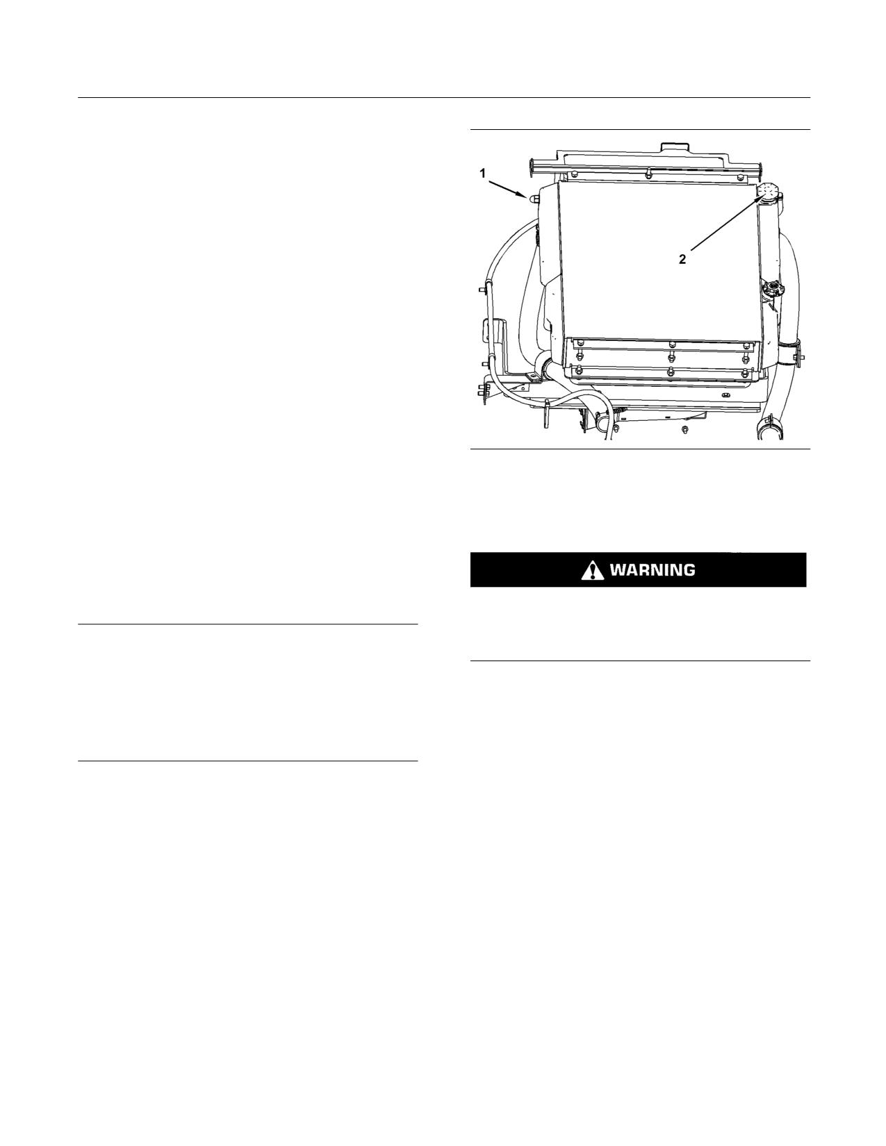
142
SEBU8407-06
Maintenance Section
Cooling System Coolant Sample (Level 2) - Obtain
• Complete the information on the label for the
sampling bottle before you begin to take the
samples.
• Use a designated pump to collect the sample in
order to avoid contamination.
• Obtain coolant samples directly from the coolant
tank. You should not obtain the samples from any
other location.
• Place the sample in the mailing tube immediately
after obtaining the sample in order to avoid
contamination.
• Never collect samples from the drain for a system.
Submit the sample for Level 1 analysis.
For additional information about coolant analysis, see
Special Publication, SEBU6250, “Caterpillar Machine
Fluids Recommendations” or consult your Caterpillar
g01210063
Illustration 130
dealer.
Refer to the Operation and Maintenance Manual,
“Access Doors and Covers” for the location of the
i02664598
service points.
Cooling System Coolant
Sample (Level 2) - Obtain
SMCS Code: 1350-008; 1395-008; 7542
Pressurized system: Hot coolant can cause seri-
ous burn. To open cap, stop engine, wait until ra-
diator is cool. Then loosen cap slowly to relieve
NOTICE
the pressure.
Always use a designated pump for oil sampling, and
use a separate designated pump for coolant sampling.
Using the same pump for both types of samples may
Obtain the sample of the coolant from the radiator.
contaminate the samples that are being drawn. This
When the system is cool, slowly remove the radiator
contaminate may cause a false analysis and an incor-
cap (2).
rect interpretation that could lead to concerns by both
dealers and customers.
Note: Do not take the sample from the Coolant
Overflow Reservoir.
Obtain the sample of the coolant as close as possible
to the recommended sampling interval. Supplies
for collecting samples can be obtained from your
Caterpillar dealer.
Refer to Operation and Maintenance Manual,
“Cooling System Coolant Sample (Level 1) - Obtain”
for the guidelines for proper sampling of the coolant.
Submit the sample for Level 2 analysis.
For additional information about coolant analysis, see
Special Publication, SEBU6250, “Caterpillar Machine
Fluids Recommendations” or consult your Caterpillar
dealer.
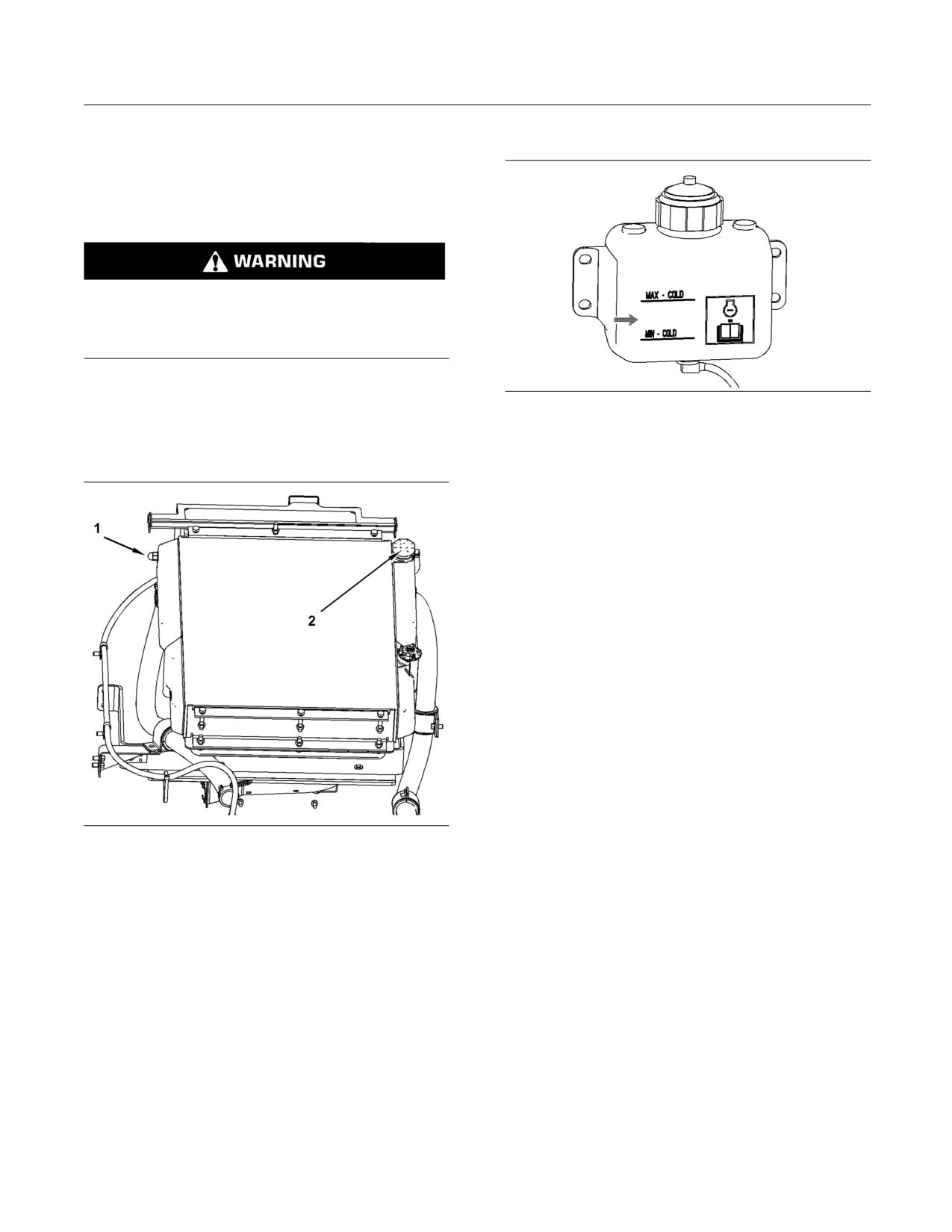
SEBU8407-06
143
Maintenance Section
Cooling System Level - Check
i02417701
5. Tilt the radiator guard downward.
Cooling System Level - Check
SMCS Code: 1350-040-HX; 1350-535-FLV;
1382-070; 1382-510
Pressurized system: Hot coolant can cause seri-
ous burn. To open cap, stop engine, wait until ra-
diator is cool. Then loosen cap slowly to relieve
the pressure.
1. Open the engine access door. Refer to Operation
g01018341
and Maintenance Manual, “Access Doors and
Illustration 132
Covers”.
6. The coolant overflow reservoir is located on the
2. Tilt the radiator guard upward.
rear door. Maintain the coolant level in the coolant
overflow reservoir between the “MIN” and “MAX”
lines.
7. Close the engine access door.
i03880044
Cooling System Water
Temperature Regulator -
Replace
SMCS Code: 1355-510; 1393-010
Replace the thermostat on a regular basis in order to
reduce the chance of unscheduled downtime and of
problems with the cooling system. Failure to replace
the engine's thermostat on a regularly scheduled
basis could cause severe engine damage.
The thermostat should be replaced after the cooling
g01210063
Illustration 131
system has been cleaned. Replace the thermostat
(1) Sight gauge
while the cooling system is completely drained or
(2) Radiator cap
while the cooling system coolant is drained to a level
that is below the thermostat housing.
3. Check the coolant level in the sight gauge (1)
on the radiator. Maintain the coolant level to the
Caterpillar engines incorporate a shunt design
top of the sight gauge with the radiator in the
cooling system. It is mandatory to always operate the
LOWERED position. If you need to add coolant,
engine with a thermostat.
add the coolant directly to the radiator. Remove
the radiator cap (2) slowly in order to relieve
1. Open the engine access door. Refer to Operation
system pressure.
and Maintenance Manual, “Access Doors and
Covers”.
Note: The radiator cap is located on the right side
of the radiator. Inspect the cooling system hoses for
2. Drain the coolant from the machine. See Operation
any leaks, cracks, or signs of deterioration. Replace
and Maintenance Manual, “Cooling System
any damaged hoses.
Coolant (ELC) - Change” for the procedure to
drain the cooling system.
4. Inspect the radiator cap and the gasket. Replace
the cap if the cap or the gasket is damaged. Install
the radiator cap.
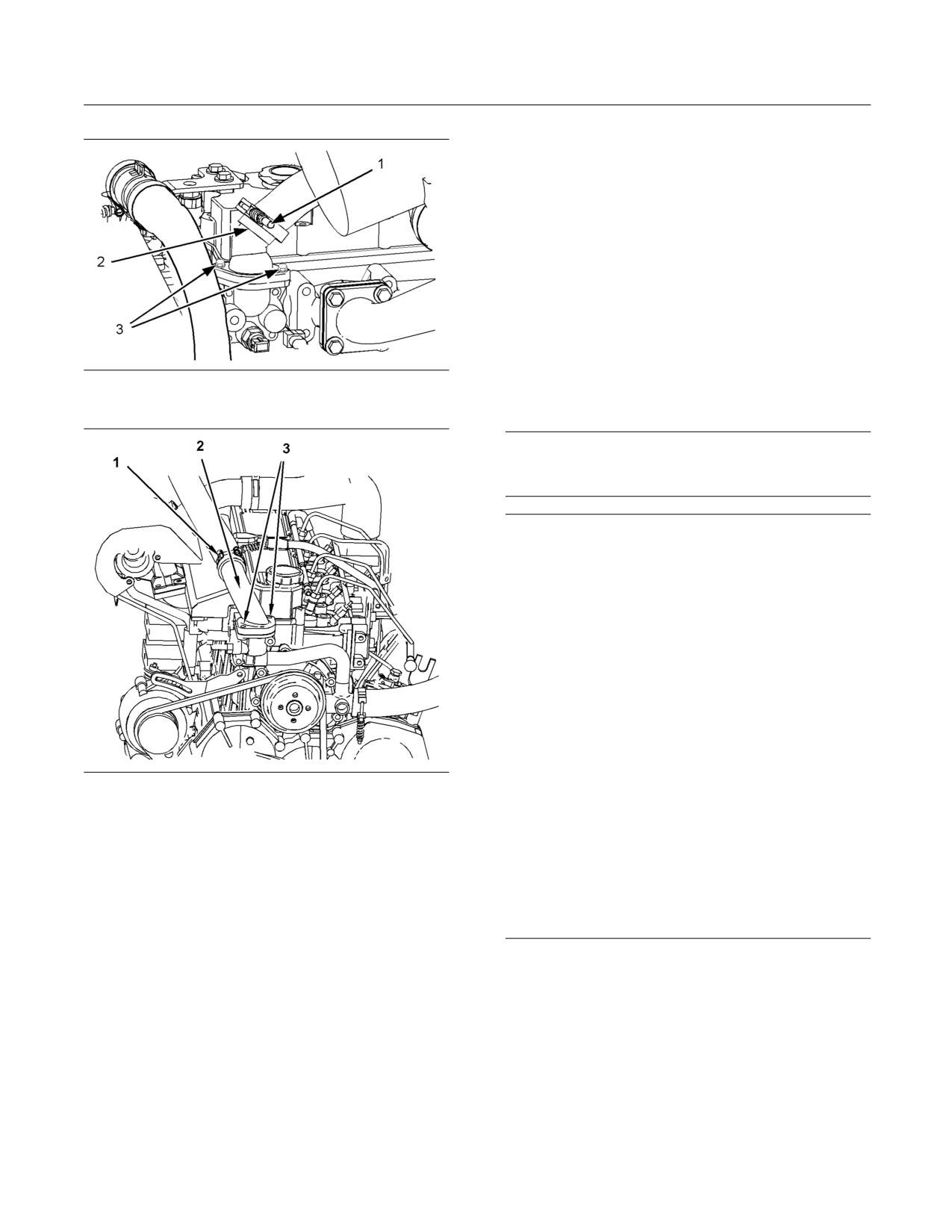
144
SEBU8407-06
Maintenance Section
Engine Air Filter Primary Element - Clean/Replace
8. Refill the cooling system. Refer to Operation and
Maintenance Manual, “Capacities - (Refill)”. Refer
to Operation and Maintenance Manual, “Cooling
System Coolant (ELC) - Change” for information
about refilling the cooling system. Refer to Special
Publication, SEBU6250, “Caterpillar Machine
Fluid Recommendations” for coolant information.
9. Close the engine access door.
i02417909
Engine Air Filter Primary
Element - Clean/Replace
g01018412
Illustration 133
C2.2
SMCS Code: 1054-070-PY; 1054-510-PY
NOTICE
Never service the air cleaner when the engine is run-
ning, to avoid engine damage.
NOTICE
Caterpillar recommends certified air filter cleaning ser-
vices that are available at Caterpillar dealers. The
Caterpillar cleaning process uses proven procedures
to assure consistent quality and sufficient filter life.
Observe the following guidelines if you attempt to
clean the filter element:
Do not tap or strike the filter element in order to re-
move dust.
Do not wash the filter element.
Use low pressure compressed air in order to remove
g01210045
Illustration 134
the dust from the filter element. Air pressure must not
exceed 207 kPa (30 psi). Direct the air flow up the
C3.4
pleats and down the pleats from the inside of the filter
element. Take extreme care in order to avoid damage
3. Loosen the hose clamp (1) and remove the hose
to the pleats.
from the thermostat housing assembly (2).
Do not use air filters with damaged pleats, gaskets, or
4. Remove the two bolts (3) from the thermostat
seals. Dirt entering the engine will cause damage to
housing assembly. Remove the thermostat
engine components.
housing assembly.
5. Remove the seal and the thermostat from the
Service the air filter elements when the alert indicator
thermostat housing assembly.
for air filter restriction lights. Refer to Operation
and Maintenance Manual, “Alert Indicators” for
6. Install a new thermostat and a new seal. Install
information about the indicator.
the thermostat housing assembly on the engine
cylinder head.
7. Install the hose. Tighten the hose clamp.
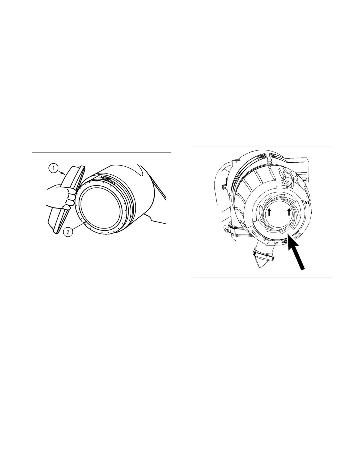
SEBU8407-06
145
Maintenance Section
Engine Air Filter Primary Element - Clean/Replace
Clean
Note: Do not use a primary air filter element that has
any tears and/or holes in the filter material. Do not
The primary filter element can be used up to
use a primary air filter element with damaged pleats,
three times if the element is properly cleaned and
gaskets or seals. Discard damaged primary air filter
if the element is properly inspected. When the
elements.
primary filter element is cleaned, check for rips or
tears in the filter material. The primary filter element
7. Clean the inside of the air cleaner housing with a
should be replaced at least one time per year. This
damp cloth. Do not use compressed air to clean
replacement should be performed regardless of the
the housing.
number of cleanings.
8. Install the primary filter element into the filter
1. Open the engine access door.
housing.
2. The air filter housing is located on the right side of
9. Install the cover for the filter housing.
the engine compartment.
g00101864
Illustration 135
3. Unlatch the air cleaner housing cover (1). Rotate
the cover counterclockwise and remove the cover.
4. Remove the primary filter element (2).
g01276795
Illustration 136
5. If it is appropriate, clean the primary filter element.
10. Rotate the cover clockwise and latch the cover.
Use air pressure to clean the primary filter
elements. Pressurized air will not remove deposits
Note: Make sure that the cover is properly positioned.
of carbon and oil. Use filtered, dry air with a
The arrows on the air filter cover should point upward
maximum pressure of 207 kPa (30 psi).
when the cover is in the locked position.
Note: When the primary filter elements are cleaned,
11. Close the engine access door.
always begin with the inside in order to force dirt
particles toward the outside. Aim the hose so that the
12. Start the engine. The alert indicator for air filter
air flows inside the element along the length of the
restriction should turn off. If the alert indicator
filter in order to help prevent damage to the paper
continues to light, replace the secondary air filter.
pleats. Do not aim the stream of air directly at the
Refer to Operation and Maintenance Manual,
primary filter element.
“Engine Air Filter Secondary Element - Replace”.
6. Inspect the cleaned, dry primary air filter element.
Use a 60 watt blue light in a dark room or in a
Replace
similar facility. Place the blue light in the primary
air filter element. Rotate the primary air filter
The primary filter element should be replaced at least
element. Inspect the primary air filter element for
one time per year. You can clean the primary filter
tears and/or holes. Inspect the primary air filter
up to three times.
element for light that may show through the filter
material. If it is necessary in order to confirm the
1. Open the engine access door.
result, compare the primary air filter element to a
new primary air filter element that has the same
2. The air filter housing is located on the right side of
part number.
the engine compartment.
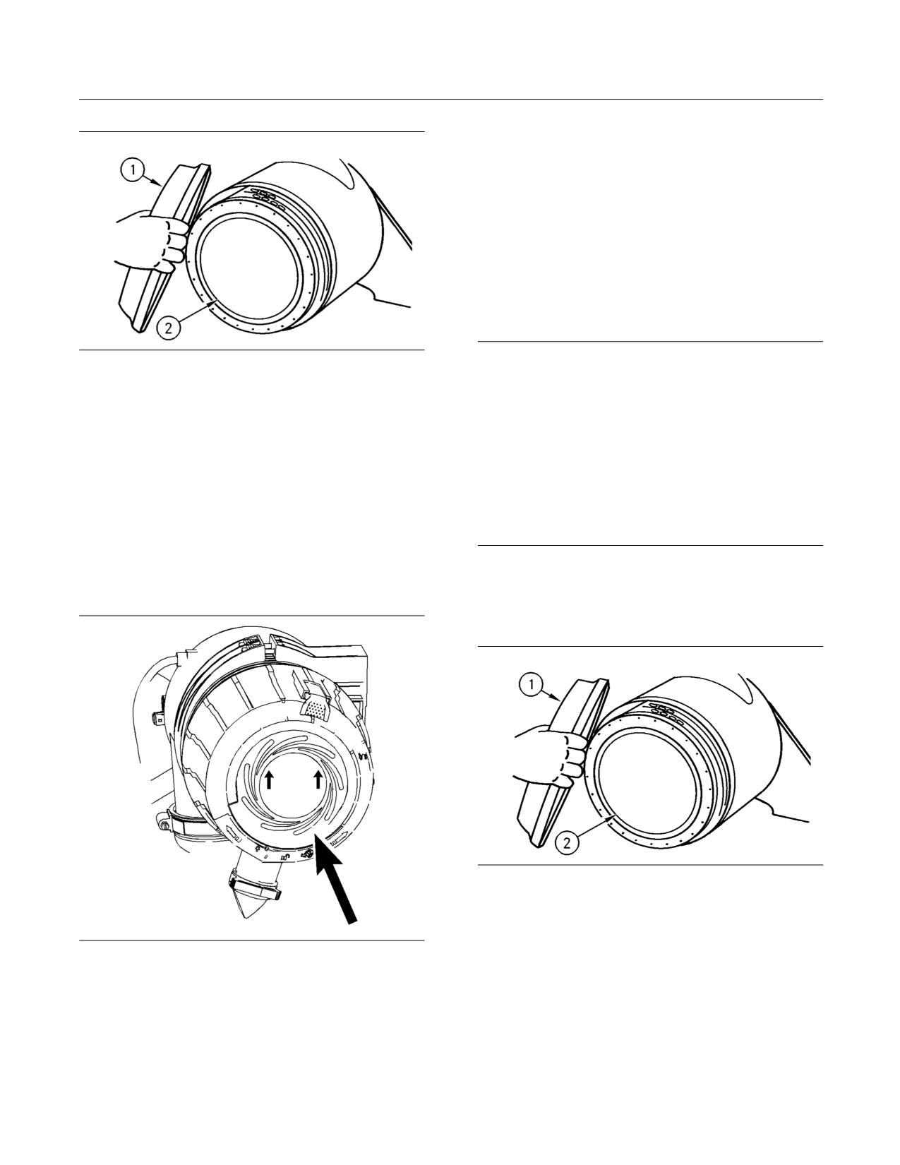
146
SEBU8407-06
Maintenance Section
Engine Air Filter Secondary Element - Replace
10. Start the engine. The alert indicator for air filter
restriction should turn off. If the alert indicator
continues to light, replace the secondary air filter.
Refer to Operation and Maintenance Manual,
“Engine Air Filter Secondary Element - Replace”.
i02417939
Engine Air Filter Secondary
Element - Replace
SMCS Code: 1054-510-SE
g00101864
NOTICE
Illustration 137
Always replace the secondary filter element. Nev-
er attempt to reuse the secondary filter element by
3. Unlatch the air cleaner housing cover (1). Rotate
cleaning the element.
the cover counterclockwise and remove the cover.
When the primary filter element is cleaned for the third
4. Remove the primary filter element (2).
time, the secondary filter element should be replaced.
5. Clean the inside of the air cleaner housing with a
The secondary filter element should also be replaced
damp cloth. Do not use compressed air to clean
if the restricted Air Filter indicator comes on after the
the housing.
installation of a clean primary filter element or if the
exhaust smoke is still black.
6. Install a new primary filter element into the filter
housing.
1. Open the engine access door.
7. Install the cover for the filter housing.
2. The air filter housing is located on the right side of
the engine compartment.
g00101864
Illustration 139
3. Unlatch the air cleaner housing cover (1). Rotate
the cover counterclockwise and remove the cover.
g01276795
Illustration 138
4. Remove the primary filter element (2).
8. Rotate the cover clockwise and latch the cover.
Note: Make sure that the cover is properly positioned.
The arrows on the air filter cover should point upward
when the cover is in the locked position.
9. Close the engine access door.
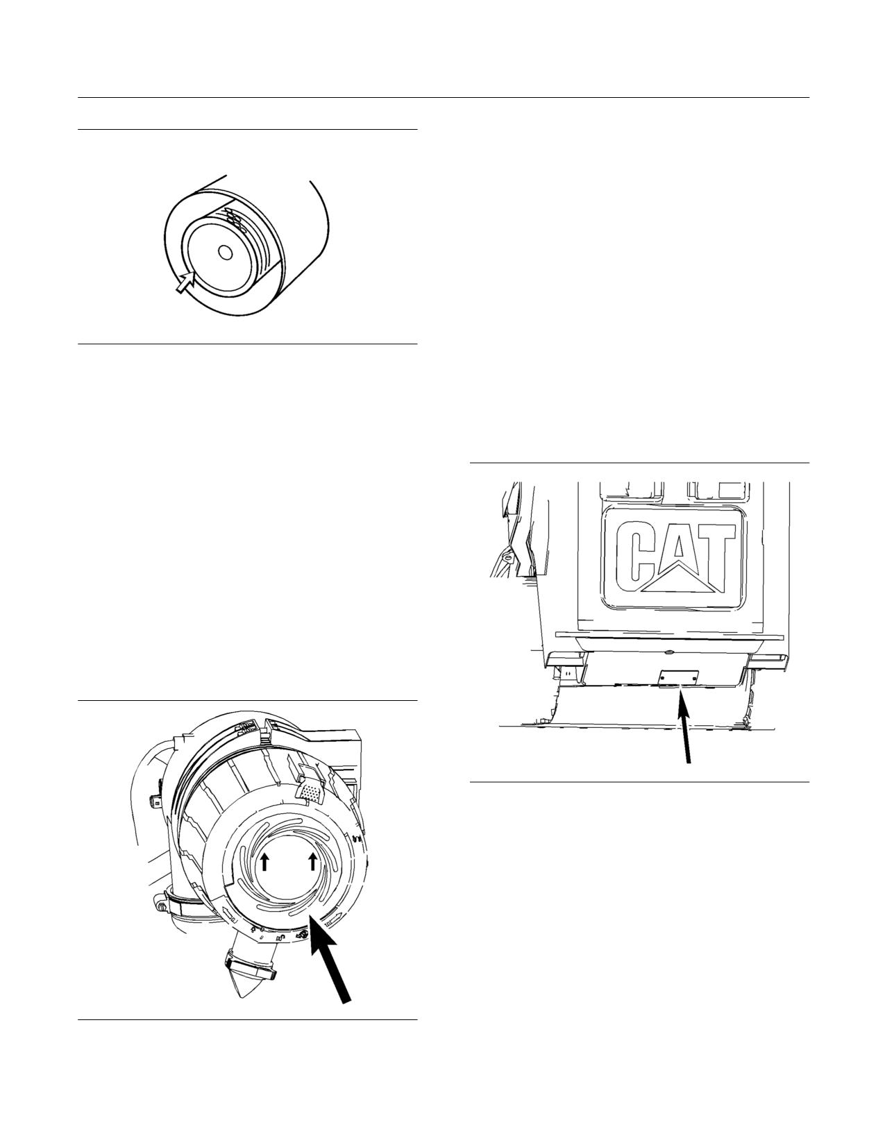
SEBU8407-06
147
Maintenance Section
Engine Compartment - Inspect/Clean
Note: Make sure that the cover is properly positioned.
The arrows on the air filter cover should point upward
when the cover is in the locked position.
14. Close the engine access door.
i02834984
Engine Compartment -
Inspect/Clean
SMCS Code: 1000-040-CPA; 1000-070-CPA
Inspect the engine compartment for dirt buildup or
g00038606
Illustration 140
debris. Remove any dirt or debris from the engine
compartment.
5. Clean the inside of the air cleaner housing with a
damp cloth. Do not use compressed air to clean
1. Open the engine access door. Refer to Operation
the housing.
and Maintenance Manual, “Access Doors and
Covers”.
6. Remove the secondary filter element.
7. Cover the air inlet opening.
8. Clean the inside of the air cleaner housing with a
damp cloth, if necessary. Do not use compressed
air to clean the housing.
9. Uncover the air inlet opening.
10. Install a new secondary element.
11. Install the primary element.
12. Install the cover for the filter housing.
g01264593
Illustration 142
2. Remove any debris or dirt from the engine
compartment. If necessary, remove the
access panel in order to clean out the engine
compartment.
Note: Use care when you clean the engine
compartment. Damage to the machine may occur.
3. Install the access panel. Close the engine access
door.
g01276795
Illustration 141
13. Rotate the cover clockwise and latch the cover.
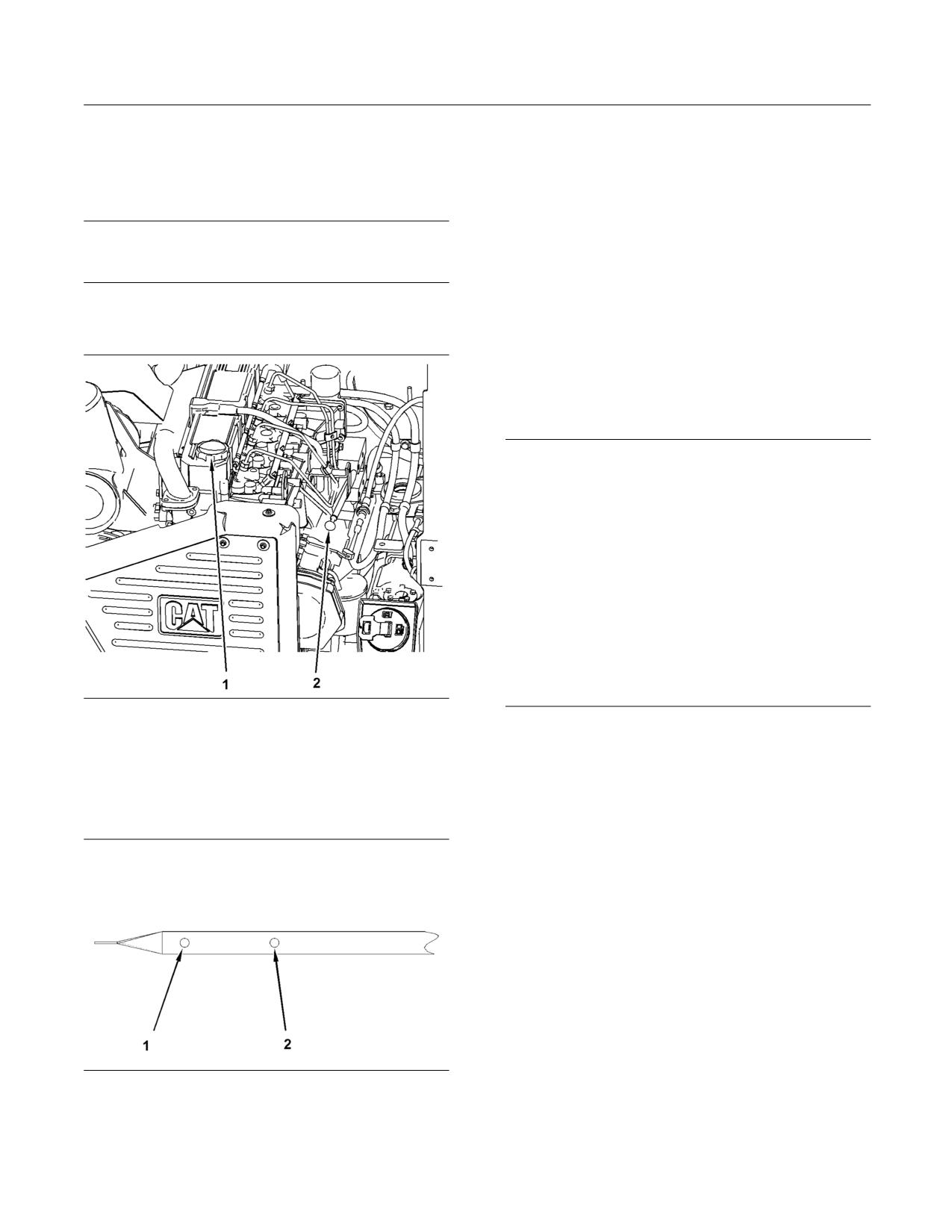
148
SEBU8407-06
Maintenance Section
Engine Oil Level - Check
i02417992
4. If oil is necessary, tilt the radiator upward. Refer
to Operation and Maintenance Manual, “Radiator
Engine Oil Level - Check
Tilting”.
SMCS Code: 1348-535-FLV
5. Remove the oil filler cap (1) and add oil.
NOTICE
6. Clean the oil filler cap and install the oil filler cap.
Do not overfill the crankcase. Engine damage can re-
sult.
7. Tilt the radiator downward.
8. Close the engine access door.
1. Stop the engine and allow the oil to drain back
into the oil pan.
i02743337
Engine Oil and Filter - Change
SMCS Code: 1308-510; 1348-044
NOTICE
Care must be taken to ensure that fluids are contained
during performance of inspection, maintenance, test-
ing, adjusting and repair of the product. Be prepared to
collect the fluid with suitable containers before open-
ing any compartment or disassembling any compo-
nent containing fluids.
Refer to Special Publication, NENG2500, “Caterpillar
Dealer Service Tool Catalog” for tools and supplies
suitable to collect and contain fluids on Caterpillar
products.
Dispose of all fluids according to local regulations and
mandates.
g01209758
Illustration 143
(1) Oil Filler Cap
The normal oil change interval for the machine is
(2) Dipstick
Every 500 Service Hours or every year when the
following conditions are met:
2. Open the engine access door. Refer to Operation
and Maintenance Manual, “Access Doors and
• Use an engine oil in the Operation and Maintenance
Covers”.
Manual, “Lubricant Viscosities”.
• Caterpillar filters are used.
• The altitude does not exceed 2300 m (7545 ft).
• Sulfur content in the fuel is between 0.05% and
0.50%.
An oil change interval of Every 250 Service Hours
or every six months is required when the following
conditions occur:
• Use an engine oil in the Operation and Maintenance
Manual, “Lubricant Viscosities”.
g01277108
Illustration 144
• The altitude exceeds 2300 m (7545 ft).
(1) Oil level add mark
(2) Full mark
• Sulfur content in the fuel is between 0.50% and
1.00%.
3. Maintain the oil level between the “ADD” (1) mark
and the “FULL” (2) mark on the dipstick.
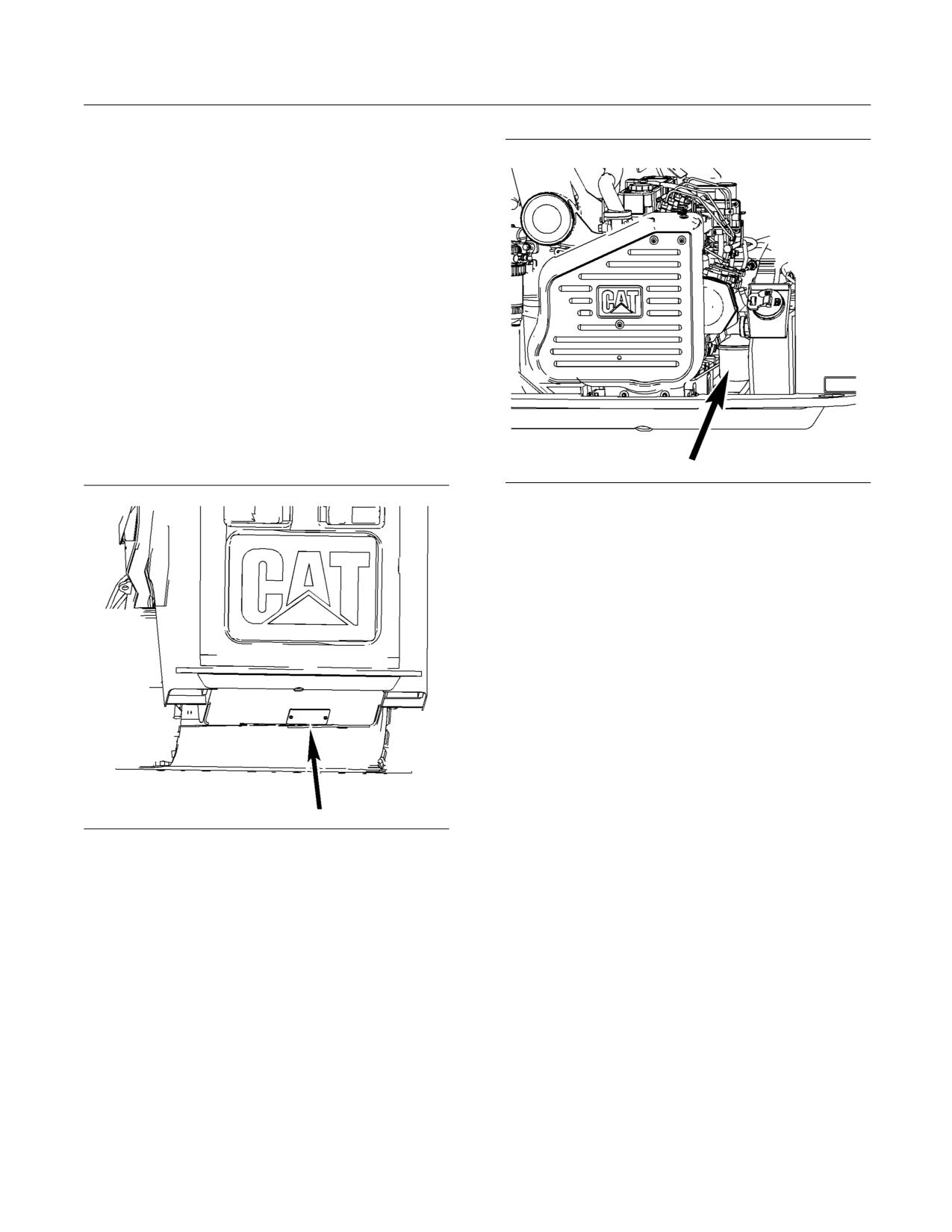
SEBU8407-06
149
Maintenance Section
Engine Oil and Filter - Change
An oil change interval of Every 125 Service Hours is
required when the following condition occurs:
• Sulfur content in the fuel is above 1.00%.
Refer to the results of the S·O·S oil analysis in
order to determine if the oil change interval should
be decreased. Consult your Caterpillar Dealer for
detailed information regarding the optimum oil
change interval.
1. Open the engine access door. Refer to Operation
and Maintenance Manual, “Access Doors and
Covers”.
2. Tilt the radiator upward. Refer to Operation and
Maintenance Manual, “Radiator Tilting”.
Note: The crankcase drain is located on the right
side of the oil pan.
g01209695
Illustration 146
4. Remove the filter element with a 187-2718 Filter
Wrench. Refer to Operation and Maintenance
Manual, “Oil Filter - Inspect” in order to inspect
the used filter for debris.
5. Apply a thin film of clean engine oil to the sealing
surface of the new filter element.
6. Install a new engine oil filter hand tight until the
seal of the engine oil filter contacts the base. Note
the position of the index marks on the filter in
relation to a fixed point on the filter base.
Note: There are rotation index marks on the engine
oil filter that are spaced 90 degrees or 1/4 of a turn
away from each other. When you tighten the engine
oil filter, use the rotation index marks as a guide.
g01264593
7. Tighten the filter according to the instructions
Illustration 145
that are printed on the filter. Use the index marks
3. Remove the access panel that is located below
as a guide. For non-Caterpillar filters, use the
the drain plug. Remove the drain plug and allow
instructions that are provided with the filter.
the oil to drain into a suitable container. Install the
drain plug and install the access panel.
Note: You may need to use a Caterpillar strap
wrench, or another suitable tool, in order to turn
the filter to the amount that is required for final
installation. Make sure that the installation tool does
not damage the filter.
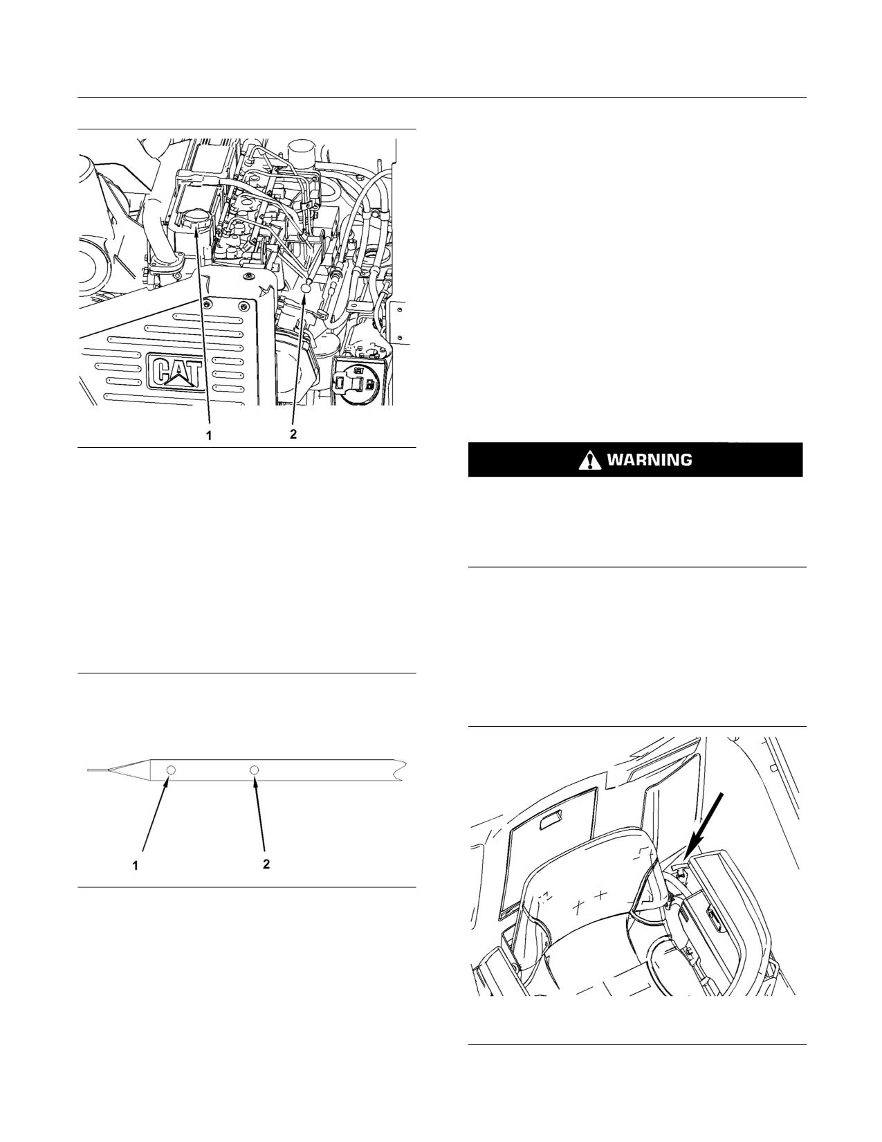
150
SEBU8407-06
Maintenance Section
Engine Valve Lash - Check
i01020861
Engine Valve Lash - Check
SMCS Code: 1105-025
Refer to the Service Manual for the complete
adjustment procedure for the engine valve lash.
A qualified mechanic should adjust the engine valve
lash and the fuel injector timing because special tools
and training are required.
i02808037
Equipment Lowering Control
Valve - Check
SMCS Code: 5147-MA
g01209758
Illustration 147
(1) Oil Filler Cap
(2) Dipstick
Personal injury or death can result from a work
tool falling.
8. Remove the oil filler cap (1). Fill the crankcase
with new oil. Refer to Operation and Maintenance
Keep personnel away from the front of the ma-
Manual, “Lubricant Viscosities” and Operation
chine when lowering the work tool.
and Maintenance Manual, “Refill Capacities” for
information about the oil. Clean the oil filler plug
Before lowering any equipment, clear the area
and install the oil filler plug.
around the equipment of all personnel.
9. Start the engine and allow the oil to warm. Check
1. Lower arms to the fully lowered position. Turn the
for leaks.
keyswitch to the OFF position.
2. Slide the seat forward. Slide the left hand armrest
forward.
g01277108
Illustration 148
(1) Oil level add mark
(2) Full mark
10. Stop the engine and allow the oil to drain back
into the oil pan. Fill the crankcase to the “FULL”
mark (2) on the dipstick. Do not exceed the
“FULL” mark on the dipstick. Add oil or drain
oil if it is necessary.
g01400888
11. Tilt the radiator downward.
Illustration 149
12. Close the engine access door.
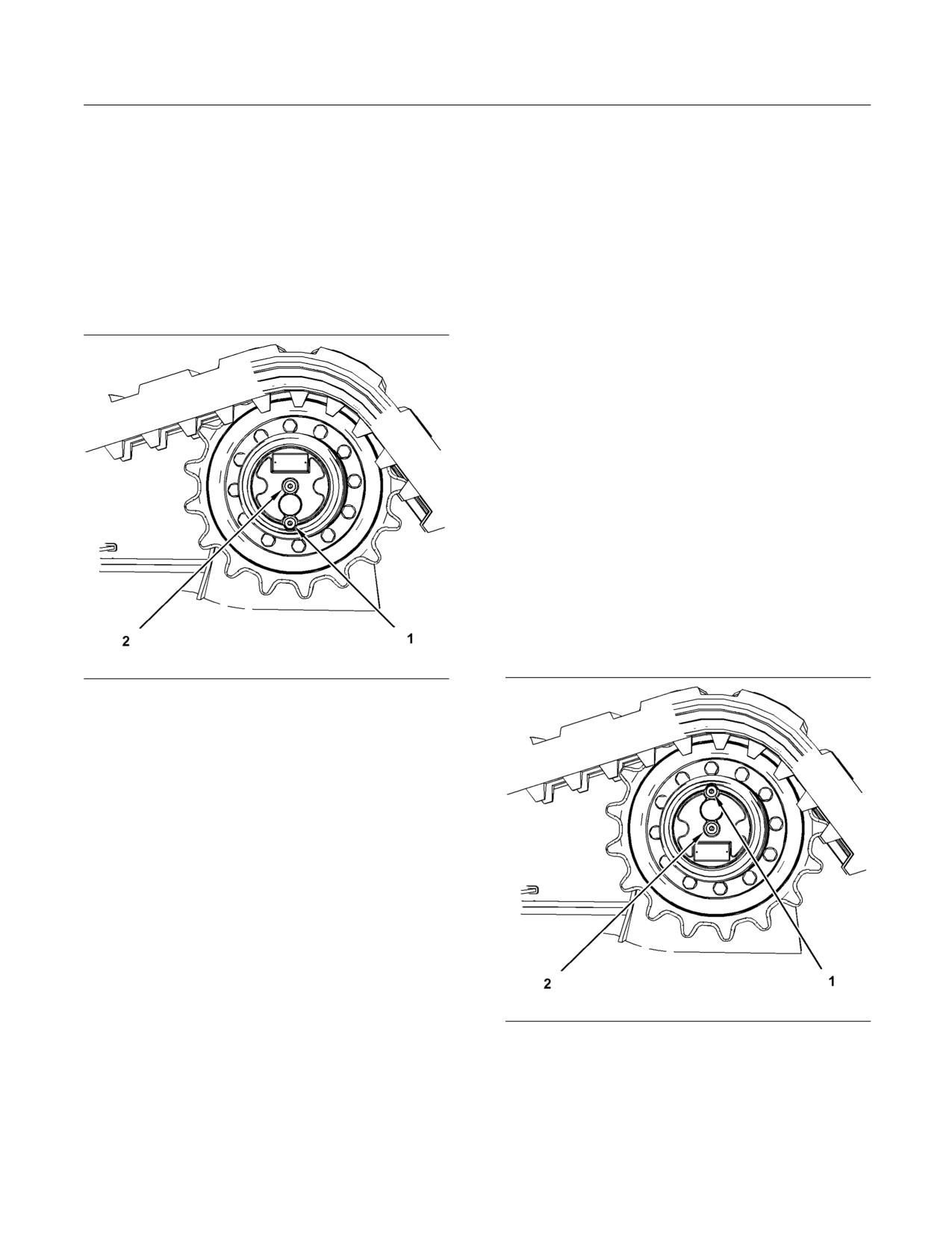
SEBU8407-06
151
Maintenance Section
Final Drive Oil - Change
3. Pull up on the red handle in order to fully actuate
6. Add oil through the opening of the oil fill/drain plug
the valve.
(1) that is now at the top.
4. Push the red handle to the original position.
7. Fill the final drive to the bottom of the opening
Ensure that the handle is fully seated.
for the oil check plug (2). Refer to Operation and
Maintenance Manual, “Lubricant Viscosities” and
Operation and Maintenance Manual, “Capacities
i02919737
(Refill)”.
Final Drive Oil - Change
8. Install the two oil plugs. Tighten the oil plugs to a
torque of 27 ± 1 N·m (20 ± 0.7 lb ft).
SMCS Code: 4050-044-OC
9. Perform Step 1 to Step 8 on the other final drive.
10. Completely remove any oil that has spilled.
11. Start the engine and allow the final drives to
operate through several cycles.
12. Stop the engine.
13. Check the oil level.
14. Maintain the oil level to the bottom of the opening
for the fill/drain plug (2).
i02919749
Final Drive Oil Level - Check
SMCS Code: 4050-535-FLV
g01451295
Illustration 150
(1) Oil fill/drain plug
(2) Oil check plug
1. Position one final drive so that the oil fill/drain plug
(1) is at the bottom.
Note: Refer to Operation and Maintenance Manual,
“General Hazard Information” for information on
containing fluid spillage.
2. Use an 8 mm (5/16 inch) allen wrench. Remove
the oil plugs (1) and (2). Allow the oil to drain into
a suitable container.
3. Check the drained oil for metal chips or for
particles. If there are any chips or particles, consult
your Caterpillar dealer.
Note: Dispose of drained fluids according to local
g01457009
regulations.
Illustration 151
(1) Oil fill/drain plug
4. Clean the plugs and inspect the plugs. Replace a
(2) Oil check plug
worn plug or a damaged plug.
1. Position one final drive so that the oil fill/drain plug
5. Position the final drive so that the oil fill/drain plug
(1) is at the top.
(1) is at the top.
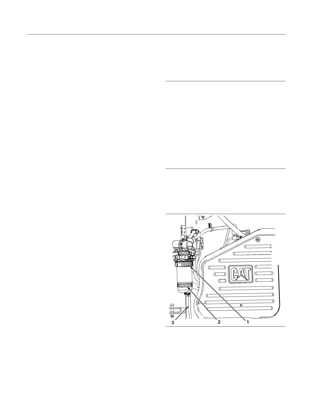
152
SEBU8407-06
Maintenance Section
Fuel Injection Timing - Check
Note: Refer to Operation and Maintenance Manual,
i02520136
“General Hazard Information” for information on
Fuel System Primary Filter
Containing Fluid Spillage.
(Water Separator) - Drain
2. Use an 8 mm (5/16 inch) allen wrench. Remove
the oil check plug (2).
SMCS Code: 1263-543
3. Check the oil level. The oil should be near the
NOTICE
bottom of the opening for the oil check plug (2).
Care must be taken to ensure that fluids are contained
during performance of inspection, maintenance, test-
4. Add oil through the opening for the oil fill/drain
ing, adjusting and repair of the product. Be prepared to
plug (1), if necessary.
collect the fluid with suitable containers before open-
ing any compartment or disassembling any compo-
Note: Overfilling the final drive will cause the seals on
nent containing fluids.
the travel motor to allow hydraulic oil or water to enter
the final drive. This may contaminate the final drive.
Refer to Special Publication, NENG2500, “Caterpillar
Dealer Service Tool Catalog” for tools and supplies
5. Clean the oil plugs.
suitable to collect and contain fluids on Caterpillar
products.
6. Install the oil plugs. Tighten the oil plugs to a
torque of 27 ± 1 N·m (20 ± 0.7 lb ft).
Dispose of all fluids according to local regulations and
mandates.
7. Repeat the procedure for the other final drive.
The fuel system water separator is located in the left
i00916186
side of the engine compartment.
Fuel Injection Timing - Check
1. Open the engine access door. Refer to Operation
and Maintenance Manual, “Access Doors and
SMCS Code: 1251-531
Covers”.
Note: The correct fuel timing specification is
found on the Engine Information Plate. Fuel
timing specifications may vary for different engine
applications and/or for different power ratings.
A qualified mechanic should adjust the fuel injection
timing because special tools and training are
required.
Refer to the Service Manual for the complete
adjustment procedure for the fuel injection timing.
Refer to your Caterpillar dealer for the complete
adjustment procedure for the fuel injection timing.
g01264527
Illustration 152
The Fuel Filter/Water Separator is located on the left side of the
engine compartment.
2. Insert the drain hose (3) into a suitable container.
Loosen the drain valve on the bottom of the water
separator.
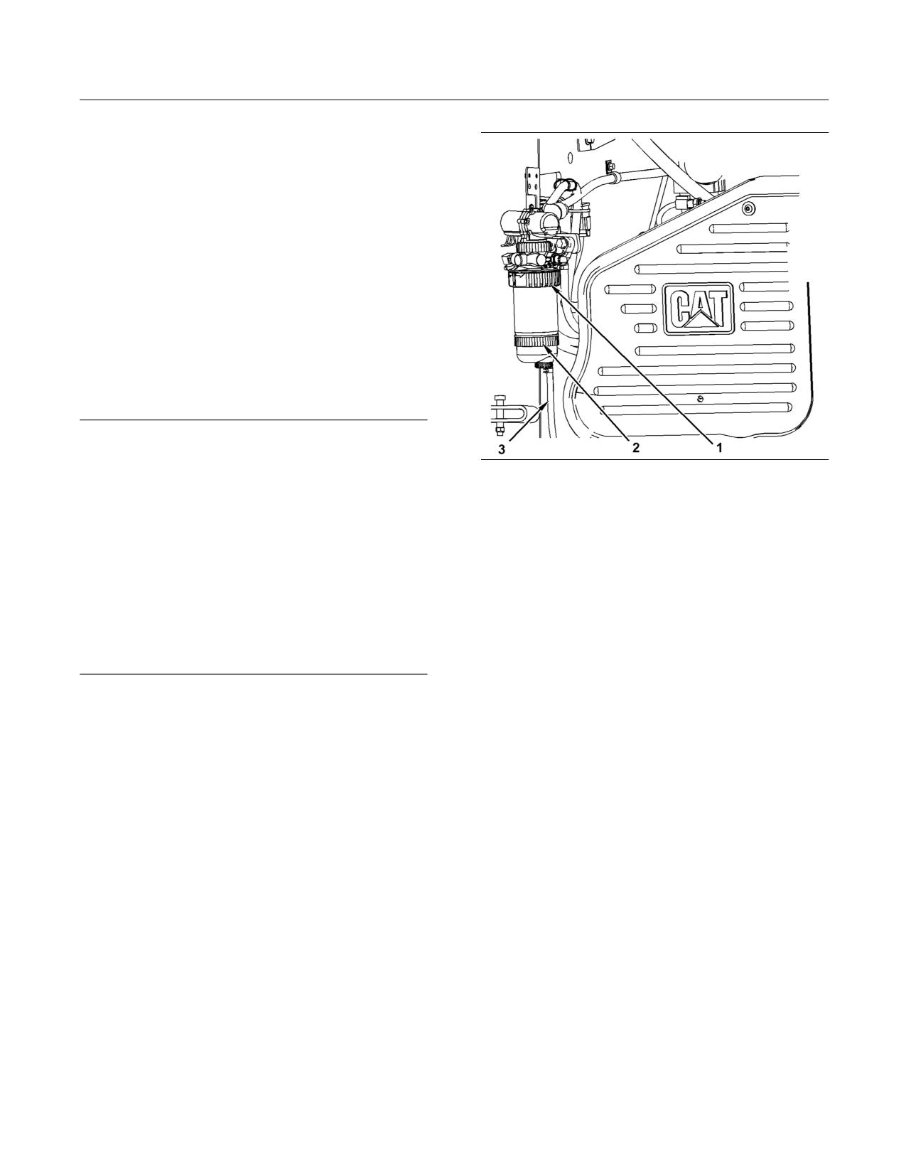
SEBU8407-06
153
Maintenance Section
Fuel System Primary Filter (Water Separator) Element - Replace
3. Tighten the drain valve by hand. Do not tighten
the drain valve with a tool. Damage to the valve or
to the seals may occur.
4. Close the engine access door.
5. Dispose of the water and sediment according to
local regulations.
i02520124
Fuel System Primary Filter
(Water Separator) Element -
Replace
SMCS Code: 1260-510-FQ; 1263-510-FQ
NOTICE
Care must be taken to ensure that fluids are contained
during performance of inspection, maintenance, test-
g01264527
Illustration 153
ing, adjusting and repair of the product. Be prepared to
The Fuel Filter/Water Separator is located on the left side of the
collect the fluid with suitable containers before open-
engine compartment.
ing any compartment or disassembling any compo-
nent containing fluids.
2. Open the drain on the fuel filter/water separator
(3). Allow the water and fuel to drain into a suitable
Refer to Special Publication, NENG2500, “Caterpillar
container.
Dealer Service Tool Catalog” for tools and supplies
suitable to collect and contain fluids on Caterpillar
3. Close the drain valve by hand. Do not tighten the
products.
drain valve with a tool. Damage to the valve or
to the seals may occur.
Dispose of all fluids according to local regulations and
mandates.
4. Support the fuel filter/water separator and rotate
the locking ring (1) counterclockwise. Remove the
Note: This unit has a dual purpose. The element
fuel filter/water separator.
serves as a water separator and a fuel filter.
5. Rotate the locking ring (2) counterclockwise.
1. Open the engine access door. Refer to Operation
Remove the bowl assembly.
and Maintenance Manual, “Access Doors and
Covers”.
6. Clean the mounting base for the fuel filter/water
separator.
7. Clean the bowl assembly for the fuel/water
separator.
8. Install the bowl assembly onto the new fuel/water
separator and rotate the locking ring clockwise.
9. Install the new fuel filter/water separator onto the
mounting base. Rotate the locking ring clockwise
in order to fasten the fuel filter/water separator to
the mounting base.
10. Prime the fuel system in order to fill the fuel
filter/water separator with fuel. Refer to Operation
and Maintenance Manual, “Fuel System Priming
Pump - Operate”.
11. Close the engine access door.
154
SEBU8407-06
Maintenance Section
Fuel System Priming Pump - Operate
i04728809
Fuel System Priming Pump -
Operate
SMCS Code: 1258-548
This machine is equipped with a fuel transfer pump
that is electric. Two examples that may cause the fuel
system to lose prime are listed here:
• The machine runs out of fuel.
• The Fuel System Filter/Water Separator Element
is replaced.
g00104238
Illustration 154
Follow the steps below in order to prime the fuel
2. Inspect the cap. Replace the cap if the cap is
system.
damaged.
1. Ensure that the engine start switch is in the OFF
3. Wash the fuel cap in a clean, nonflammable
position. Turn the engine start switch to the ON
solvent and dry the fuel cap.
position.
4. Put a light coating of fuel on the cap gasket.
Note: Do not start the engine. This operation only
starts the fuel pump. The pump will run approximately
5. Install the fuel cap.
1 minute.
2. The Primary Fuel Filter is located in the left side of
i02418544
the engine compartment.
Fuel Tank Water and Sediment
3. Examine the clear bowl. The bowl must contain
- Drain
only fuel. If the bowl is not full of fuel, repeat Steps
1 and 2.
SMCS Code: 1273-543-M&S
4. Attempt to start the engine. If the engine starts
NOTICE
and the engine runs rough or the engine misfires,
Care must be taken to ensure that fluids are contained
operate the engine at low idle until the engine
during performance of inspection, maintenance, test-
runs smoothly.
ing, adjusting and repair of the product. Be prepared to
collect the fluid with suitable containers before open-
Note: If the engine fails to start or if the engine
ing any compartment or disassembling any compo-
continues to misfire or smoke, stop the engine and
nent containing fluids.
repeat the procedure. If the problem persists after
repeating the procedure, consult your Cat dealer.
Refer to Special Publication, NENG2500, “Caterpillar
Dealer Service Tool Catalog” for tools and supplies
Note: Do not open any high pressure lines in order
suitable to collect and contain fluids on Caterpillar
to bleed air from the fuel system.
products.
i01819309
Dispose of all fluids according to local regulations and
mandates.
Fuel Tank Cap - Clean
Note: Drain the water and the sediment from the fuel
SMCS Code: 1273-070-Z2
tank when the tank is almost empty.
1. Remove the fuel cap.
1. Slowly remove the fuel tank cap in order to allow
the tank to vent while you drain the tank.
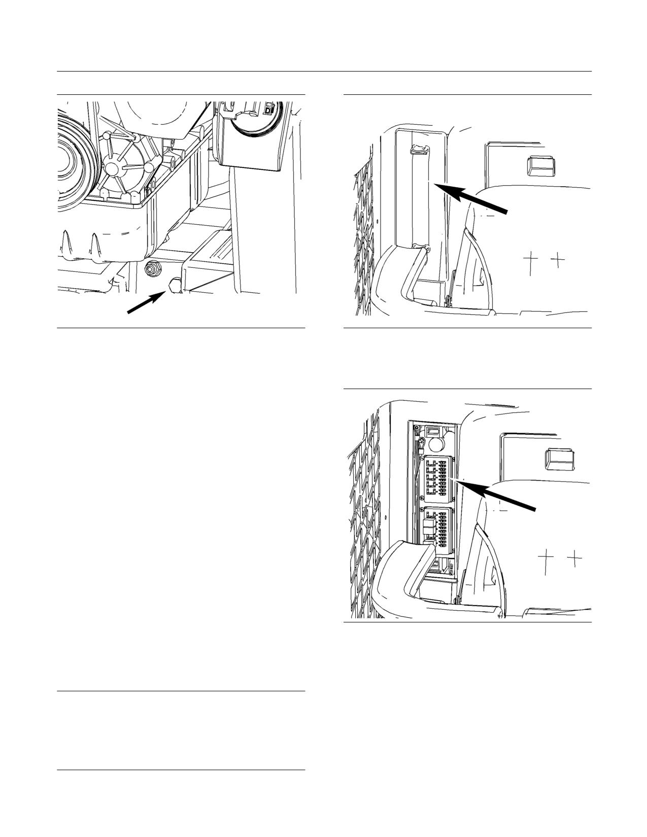
SEBU8407-06
155
Maintenance Section
Fuses - Replace
g01209601
g01287527
Illustration 155
Illustration 156
2. The fuel tank drain plug is located on the bottom
The fuse panel is located behind the seat on the right
of the fuel tank in the engine compartment on the
side.
right side of the machine. Remove the plug.
3. Allow the water and the sediment to drain into a
suitable container.
4. Install the fuel tank drain plug.
Note: Apply 5P-3413 Pipe Sealant to the threads on
the drain plug.
5. Install the fuel tank cap.
i02417559
Fuses - Replace
SMCS Code: 1417-510; 1417; 7528
Fuses
Fuses - Fuses protect the electrical system from
g01210555
Illustration 157
damage that is caused by overloaded circuits.
Replace the fuse if the element separates. If the
Remove the cover in order to access the fuse panel.
element of a new fuse separates, check the circuit.
Repair the circuit, if necessary.
NOTICE
Replace the fuses with the same type and size only.
Otherwise, electrical damage can result.
If it is necessary to replace fuses frequently, an electri-
cal problem may exist. Contact your Caterpillar dealer
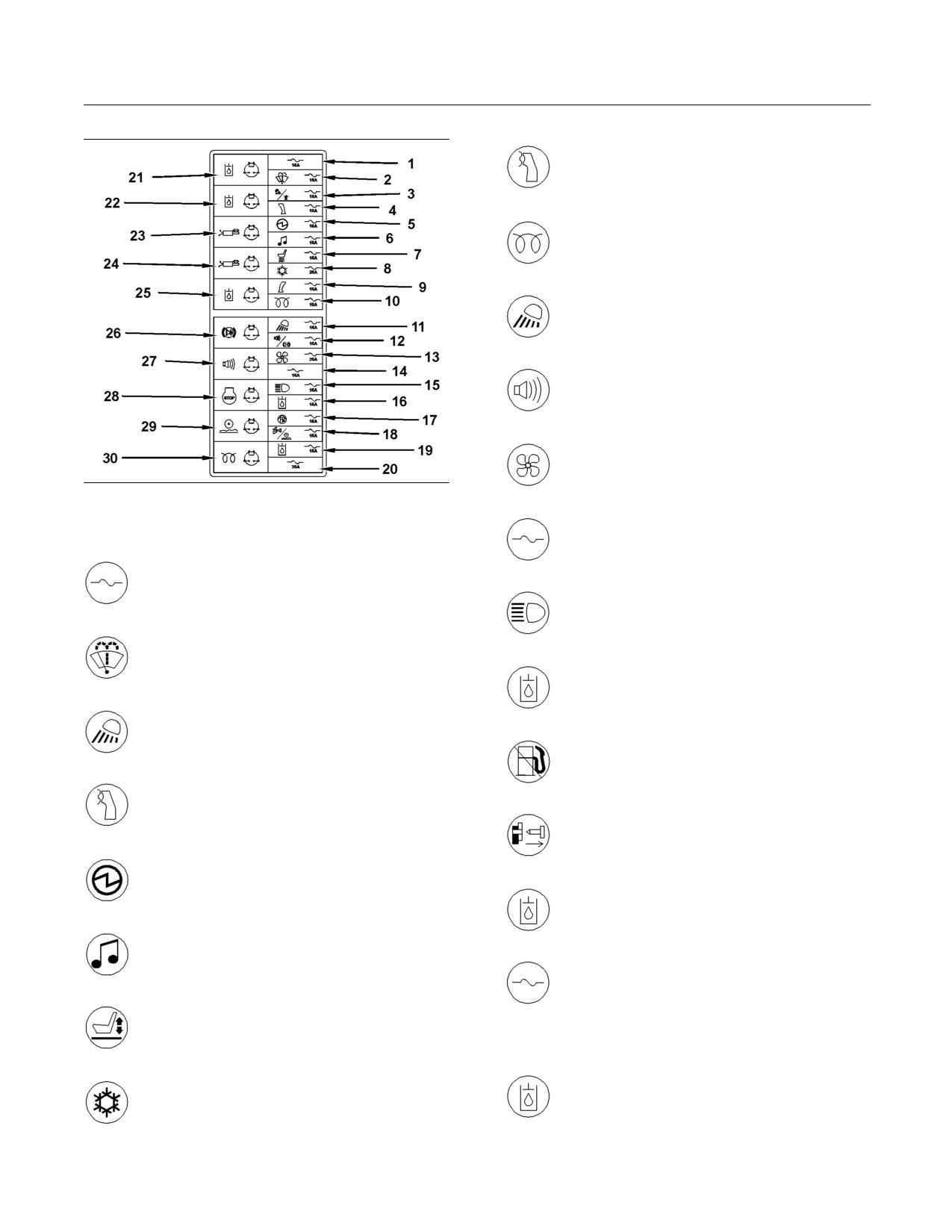
156
SEBU8407-06
Maintenance Section
Fuses - Replace
9 - Left Joystick
10 - Cold Start
11 - Rear Work Lights
12 - Backup Alarm and Brake Lights
13 - HVAC Blower Fan
g01262480
Illustration 158
14 - Spare
The following is a list of the fuses in the panel:
1 - Spare
15 - Headlights
2 - Wiper
16 - Hydraulic Solenoid
3 - Front Work Lights and Beacon
17 - Fuel Shutoff and Secondary Engine
Shutoff
4 - Right Joystick
18 - Hydraulic Quick Coupler
5 - 12 volt power socket
19 - Hydraulic Solenoid
6 - Radio
20 - Spare
7 - Solenoid for the Compressor
Solenoids
21 - Auxiliary Electrical Control “AUX6(C1)”
8 - Air Conditioner
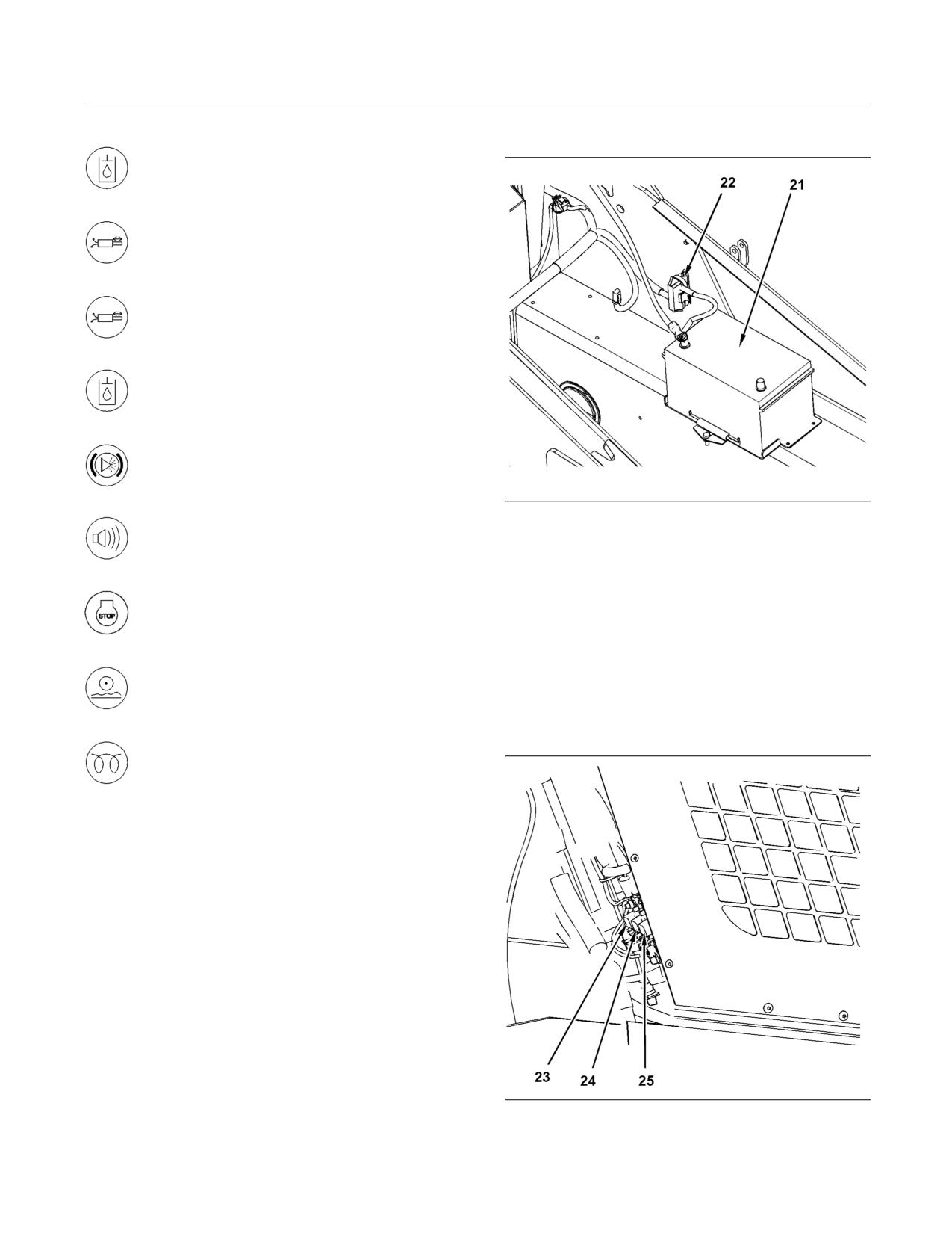
SEBU8407-06
157
Maintenance Section
Fuses - Replace
Main Fuse
22 - Auxiliary Electrical Control “AUX5(C2)”
23 - Secondary Auxiliary Electrical Control
“(C+)”
24 - Secondary Auxiliary Electrical Control
“(C-)”
25 - Auxiliary Electrical Control “AUX7”
26 - Stop Lamp
g01279310
Illustration 159
27 - Backup Alarm
(21) Battery
(22) Main fuse
The main fuse (22) is located behind the battery (21)
28 - Fuel Shutoff
on the left side of the machine under the cab. This is
a 105 amp fuse. You must disconnect the negative
battery cable before you replace this fuse.
29 - Self-Level and Ride Control
Fuse panel behind cab
There is an additional fuse panel behind the cab on
the right side of the machine.
30 - Glow Plugs
g01279419
Illustration 160
(23) First Pair
(24) Second Pair
(25) Third Pair
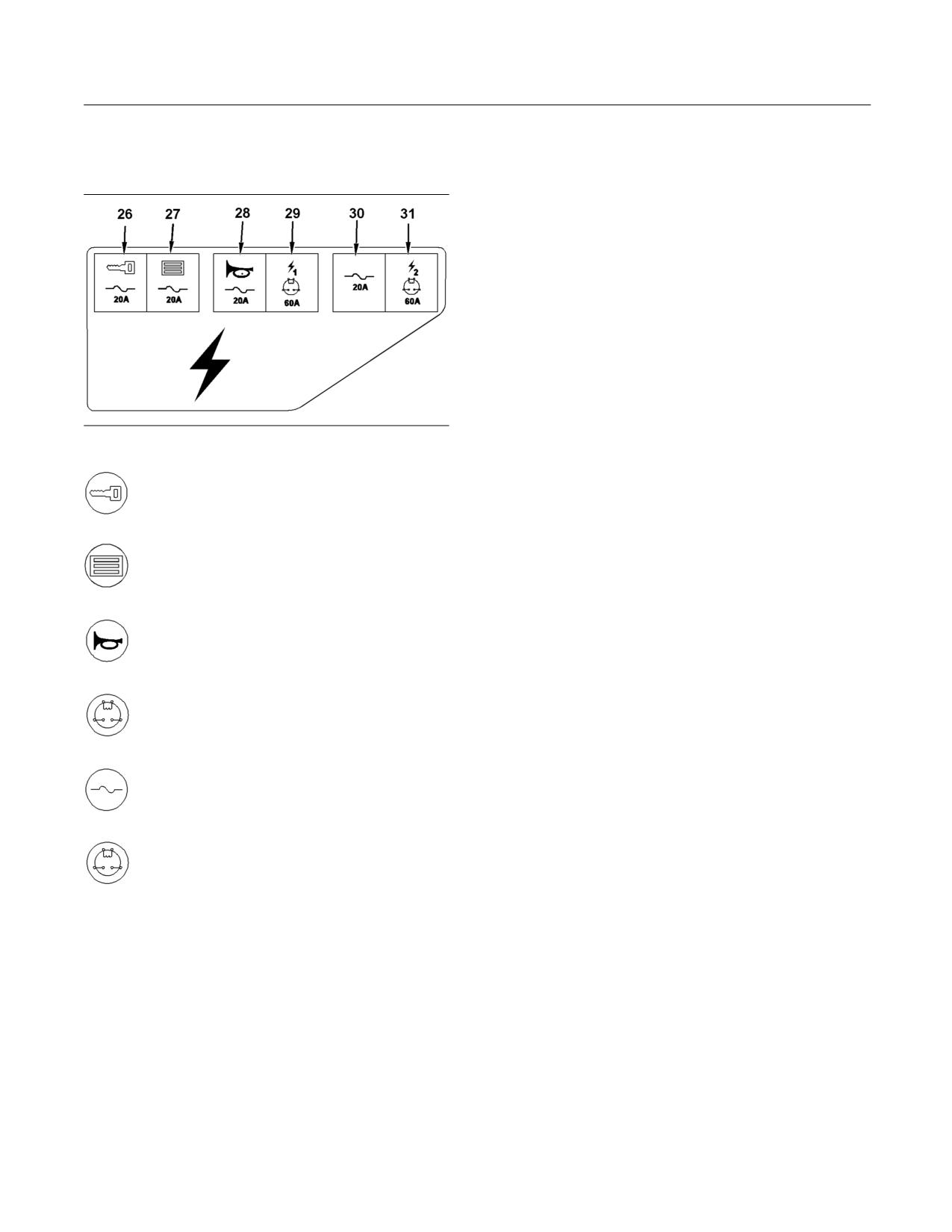
158
SEBU8407-06
Maintenance Section
Hydraulic System Oil - Change
This panel has 6 fuses. In order to change these
i03741203
fuses, push up on the locking tab on the fuse cover.
Hydraulic System Oil - Change
Pull the cover away from the back of the cab.
SMCS Code: 5095-044
Selection of the Oil Change Interval
Your machine may be able to use a 4000 hour
interval for the hydraulic oil. The hydraulic oil is in
the system that is not integral to the service brakes,
the clutches, the final drives, or the differentials.
The standard change interval is 2000 hours. The oil
should be monitored during intervals of 500 hours.
The extended 4000 hour interval can be used if the
following criteria are met.
g01279483
HYDO Advanced 10
Illustration 161
Cat HYDO Advanced 10 is the preferred oil for use in
26 - Ignition switch
most Caterpillar machine hydraulic and hydrostatic
transmission systems when ambient temperature
is between -20 °C (-4 °F) and 40 °C (104 °F). Cat
HYDO Advanced 10 has an SAE viscosity grade of
27 - ECM
10W. Cat HYDO Advanced 10 has a 50% increase
in the standard oil drain interval (up to 3000 hours)
for machine hydraulic systems over second and third
choice oils when you follow the maintenance interval
28 - Horn
schedule for oil filter changes and for oil sampling that
is stated in the Operation and Maintenance Manual.
6000 hour oil drain intervals are possible when using
S·O·S Services oil analysis. When you switch to Cat
HYDO Advanced 10, cross contamination with the
29 - Main power relay 1
previous oil should be kept to less than 10%. Consult
your Cat dealer for details about the benefits from
the improved performance designed into Cat HYDO
Advanced 10.
30 - Miscellaneous cab accessories
Oil Filters
Caterpillar oil filters are recommended. The interval
31 - Main power relay 2
for changing the oil filter should be 500 hours.
Oil
The 6000 hour interval for changing the oil is specific
to HYDO Advance 10.
The 4000 hour interval for changing the oil is for the
following oil types.
• Caterpillar Hydraulic Oil (HYDO)
• Caterpillar Transmission and Drive Train Oil
(TDTO)
• Caterpillar TDTO-TMS
• Caterpillar Diesel Engine Oil
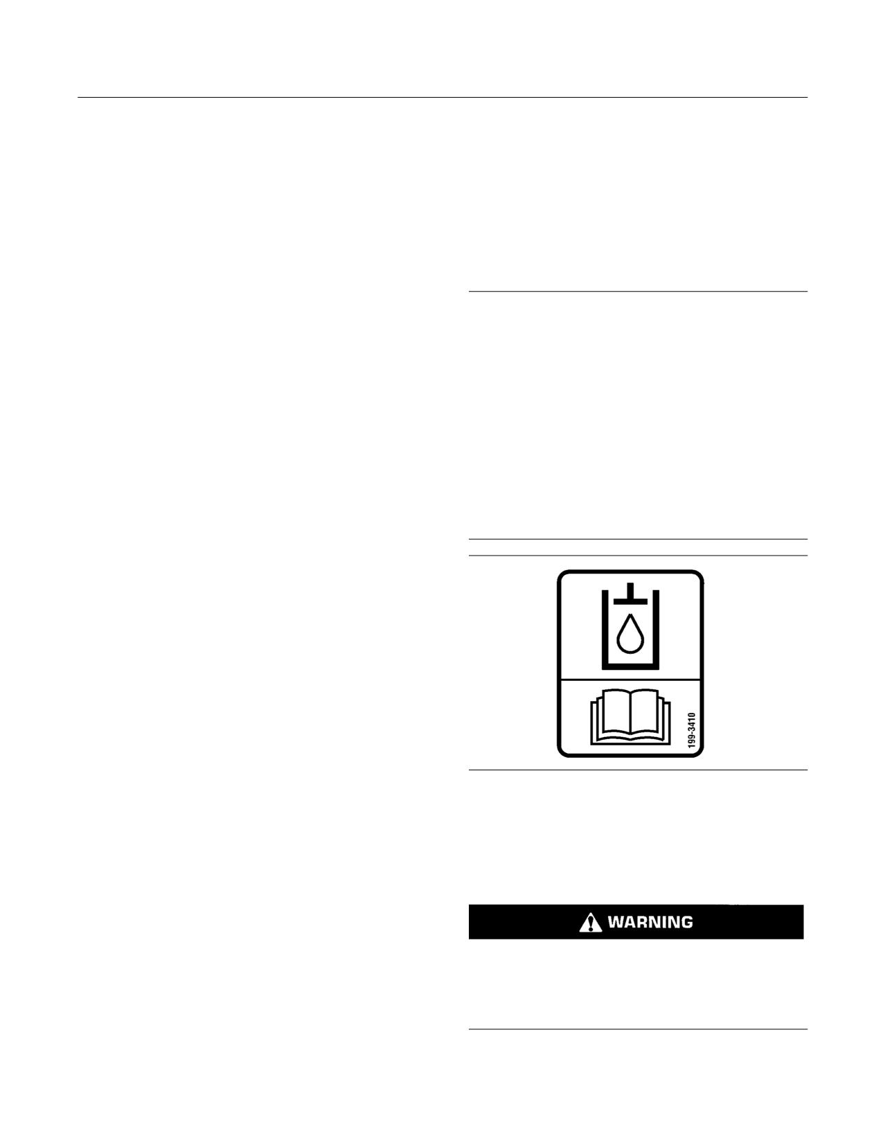
SEBU8407-06
159
Maintenance Section
Hydraulic System Oil - Change
• Caterpillar Biodegradable Hydraulic Oils (HEES)
• The allowable level of oxidation is 40 percent (0.12
Abs units).
• Caterpillar Multipurpose Tractor Oil (MTO)
•
The kinematic viscosity of 100 °C (212 °F) oil
• Heavy-duty diesel engine oils with a minimum zinc
should not exceed a change of more than 2 cSt
content of 900 ppm
from new oil.
If Caterpillar oils cannot be used, use heavy-duty oils
Procedure for Changing the
with the following classification: Caterpillar ECF-1,
API CG-4, API CF, and TO-4. These oils must have
Hydraulic Oil
a minimum zinc additive of 0.09 percent (900 ppm).
NOTICE
Note: Industrial hydraulic oils are not recommended
Care must be taken to ensure that fluids are contained
in Caterpillar hydraulic systems.
during performance of inspection, maintenance, test-
ing, adjusting and repair of the product. Be prepared to
Monitoring the Condition of the Oil
collect the fluid with suitable containers before open-
ing any compartment or disassembling any compo-
The oil should be monitored during intervals of 500
nent containing fluids.
hours. Caterpillar's standard SOS Fluids Analysis or
an equivalent oil sampling program should be used.
Refer to Special Publication, NENG2500, “Caterpillar
Dealer Service Tool Catalog” for tools and supplies
The current guidelines for cleanliness of the oil
suitable to collect and contain fluids on Caterpillar
should be observed. Refer to “Measured Data”.
products.
If an oil sampling program is not available, the
Dispose of all fluids according to local regulations and
standard 2000 oil change interval should be used.
mandates.
Measured Data
The following information should be monitored
through sampling of the oil:
• Significant changes in wear metals should be
monitored. These metals include iron, copper,
chromium, lead, aluminum, and tin.
• Significant changes in the following additives
should be monitored: zinc, calcium, magnesium,
and phosphorus.
• Contaminants should not be present. These
g00956818
contaminants include fuel and antifreeze. Water
Illustration 162
content should be .5 percent or less.
Note: This film is located near the hydraulic filler
• The silicon level should not exceed 15 parts per
cap on machines that are filled with arctic oil.
million for new oil. The particle counts should be
monitored.
Operate the machine for a few minutes in order to
warm the hydraulic system oil.
• The recommended level of cleanliness for
Caterpillar machines that are operated in the field
is ISO 18/15 or cleaner. The cleanliness should be
monitored by particle count analysis. The levels
Personal injury or death can result without releas-
of contamination should not exceed the normal
ing all of the hydraulic pressure.
by more than two ISO codes. Action should be
taken in order to determine the cause of the
Release all the pressure from the hydraulic sys-
contamination. The system should be returned to
tem before any lines are disconnected.
the original levels of contamination.
• There should not be significant changes in sodium,
silicon, copper, and potassium.
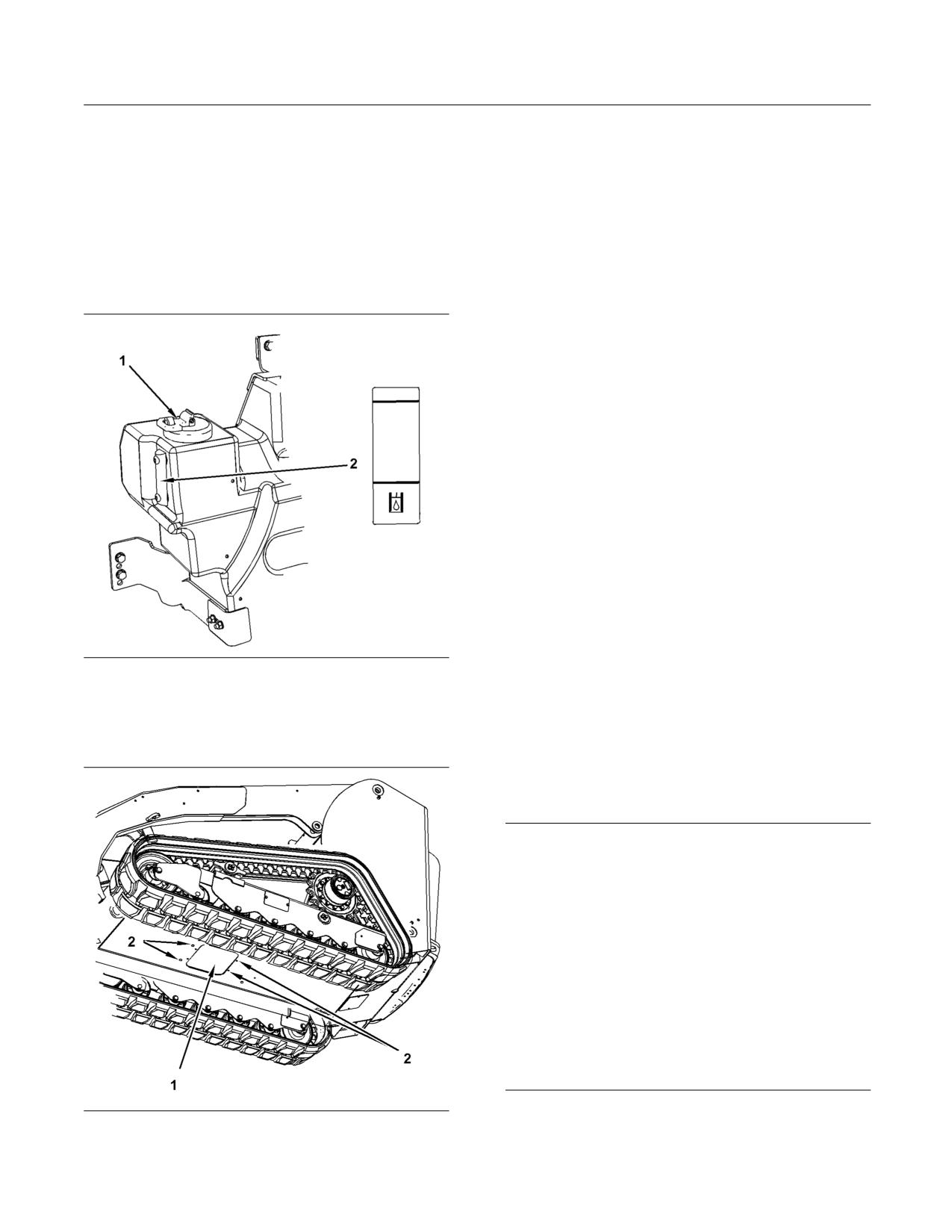
160
SEBU8407-06
Maintenance Section
Hydraulic System Oil Filter - Replace
The machine should be on level ground. Lower the
2. Remove the access panel in the belly guard
bucket to the ground and apply slight downward
underneath the machine.
pressure. Engage the parking brake and stop the
engine. Keep the armrest lowered. Turn the engine
3. The hose is located on the right side. Pull the drain
start switch key to the ON position. Push the parking
hose through the access hole in the belly guard.
brake switch. Move all of the joystick controls while
Remove the plug from the end of the drain hose.
you press several times on each side of the auxiliary
Drain the oil into a suitable container.
hydraulic control (if equipped) in order to relieve
hydraulic pressure. Move the engine start switch key
4. Install the drain plug into the drain hose. Tighten
to the OFF position.
to 22 ± 3 N·m (16 ± 2 lb ft). Pull the drain hose
back into the machine.
5. Change the hydraulic system filter. Refer to
Operation and Maintenance Manual, “Hydraulic
System Oil Filter - Change”.
6. Fill the hydraulic system oil tank. Refer to
Operation and Maintenance Manual, “Lubricant
Viscosities” and Operation and Maintenance
Manual, “Capacities (Refill)”.
7. Maintain the hydraulic oil level approximately in
the middle of the sight gauge (2).
Check the oil level with the loader arms in the fully
lowered position.
Note: The oil must be free of bubbles. If bubbles are
present in the oil, air is entering the hydraulic system.
Inspect the suction hoses and hose clamps.
g01280697
8. Install the hydraulic tank filler cap.
Illustration 163
(1) Hydraulic Tank Filler Cap
(2) Sight Gauge
i02743340
1. Remove the hydraulic tank filler cap (1).
Hydraulic System Oil Filter -
Replace
SMCS Code: 5068-510
NOTICE
Care must be taken to ensure that fluids are contained
during performance of inspection, maintenance, test-
ing, adjusting and repair of the product. Be prepared to
collect the fluid with suitable containers before open-
ing any compartment or disassembling any compo-
nent containing fluids.
Refer to Special Publication, NENG2500, “Caterpillar
Dealer Service Tool Catalog” for tools and supplies
suitable to collect and contain fluids on Caterpillar
products.
Dispose of all fluids according to local regulations and
mandates.
g01451462
The hydraulic oil filter is located in the engine
Illustration 164
compartment.
(1) Access panel
(2) Retaining bolts
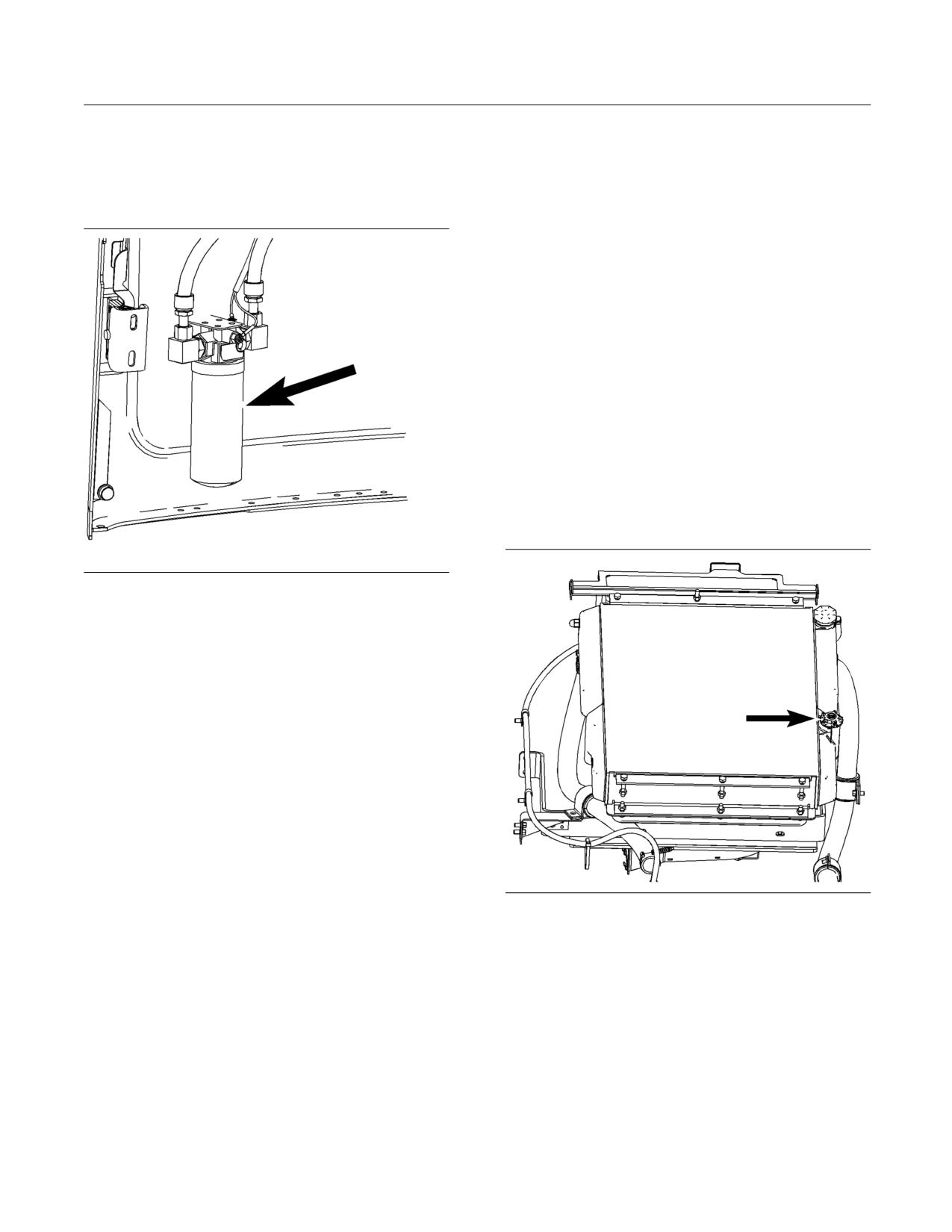
SEBU8407-06
161
Maintenance Section
Hydraulic System Oil Level - Check
1. Open the engine access door. Refer to Operation
Note: You may need to use a Caterpillar strap
and Maintenance Manual, “Access Doors and
wrench, or another suitable tool, in order to turn
Covers”.
the filter to the amount that is required for final
installation. Make sure that the installation tool does
2. Remove the hydraulic tank filler cap.
not damage the filter.
8. Maintain the hydraulic oil level to the middle of the
sight gauge. Refer to Operation and Maintenance
Manual, “Hydraulic System Oil Level - Check”. Do
not overfill the hydraulic tank.
9. Inspect the gasket on the hydraulic tank filler cap
for damage. Replace the hydraulic tank filler cap,
if necessary. Install the hydraulic tank filler cap.
10. Close the engine access door.
i02418557
Hydraulic System Oil Level -
Check
SMCS Code: 5095-535-FLV
g01209326
Illustration 165
The hydraulic filter is located on the rear door.
3. Remove the filter with a strap type wrench.
Note: Place a suitable nonconductive container
under the hydraulic oil filter. Use this container in
order to catch any oil that may spill from the filter or
the filter element mounting base.
4. Clean the filter element mounting base. Remove
any part of the filter element gasket that remains
on the filter element mounting base.
5. Apply a light coat of oil to the gasket of the new
filter element gasket.
6. Install a newfilter hand tight until the seal of the
filter contacts the base. Note the position of the
g01306294
Illustration 166
index marks on the filter in relation to a fixed point
Filler for adding hydraulic oil
on the filter base.
Note: There are rotation index marks on the filter
that are spaced 90 degrees or 1/4 of a turn away
from each other. When you tighten the filter, use the
rotation index marks as a guide.
7. Tighten the filter according to the instructions
that are printed on the filter. Use the index marks
as a guide. For non-Caterpillar filters, use the
instructions that are provided with the filter.
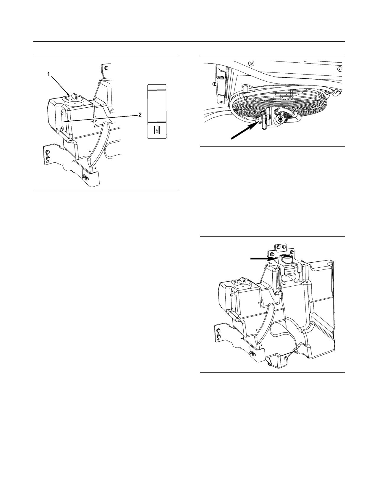
162
SEBU8407-06
Maintenance Section
Hydraulic System Oil Sample - Obtain
g01280271
Illustration 168
The sampling port for the hydraulic oil is located on
the fan motor.
i02557991
g01280697
Illustration 167
Hydraulic Tank Breather -
(2) Sight gauge on right side of tank
Replace
1. Park the machine on level ground.
SMCS Code: 5050-510-BRE; 5056-510-BRE
2. Lower the work tool to the ground. Turn off the
engine.
3. Wait for about five minutes before checking the
level of the hydraulic oil.
4. Use the hydraulic oil filler on the radiator in order
to top off the hydraulic oil.
5. Maintain the oil level to the middle of the two lines
on the sight gauge. Do not overfill the hydraulic
tank.
i02920120
Hydraulic System Oil Sample
- Obtain
SMCS Code: 5050-008; 7542-008
Open the rear access door. Refer to Operation and
g01280304
Illustration 169
Maintenance Manual, “Access Doors and Covers” for
information about the rear door.
The breather for the hydraulic tank is located on the
top of the hydraulic tank.
Raise the radiator. Refer to Operation and
Maintenance Manual, “Radiator Tilting” for
1. Raise the cab. Refer to Operation and
information about the radiator.
Maintenance Manual, “Cab Tilting” for the
procedure to raise the cab.
2. Remove the breather.
3. Install the new breather and tighten to 20 ± 3 N·m
(15 ± 2 lb ft).
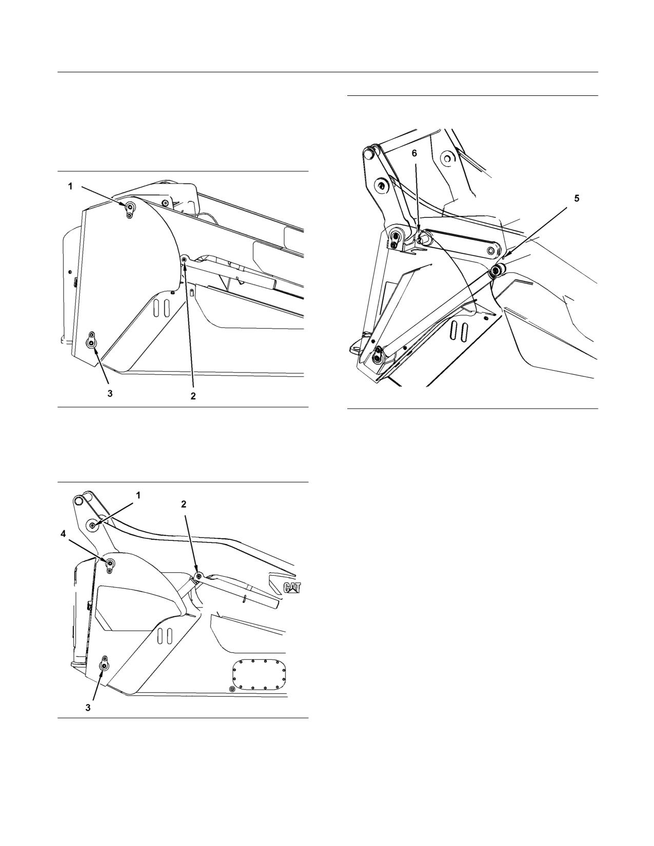
SEBU8407-06
163
Maintenance Section
Lift Arm and Cylinder Linkage - Lubricate
i02418559
Lift Arm and Cylinder Linkage
- Lubricate
SMCS Code: 5102-086-BD; 6107-086-BD
g01210414
g01210416
Illustration 170
Illustration 172
Radial Lift
The Link Arm is located behind the loader arm.
(1) Lift Arm Pivot
(5) Mounting for Link Pin
(2) Lift Cylinder Rod End
(6) Rear of Link Arm
(3) Head End Fitting
Apply lubricant to all the grease fittings on one side.
Repeat the process for the opposite side of the
machine.
i02919914
Lower Machine Frame - Clean
SMCS Code: 7050-070
1. Tilt the cab upward. Refer to Operation and
Maintenance Manual, “Cab Tilting”.
g01210415
Illustration 171
Vertical Lift
(1) Lift Arm Pivot
(2) Lift Cylinder Rod End
(3) Head End Fitting
(4) Link Arm
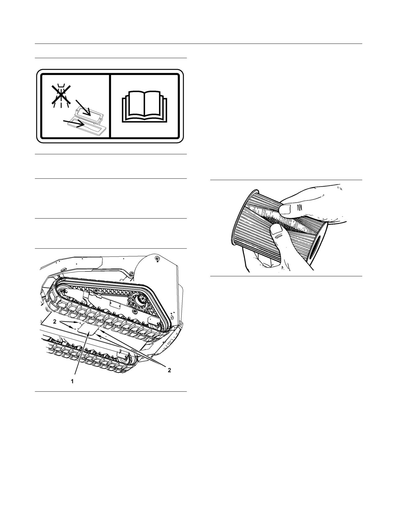
164
SEBU8407-06
Maintenance Section
Oil Filter - Inspect
6. Remove any debris or dirt from the inside of the
frame.
7. Reinstall the access panel.
8. Remove the cover from the ventilation ducts.
9. Tilt the cab downward.
i02106227
Oil Filter - Inspect
SMCS Code: 1308-507; 3067-507; 5068-507
g01270620
Illustration 173
This film is located in the air duct.
Inspect a Used Filter for Debris
NOTICE
Do not spray water or cleaning fluids into the venti-
lation ducts. Cover the opening in order to prevent
foreign material or fluid from entering the ventilation
ducts.
2. Seal the opening of the ventilation ducts with
plastic.
g00100013
Illustration 175
The element is shown with debris.
Use a filter cutter to cut the filter element open.
Spread apart the pleats and inspect the element for
metal and for other debris. An excessive amount of
debris in the filter element can indicate a possible
failure.
If metals are found in the filter element, a magnet can
be used to differentiate between ferrous metals and
nonferrous metals.
Ferrous metals can indicate wear on steel parts and
on cast iron parts.
g01451462
Illustration 174
Nonferrous metals can indicate wear on the
(1) Access panel
aluminum parts of the engine such as main bearings,
(2) Retaining bolts
rod bearings, or turbocharger bearings.
3. The access panel (1) is located in the frame
Small amounts of debris may be found in the filter
underneath the machine.
element. This could be caused by friction and by
normal wear. Consult your Caterpillar dealer in order
4. Remove the four retaining bolts (2).
to arrange for further analysis if an excessive amount
of debris is found.
5. Slide the panel forward or slide the panel rearward.
Pull the panel downward and remove the access
panel from the machine.
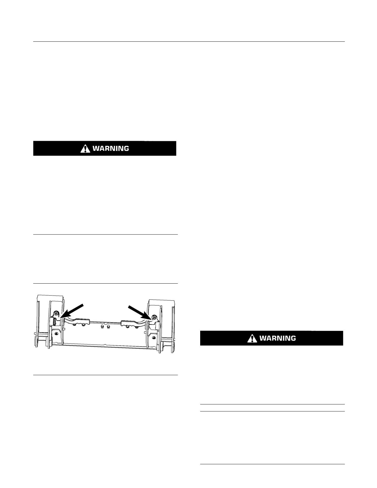
SEBU8407-06
165
Maintenance Section
Quick Coupler - Clean/Inspect
Using an oil filter element that is not recommended
5. Check the top edges of the quick coupler assembly
by Caterpillar can result in severe engine damage
for wear or for damage. Check the face of the
to engine bearings, to the crankshaft, and to other
quick coupler assembly for wear or for damage.
parts. This can result in larger particles in unfiltered
oil. The particles could enter the lubricating system
6. Inspect the components inside the quick coupler
and the particles could cause damage.
for the following problems:loose bolts, oil
leaks, broken parts, missing parts, and cracked
components
i02634143
7. Inspect the hydraulic lines and the hydraulic
Quick Coupler - Clean/Inspect
fittings for damage or for wear. Repair any worn
components or replace any worn components.
SMCS Code: 6129-040; 6129-070
Repair any leaking components.
8. Inspect the steel material of the quick coupler for
cracks.
Personal injury or death can result from improp-
erly checking for a leak.
Note: Perform all repairs before placing the quick
coupler back into operation.
Always use a board or cardboard when checking
for a leak. Escaping air or fluid under pressure,
i02575087
even a pin-hole size leak, can penetrate body tis-
sue causing serious injury, and possible death.
Radiator Core - Clean
If fluid is injected into your skin, it must be treated
SMCS Code: 1353-070-KO
immediately by a doctor familiar with this type of
injury.
The radiator is located at the rear of the machine
above the engine compartment.
Note: Do not weld on the quick coupler without
consulting your Caterpillar dealer.
Note: Adjust the frequency of cleaning according to
the effects of the operating environment. On models
1. Clean the quick coupler prior to inspection in order
272C and 297C, clean the aftercooler core when you
to properly inspect the quick coupler.
clean the radiator core.
1. Stop the engine. Open the engine access door.
Refer to Operation and Maintenance Manual,
“Access Doors and Covers”.
2. Tilt the radiator guard upward. Refer to Operation
and Maintenance Manual, “Radiator Tilting”.
Personal injury can result from air pressure.
Personal injury can result without following prop-
er procedure. When using pressure air, wear a pro-
g01322438
tective face shield and protective clothing.
Illustration 176
This is the back side of the quick coupler. The lift arm and the tilt
Maximum air pressure at the nozzle must be less
cylinder are removed for clarity.
than 205 kPa (30 psi) for cleaning purposes.
2. Tilt the quick coupler all the way forward in order
to clean the debris away from the pins.
NOTICE
When you are using compressed air or high pressure
3. Move the quick coupler levers. Ensure that the
water to clean the radiator fins, ensure that the air or
levers are not bent or broken.
water is directed parallel to the fins. If the compressed
air or high pressure water is not directed parallel to the
4. Make sure that the coupler pins extend through
radiator fins, the radiator fins could be bent or dam-
the bottom of the quick coupler assembly. Check
aged.
the pins for wear and check the pins for damage.
166
SEBU8407-06
Maintenance Section
Refrigerant Dryer - Replace
Note: Pressurized air is the preferred method for
i01968724
removing loose debris. Hold the nozzle approximately
Refrigerant Dryer - Replace
6 mm (0.25 inch) away from the fins. Slowly move the
air nozzle in a direction that is parallel with the tubes.
(If Equipped)
The air nozzle should point in the opposite direction
of the flow of the fan. This will remove debris that
SMCS Code: 7322-510
is between the tubes. Pressurized water may also
be used for cleaning. The maximum water pressure
for cleaning purposes must be less than 275 kPa
(40 psi). Use pressurized water in order to soften
Personal injury can result from contact with refrig-
mud. Use a degreaser and steam for removal of oil
erant.
and grease. Wash the core with detergent and hot
water. Thoroughly rinse the core with clean water.
Contact with refrigerant can cause frost bite. Keep
face and hands away to help prevent injury.
3. Clean the radiator core from the top toward the
fan.
Protective goggles must always be worn when re-
frigerant lines are opened, even if the gauges in-
Note: If parts of the cooling system appear to
dicate the system is empty of refrigerant.
be damaged or if parts of the cooling system
are repaired, a leak test is highly recommended.
Always use precaution when a fitting is removed.
Consult your Caterpillar dealer for the most current
Slowly loosen the fitting. If the system is still un-
information about the cooling system.
der pressure, release it slowly in a well ventilated
area.
4. After cleaning, start the engine and accelerate
the engine to high idle rpm. This will help in the
Personal injury or death can result from inhaling
removal of debris and drying of the core. Stop the
refrigerant through a lit cigarette.
engine. Use a light bulb behind the core in order
to inspect the core for cleanliness. Repeat the
Inhaling air conditioner refrigerant gas through a
cleaning, if necessary.
lit cigarette or other smoking method or inhaling
fumes released from a flame contacting air con-
5. Inspect the fins and tubes of the radiator core
ditioner refrigerant gas, can cause bodily harm or
for damage. Some fins and tubes may be worn
death.
from abrasive material that has passed through
the radiator core . Bent fins may be opened with a
Do not smoke when servicing air conditioners or
“comb”.
wherever refrigerant gas may be present.
NOTICE
Use a certified recovery and recycling cart to prop-
Do not clean a rotating fan with high pressure water.
erly remove the refrigerant from the air condition-
Fan blade failure can result.
ing system.
6. Remove any dirt or debris from the fan, the fan
hub, the oil cooler, the radiator guard and the fan
NOTICE
guard.
If the refrigerant system has been open to the outside
air (without being plugged) for more than 30 minutes,
Note: Dirt or debris on the cooling fan can cause an
the receiver-dryer must be replaced. Moisture will en-
imbalance.
ter an open refrigerant system and cause corrosion
which will lead to component failure.
7. Tilt the radiator guard downward.
Refer to Service Manual, SENR5664, “Air
8. Close the engine access door.
Conditioning and Heating R-134a For All Caterpillar
Machines” for the proper procedure to change the
receiver-dryer assembly and for the procedure to
reclaim the refrigerant gas.
Note: The receiver-dryer must also be replaced when
the air conditioning system is evacuated.
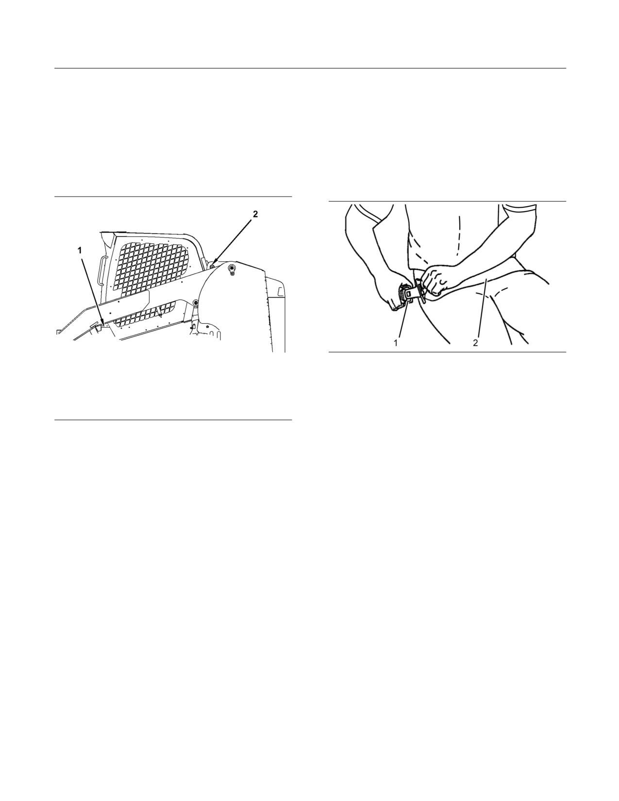
SEBU8407-06
167
Maintenance Section
Rollover Protective Structure (ROPS) and Falling Object Protective Structure (FOPS) - Inspect
i02418592
i04423622
Rollover Protective Structure
Seat Belt - Inspect
(ROPS) and Falling Object
SMCS Code: 7327-040
Protective Structure (FOPS) -
Always inspect the condition of the seat belt and the
Inspect
condition of the seat belt mounting hardware before
you operate the machine. Replace any parts that are
SMCS Code: 7323-040; 7325-040
damaged or worn before you operate the machine.
g02620101
Illustration 178
Typical example
Inspect buckle (1) for wear or for damage. If the
buckle is worn or damaged, replace the seat belt.
g01280181
Illustration 177
Inspect seat belt (2) for webbing that is worn or
frayed. Replace the seat belt if the webbing is worn
1. Inspect the ROPS for loose bolts. Tighten the
or frayed.
bolts (1) to the following torque 125 ± 20 N·m
(92 ± 15 lb ft). Check the hinge on the cab (2).
Inspect all seat belt mounting hardware for wear or
Check the ROPS and the FOPS for damaged
for damage. Replace any mounting hardware that
bolts or missing bolts. Replace any damaged bolts
is worn or damaged. Make sure that the mounting
or missing bolts with original equipment parts only.
bolts are tight.
2. Operate the machine on a rough surface. Replace
If your machine is equipped with a seat belt
the ROPS mounting supports if the ROPS
extension, also perform this inspection procedure for
emits a noise. Replace the ROPS mounting
the seat belt extension.
supports if the ROPS rattles. Refer to Operation
and Maintenance Manual, “Cab Tilting” for a
Contact your Cat dealer for the replacement of the
description of the mounting support.
seat belt and the mounting hardware.
Do not straighten the ROPS or the FOPS. Do
Note: The seat belt should be replaced within 3 years
not repair the ROPS or the FOPS by welding
of the date of installation. A date of installation label
reinforcement plates to the ROPS or the FOPS.
is attached to the seat belt retractor and buckle. If the
date of installation label is missing, replace belt within
Consult your Caterpillar dealer for repair of any
3 years from the year of manufacture as indicated
cracks in the ROPS or the FOPS.
on belt webbing label, buckle housing, or installation
tags (non-retractable belts).
Inspect the Flying Object Guard (if equipped) for
damage.
Consult your Caterpillar dealer for repair of any
cracks in the Flying Object Guard.
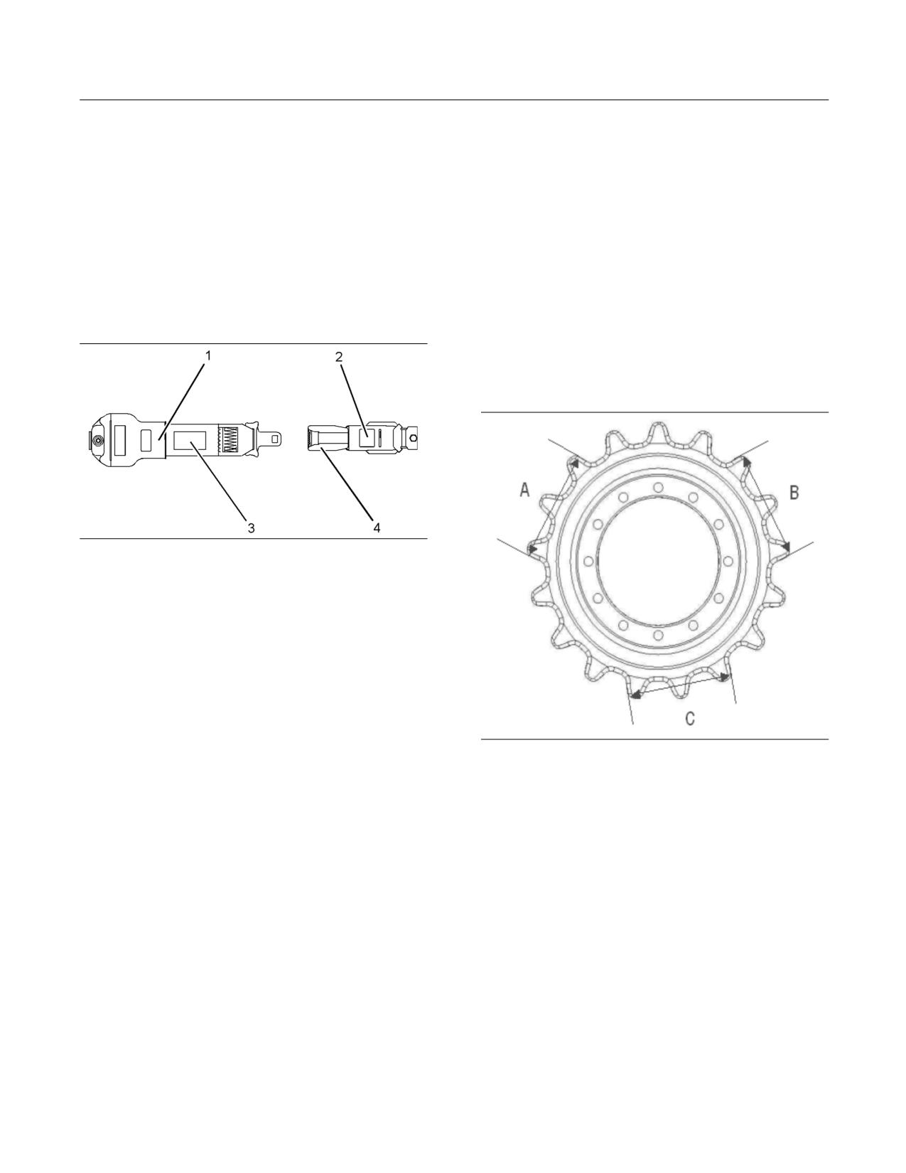
168
SEBU8407-06
Maintenance Section
Seat Belt - Replace
i04421974
i04782905
Seat Belt - Replace
Sprocket - Inspect
SMCS Code: 7327-510
SMCS Code: 4164-040
The seat belt should be replaced within 3 years of
Note: Operating the machine in conditions that are
the date of installation. A date of installation label is
muddy or sandy will cause accelerated wear on the
attached to the seat belt retractor and buckle. If the
sprocket and other undercarriage components. Clean
date of installation label is missing, replace belt within
the undercarriage of the machine daily in order to
3 years from the year of manufacture as indicated
maximize component life.
on belt webbing label, buckle housing, or installation
tags (non-retractable belts).
Sprocket Inspection for 279C,
289C, and 299C
Inspect
g01152685
Illustration 179
Typical Example
(1) Date of installation (retractor)
(2) Date of installation (buckle)
(3) Year of manufacture (tag) (fully extended Web)
(4) Year of manufacture (underside) (buckle)
Consult your Cat dealer for the replacement of the
seat belt and the mounting hardware.
Determine age of new seat belt before installing on
seat. A manufacture label is on belt webbing and
imprinted on belt buckle. Do not exceed install by
g02789983
Illustration 180
date on label.
1. Measure the sprocket teeth in three places as
Complete seat belt system should be installed with
shown in illustration 180.
new mounting hardware.
2. Calculate the average of the 3 measurements to
Date of installation labels should be marked and
determine the 50% wear limit.
affixed to the seat belt retractor and buckle.
3. If the average of 3 measurements is less than
Note: Date of installation labels should be
178 mm (7 inch), relocate the sprocket to the
permanently marked by punch (retractable belt) or
opposite side of the machine. Follow the steps
stamp (non-retractable belt).
in the “Relocate” section. If the average of 3
measurements is less than 165 mm (6.5 inch),
If your machine is equipped with a seat belt
then replace the sprocket. Follow the steps in the
extension, also perform this replacement procedure
“Replace” section.
for the seat belt extension.
Relocate
1. Remove the track on both sides of the machine.
2. Remove the sprocket on the left side of the
machine. Move the sprocket to the right side.
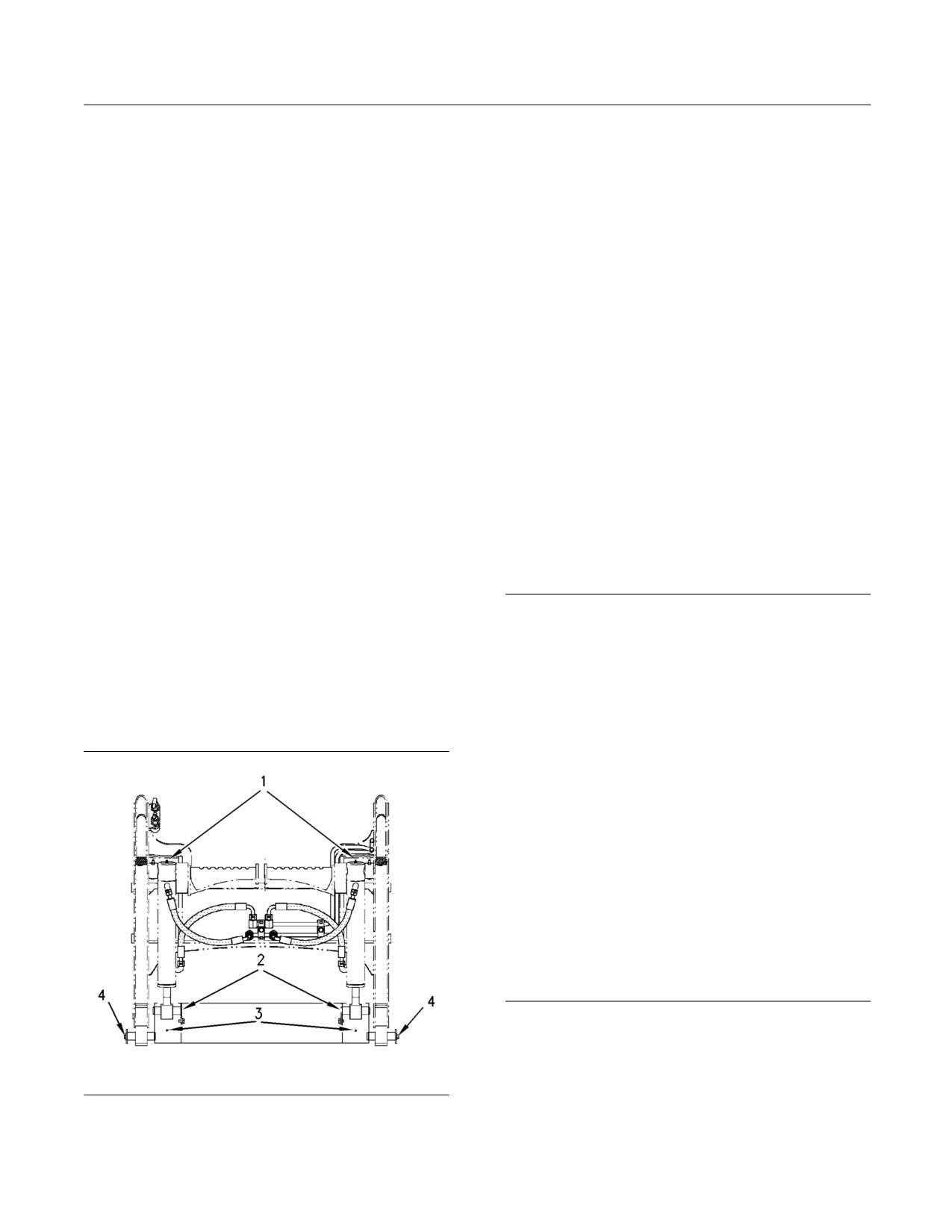
SEBU8407-06
169
Maintenance Section
Tilt Cylinder Bearings and Bucket Linkage Bearings - Lubricate
3. Remove the sprocket on the right side of the
Apply lubricant to the grease fittings (1) for the upper
machine. Move the sprocket to the left side.
bearings for the tilt cylinders.
4. Install the sprockets. Tighten the bolts to the
Apply lubricant to the grease fittings (2) for the lower
proper torque.
bearings for the tilt cylinders.
5. Install the track on both sides of the machine.
Apply lubricant to the grease fittings (3) for the
coupler engagement pins.
Replace
Apply lubricant to the grease fitting (4) for the pivot
pin of the quick coupler assembly.
1. Remove the track on both sides of the machine.
There are a total of 8 grease fittings.
2. Remove the sprocket on the left side of the
machine. Install the new sprocket.
i04748093
3. Tighten the bolts to the proper torque.
Track - Inspect/Adjust
4. Remove the sprocket on the right side of the
machine. Install the new sprocket.
SMCS Code: 4170-025; 4170-040
5. Tighten the bolts to the proper torque.
Periodic adjustment of the track tension is necessary
in order to avoid damage to the tracks. Maintaining
6. Install the track on both sides of the machine.
the tracks at the proper tension will maximize the
service life of the undercarriage components. The
undercarriage components include the final drive
i01878236
sprocket, idlers, rollers, and the track.
Tilt Cylinder Bearings and
NOTICE
Bucket Linkage Bearings -
Do not overtighten the tracks. Tracks that are too tight
Lubricate
can cause premature failure of the tracks. Tracks that
are too tight can cause power loss and bearing fail-
SMCS Code: 5104-086-BD; 6107-086-BD
ures.
Wipe all of the grease fittings before you apply
Tracks that are too loose increase the possibility of
lubricant.
the track derailing or the drive lugs mis-feeding on the
drive sprocket. In aggressive operating conditions, oc-
casional mis-feeding is normal. If consistent mis-feed-
ing is observed, ensure that the track tension is set to
the recommended specification. If the track tension is
set to the recommended specification and mis-feed-
ing is still observed, then your application may require
a tighter track tension. Increase the track tension until
consistent mis-feeding is no longer observed.
The intervals for track tension vary depending on the
following conditions: the machine application, the op-
erator, the soil conditions, the climate, and the condi-
tion of the undercarriage components. Operators are
responsible for basic visual inspections of the track
tension on a daily basis.
g00955895
Illustration 181
Note: Lubricate the fittings with the loader lift arms in
the fully lowered position.
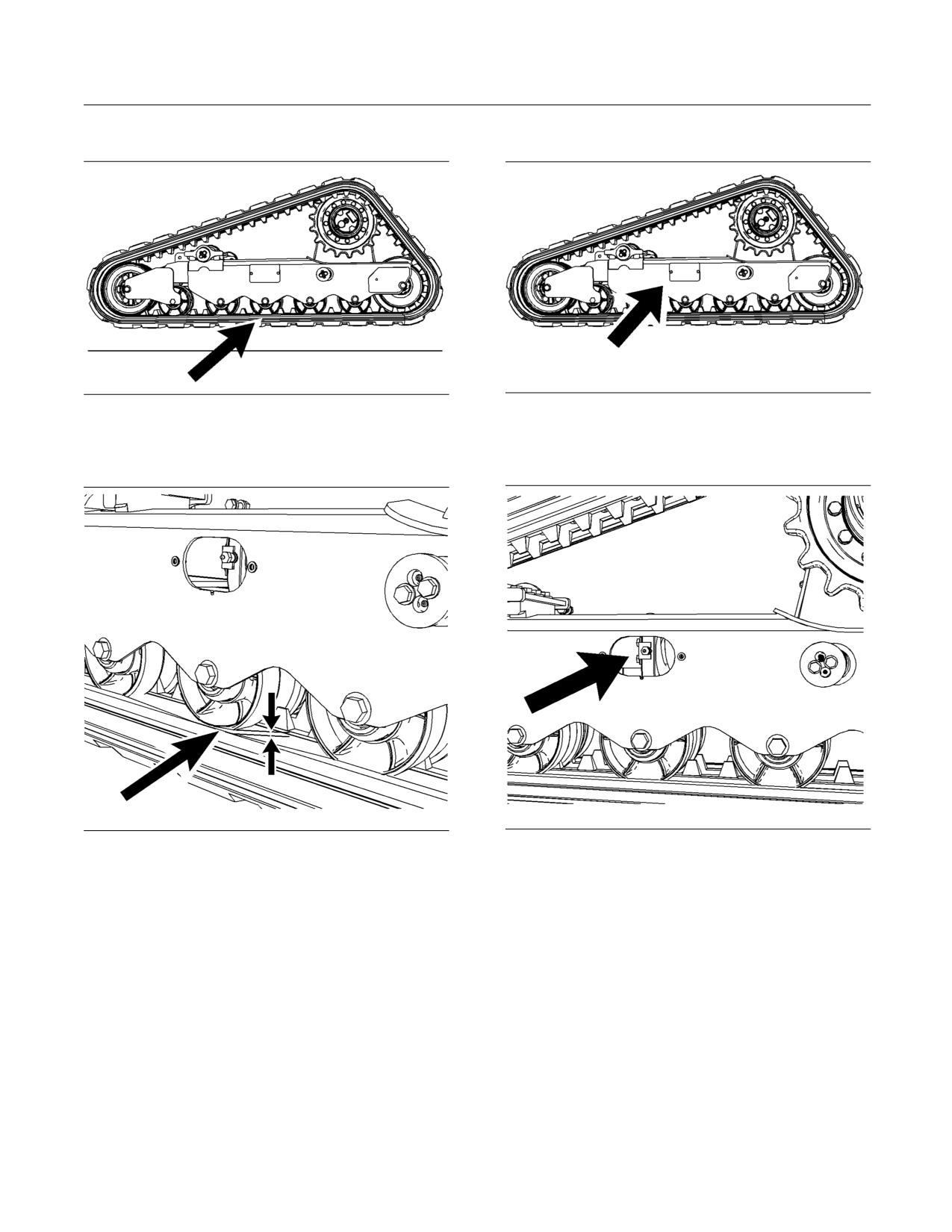
170
SEBU8407-06
Maintenance Section
Track - Inspect/Adjust
Inspect
Track Adjustment
g01450469
g01450599
Illustration 182
Illustration 184
Support the machine so that the track is a minimum
1. In order to adjust the track, remove the access
of 51 mm (2 inch) above the ground.
panel on the side of the undercarriage.
g01450565
g01450604
Illustration 183
Illustration 185
Measure the track sag at the middle track roller.
2. Pressurized grease in a cylinder is used in order
Measure the distance from the bottom surface of
to provide tension on the track. Use a grease gun
the flange on the roller to the inside top surface of
in order to apply grease to the grease fitting on the
the track. The minimum track sag should be 30 mm
cylinder. The track will be tightened.
(1.18 inch). The maximum track sag should be
40 mm (1.57 inch).
3. Recheck the track tension.
4. Replace the access panel when the 30 mm
(1.18 inch) sag is achieved.
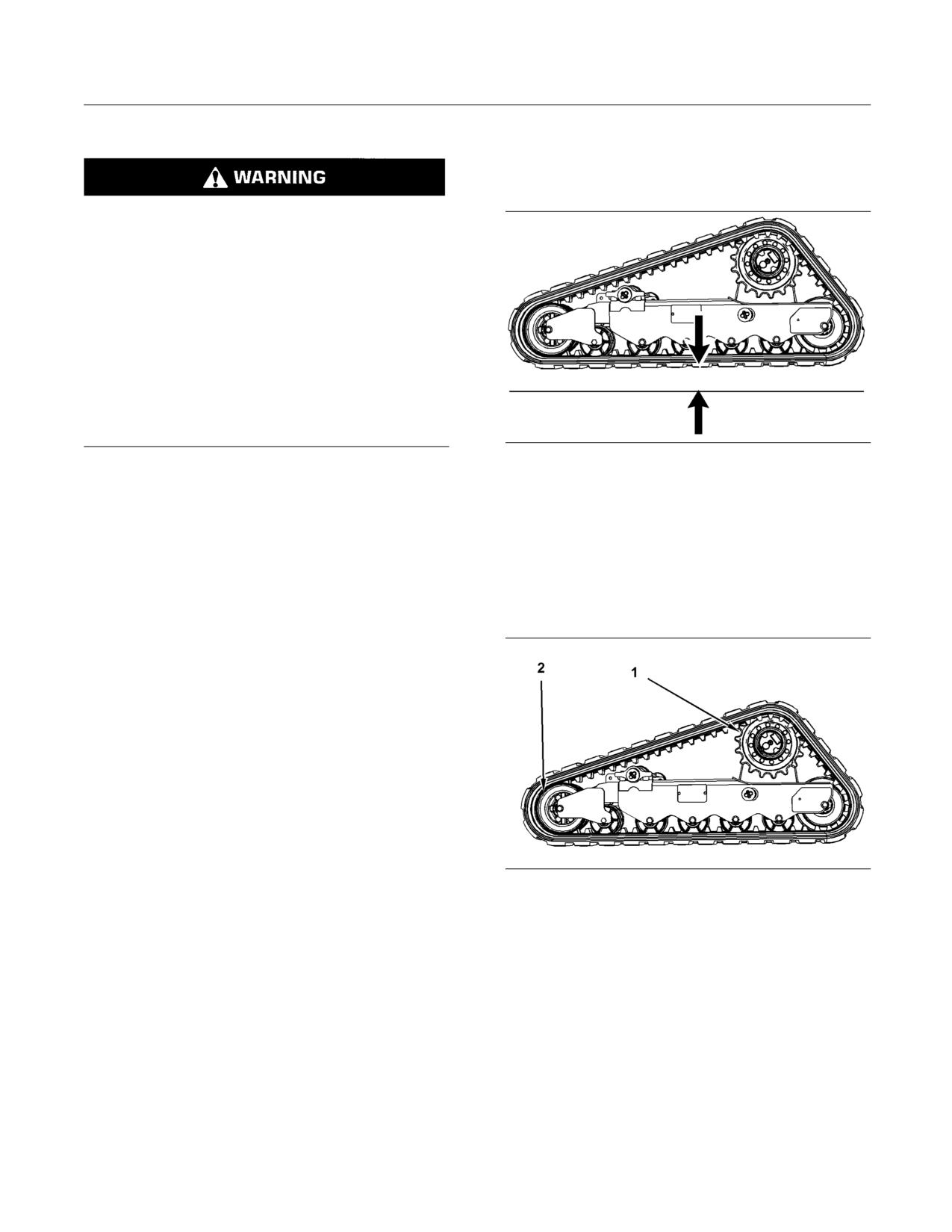
SEBU8407-06
171
Maintenance Section
Track - Remove/Replace
Detension the track
3. Raise the loader arms and install the brace
for the loader lift arm. Refer to Operation and
Maintenance Manual, “Loader Lift Arm Brace
Operation”.
Personal injury or death can result from grease
under pressure.
Grease coming out of the relief valve under pres-
sure can penetrate the body causing injury or
death.
Do not stand directly in front of the relief valve
to see if grease is escaping. Watch the track or
track adjustment cylinder to see if the track is be-
ing loosened.
If track does not loosen, close the relief valve and
consult your Cat dealer.
g01451611
Illustration 186
Note: Many operations for maintenance of the
undercarriage require the track to be loosened.
4. Use an appropriate floor jack in order to lift the
machine off the ground. Use appropriate jack
1. In order to detension the track, remove the access
stands in order to block up the machine. Raise
panel on the side of the undercarriage.
the machine until tracks are approximately 50 mm
(2.0 inch) (A) off the ground.
2. Loosen the grease fitting with a suitable device.
Loosen the grease fitting carefully until the track
5. Detension the track. Refer to Operation and
begins to loosen.
Maintenance Manual, “Track - Inspect/Adjust”.
Note: Catch the grease in a suitable container.
Dispose of the grease in accordance with all
applicable regulations.
Note: One turn should be sufficient. If grease
does not flow as expected, the lock plate can be
temporarily removed. The relief valve can be turned
further to allow for increased flow. Do not turn the
relief valve more than eight turns.
3. Tighten the grease fitting to a torque of 74 ± 14 N·m
(55 ± 10 lb ft) when the desired track tension is
reached.
g01450665
4. Replace the access panel.
Illustration 187
(1) Final Drive Sprocket
(2) Front idler wheel
i02916506
Note: The approximate weight of the track is 247 kg
Track - Remove/Replace
(545 lb).
SMCS Code: 4170-011; 4170-510
6. Use a suitable lifting device. Lift the track at middle
position between the front idler and the final drive
Removing the Track
sprocket until the front idler collapses fully.
1. Position the machine on firm, level ground.
Note: It is helpful to support the bottom of the track in
order to maximize the slack between the front idler
2. Remove any work tool that is attached to the quick
and the drive sprocket.
coupler.
7. Keep the track supported with a hoist. Lift the
track over the flange of the front idler so that the
inner track guides clear flanges.
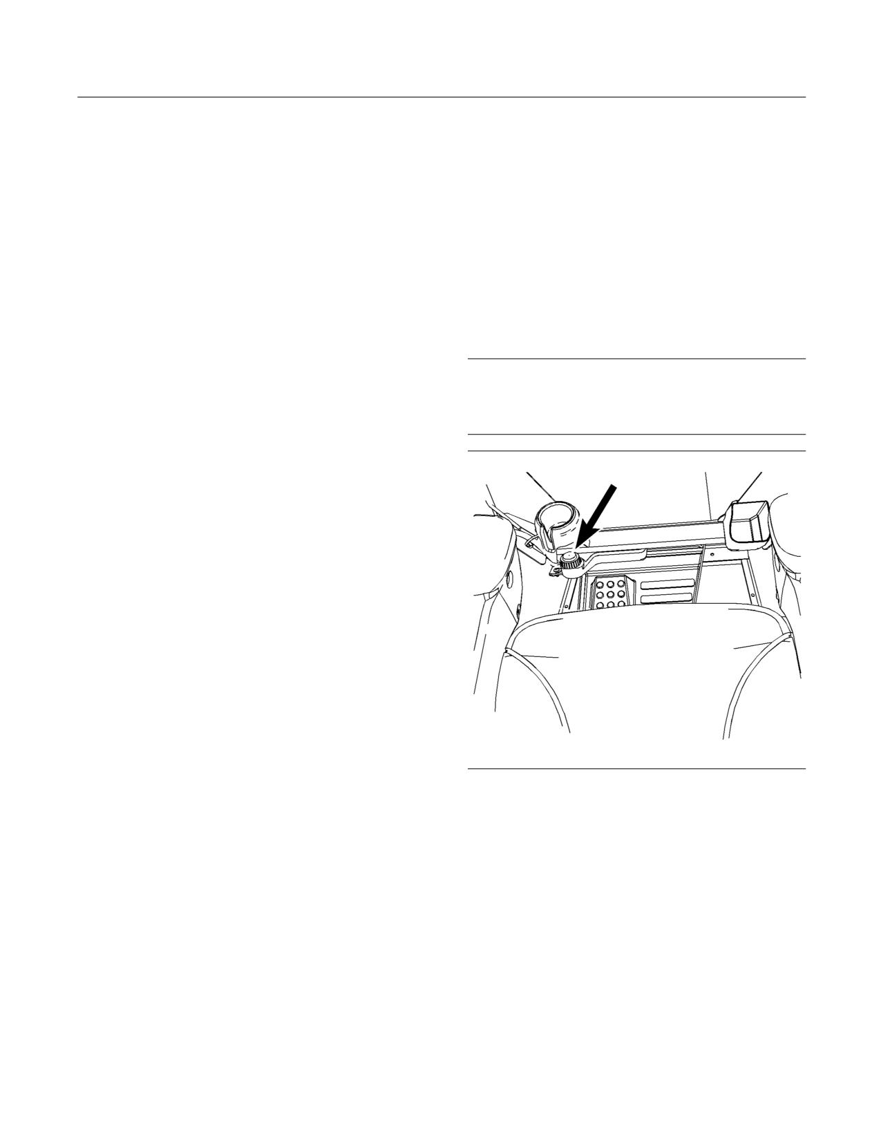
172
SEBU8407-06
Maintenance Section
Track Roller and Idler - Inspect/Replace
8. Lift the track over the sprocket with a suitable
Note: The idlers and the rollers contain oil. The idlers
lifting device. The inner guides need to clear the
and the rollers are sealed for life. Periodically, inspect
sprocket teeth.
the idlers and the rollers for leaks or for excessive
end play. Contact your Caterpillar dealer if either
9. Lift the track over the rear idler. The inner track
leaks or excessive end play is found.
guides need to clear the rear idler.
i02418610
Installing the Track
Window Washer Reservoir -
Note: The approximate weight of the track is 247 kg
Fill
(545 lb).
(If Equipped)
1. Use a suitable lifting device. Slide the track onto
the rear idler so that the inner track guides straddle
SMCS Code: 7306-544-KE
the rear idler. If your machine is equipped with an
idler with dual flanges, the inner track guides must
NOTICE
seat between the flanges.
When operating in freezing temperatures, use
Caterpillar nonfreezing window washer solvent or
2. Pull the track forward in order to ensure that the
equivalent. System damage can result from freezing.
track guides are fully seated on the rear idler.
3. Lift the track over the final drive sprocket so that
the inner track guides straddle the sprocket teeth.
The sprocket teeth should seat in the openings in
the middle of the track.
4. Pull all of the slack forward. This will provide the
maximum amount of slack to aid with installation
across the front idlers.
Note: It is helpful to support the bottom of the track
in order to maximize the slack. This will help with
installation.
5. Position the track so that the inner track guides
seat between the flanges on the front idler.
6. Tension the track. Refer to Operation and
Maintenance Manual, “Track - Inspect/Adjust” for
the procedure.
g01209248
Illustration 188
i03880910
Track Roller and Idler -
The reservoir for the window washer solvent is
located inside the cab by the left footrest.
Inspect/Replace
Fill the reservoir with window washer solvent.
SMCS Code: 4159-040; 4159-510; 4180-040;
Window washer solvent with isopropyl alcohol is
4180-510
recommended.
Inspect
Clean the undercarriage before inspecting the idlers
and the rollers.
Inspect the idlers and the rollers for damage and
wear.
The idlers and the rollers should be replaced when
the damage to the wheels adversely affects machine
performance.
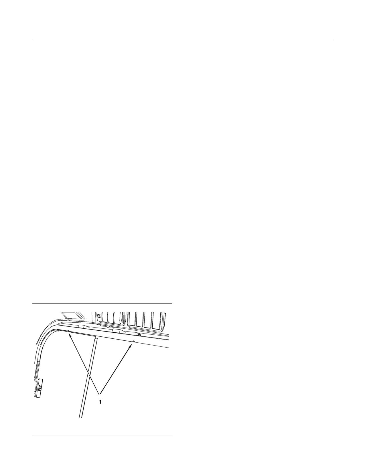
SEBU8407-06
173
Maintenance Section
Window Wiper - Inspect/Replace
i02810705
1. Release the latch. Slide the front window rearward
between the circular marks (1) in the top of the
Window Wiper -
window frame. Push the window upward in the
track. Pull outward on the bottom of the window in
Inspect/Replace
order to remove the window.
(If Equipped)
2. Release the latch. Slide the rear window forward
SMCS Code: 7305-040; 7305-510
between the circular marks (1) in the top of the
window frame. Push the window upward in the
Inspect the condition of the front window wiper blade.
track. Pull outward on the bottom of the window in
Replace the window wiper blade if the window wiper
order to remove the window.
blade is worn or damaged. If the window wiper blade
streaks the window, replace the window wiper blade.
3. Pull straight up on the bottom window in order to
remove the window from the track. Pull inward in
order to remove the window.
i02418633
Windows - Clean
4. Reverse the process in order to install the
windows. Install the lower window first. Then
SMCS Code: 7310-070
install the rear window in the outer track. Install
the front window in the inner track next.
Rear Window and Glass Front Door
Polycarbonate Front Door and
Use commercially available window cleaning
Polycarbonate Top Window
solutions in order to clean the windows.
Note: Do not wipe the window dry. Do not use
Apply the cleaning solution liberally. Wipe the surface.
paper towels. This may scratch the finish of the
polycarbonate windows over time.
Dry the surface in order to prevent spots.
For cleaning your polycarbonate top window or
Side Windows
polycarbonate front door, use a soft cloth, a sponge,
or a chamois. Use any of the following cleaners:
Use commercially available window cleaning
solutions in order to clean the windows.
• soap and water
The side windows of the cab can be removed for
• isopropyl alcohol
cleaning. Refer to the following procedure in order to
remove the side windows.
• kerosene
• denatured alcohol
• commercially available window cleaning solutions
Apply the cleaning solution liberally. Wipe the surface.
g01209231
Illustration 189
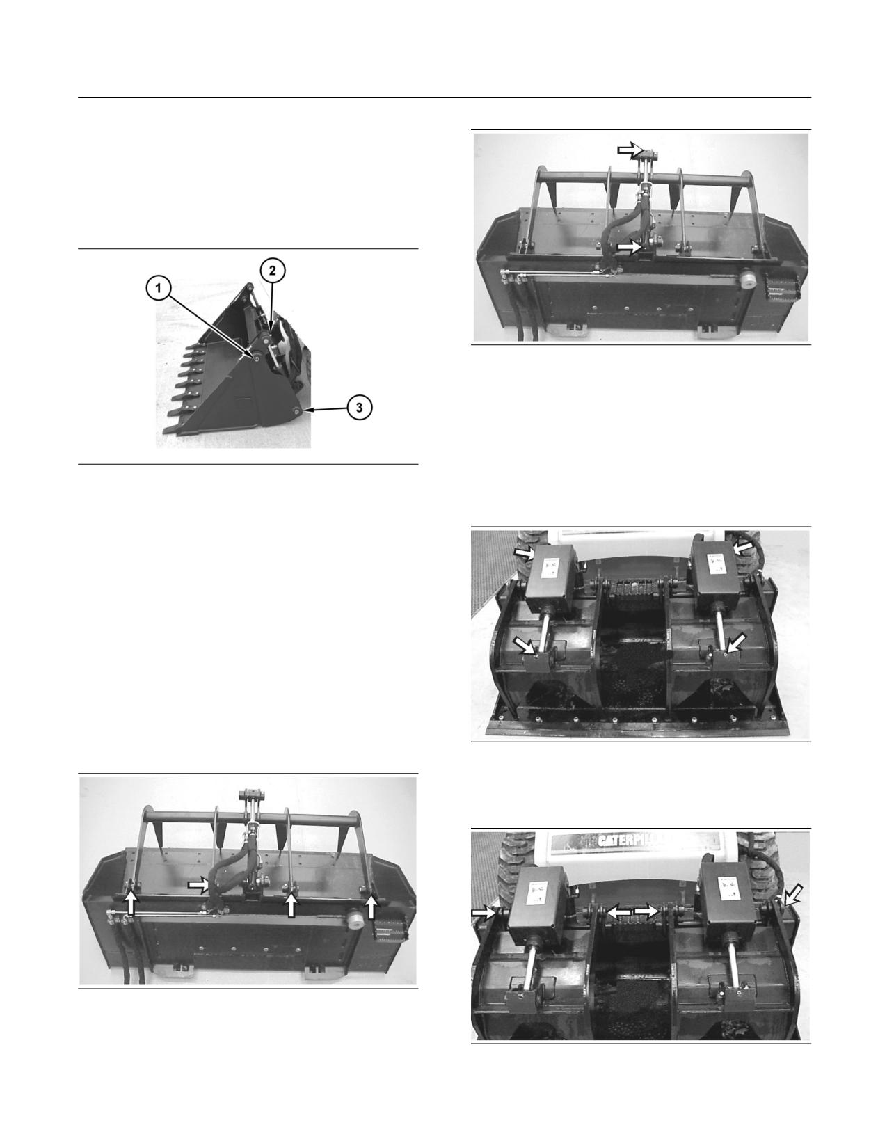
174
SEBU8407-06
Maintenance Section
Work Tool - Lubricate
i02729220
Work Tool - Lubricate
SMCS Code: 6700-086
Multipurpose Bucket
g00647988
Illustration 192
Apply lubricant to the two fittings for the grapple
cylinder.
There are six grease fittings.
g01280216
Illustration 190
Industrial Grapple Bucket and
Industrial Grapple Fork
Apply lubricant to the grease fitting (1) for the pivot
pin of the apron.
Apply lubricant to the grease fitting (2) for the rod end
of the multipurpose bucket cylinder.
Apply lubricant to the grease fitting (3) for the head
end of the multipurpose bucket cylinder.
Repeat for the other side of the bucket.
There are six grease fittings.
Utility Grapple Bucket and Utility
Grapple Fork
g00645995
Illustration 193
Apply lubricant to the four grease fittings for the fork
cylinders.
g00647980
Illustration 191
Apply lubricant to the four grease fittings for the
grapples.
g00646004
Illustration 194
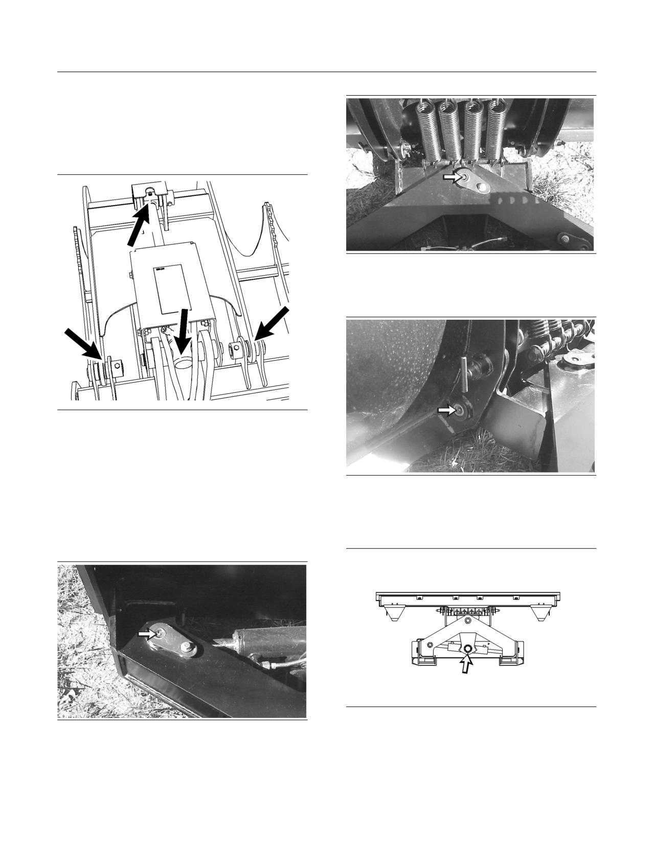
SEBU8407-06
175
Maintenance Section
Work Tool - Lubricate
Apply lubricant to the four grease fittings for the two
forks.
There are eight grease fittings.
Grapple Rake
g00648037
Illustration 197
Apply lubricant to the grease fitting on the horizontal
pivot point of the blade.
g01368386
Illustration 195
Apply lubricant to the four grease fittings for the
grapple cylinders.
Apply lubricant to the four grease fittings for the two
g00648038
Illustration 198
grapples.
Apply lubricant to the grease fitting on the vertical
There are eight grease fittings.
pivot point of the blade. Repeat for opposite side of
the blade.
Angle Blade
g00677570
Illustration 199
g00648033
Illustration 196
This is a bottom view of the angle blade.
Apply lubricant to the grease fitting on the rod end of
Apply lubricant to the grease fitting on the pivot point
the angle cylinder.
of the cylinder.
There are five grease fittings.
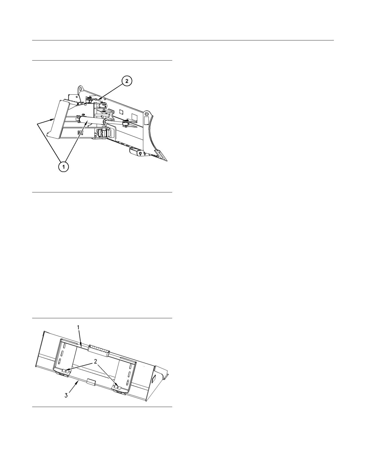
176
SEBU8407-06
Maintenance Section
Work Tool Mounting Bracket - Inspect
Dozer Blade
Inspect upper angled plate (1) and ensure that the
plate is not bent or otherwise damaged. Inspect holes
(2) for wear and for damage. Inspect lower angled
plate (3) and ensure that the plate is not bent or
otherwise damaged. If any wear is suspected or any
damage is suspected, consult your Caterpillar dealer
before you use the work tool.
g01073259
Illustration 200
Apply lubricant to the grease fitting on both ends of
the right hand angle cylinder (1). Repeat for opposite
side of the blade.
Apply lubricant to the grease fitting on the pivot points
on each end of the tilt cylinder (2).
There are six grease fittings.
i01809997
Work Tool Mounting Bracket -
Inspect
SMCS Code: 6700-040-BK
g00925058
Illustration 201
SEBU8407-06
177
Reference Information Section
Reference Materials
Special Publication, PEHJ0009, “Product Data Sheet
Reference Information
for Caterpillar Hydraulic Oil (HYDO) (SAE 10W)”
Section
Special Publication, PEHP6047, “Product Data Sheet
for Caterpillar Biodegradable Hydraulic Oil (HEES)”
Reference Materials
Miscellaneous Publications
i02836324
Special Publication, PECP9067, “One Safe Source”
Reference Material
Special Publication, PEDP9131, “Fluid Contamination
- The Silent Thief”
SMCS Code: 1000; 7000
Special Publication, PEWJ0074, “Cat Filter & Fluid
Application Guide”
Cooling System
Special Publication, REHS1199, “Installation
Special Publication, PMEP5027, “Label - ELC
Procedure for the Multi Terrain Loader Track Guide”
Radiator Label”
Special Publication, SEBD0400, “Dictionary of
Special Publication, PEHJ0067, “Product Data Sheet
Pictographic Symbols”
for Caterpillar ELC”
Special Publication, SEBD0717, “Diesel Fuels and
Special Publication, PEHP9554, “Product Data
Your Engine”
Sheet for Caterpillar DEAC (Diesel Engine
Antifreeze/Coolant)”
Special Publication, SEBF1015, “Improving
Component Durability - Final Drives and Differentials”
Special Publication, SEBD0518, “Know Your Cooling
System”
Undercarriage Reconditioning Bulletin, SEBF8501,
“Undercarriage Reconditioning Guide”
Special Publication, SEBD0970, “Coolant and Your
Engine”
Special Publication, SEBU6250, “Caterpillar Machine
Fluid Recommendations”
Grease
Special Publication, SEBU5898, “Cold Weather
Data Sheet, NEHP6010, “Cat Ultra 5Moly Grease
Recommendations”
(NLGI grade 1 and grade 2)”
Special Publication, SENR5664, “Air Conditioning
Data Sheet, NEHP6011, “Cat Arctic Platinum Grease
and Heater R-134a for All Caterpillar Machines”
(NLGI grade 0)”
Special Publication, SENR9620, “Improving Fuel
Data Sheet, NEHP6012, “Cat Desert Gold Grease
System Durability”
(NLGI grade 2)”
Special Publication, SMBU6981, “Emissions Control
Data Sheet, NEHP6015, “Cat High Speed Ball
Warranty Information”
Bearing Grease (NLGI grade 2)”
Oil
Special Publication, PEGJ0035, “Grease Selection
Guide”
Special Publication, PEHP3050, “Product Data Sheet
for Caterpillar Multipurpose Tractor Oil (MTO)”
Data Sheet, PEHJ0088, “Cat Multipurpose Grease
(NLGI grade 2)”
Special Publication, PEHP6001, “How to Take a
Good Oil Sample”
Data Sheet, PEHP0002, “Cat Advanced 3Moly
Grease (NLGI grade 2)”
Special Publication, PEHJ0007, “Product Data Sheet
for Caterpillar Arctic TDTO (SAE 0W-20) (synthetic
Hydraulic Oil
blend)”
Special Publication, PEGP6028, “Caterpillar
Special Publication, PEHJ0008, “Product Data Sheet
Hydraulic Systems Management Guide”
for Caterpillar Arctic DEO (SAE 0W-30)”
178
SEBU8407-06
Reference Information Section
Reference Materials
Special Publication, PEHJ0030, “Product Data Sheet
ROPS/FOPS Structure
for Caterpillar Synthetic Gear Oil (SAE 75W-140)”
Special Publication, SEBD1587, “What ROPS/FOPS
Special Publication, PEHJ0059, “Product Data Sheet
Certification Means”
for Caterpillar DEO (SAE 10W-30)”
Special Publication, SEHS6929, “Inspection,
Special Publication, PEHP7506, “Product Data Sheet
Maintenance and Repair of ROPS and Attachment
for Caterpillar TDTO (SAE 10W, SAE 30, SAE 50)”
Installation Guidelines”
Special Publication, PEHP7508, “Product Data Sheet
Safety Manuals
for Caterpillar Gear Oil (GO) (SAE 80W-90 and SAE
85W-140)”
Safety DVD, TEVD6193, “C-Series Skid Steer Loader
and Multi Terrain Loader Safety & Operating Tips”
Special Publication, PEHP7062, “Product Data Sheet
for Caterpillar DEO Synthetic (SAE 5W-40)”
S·O·S Information
Special Publication, PEHP9530, “Product Data Sheet
for Caterpillar FDAO (SAE 60)”
Special Publication, PEDP7036, “S·O·S Services”
Special Publication, PEHP9570, “Product Data Sheet
Special Publication, PEHP7052, “Making the Most
for Caterpillar FDAO Synthetic (Multigrade)”
of S·O·S Services”
Special Publication, PELJ0179, “Caterpillar Engine
Special Publication, PEHP7057, “S·O·S Coolant
Crankcase Fluid-1 Specifications (Cat ECF-1)”
Analysis”
Special Publication, PEHP8035, “Product Data Sheet
Special Publication, PEHP7076, “Understanding
for TDTO Transmission Multi-Season (TMS)”
S·O·S Services Tests”
Special Publication, SEBD0640, “Oil and Your
Specifications Manuals
Engine”
Specifications Manual, SENR3130, “Torque
Operation and Maintenance
Specifications”
Manuals
Tools
Operation and Maintenance Manual, SEBU5898,
“Cold Weather Recommendations”
Special Publication, NENG2500, “Caterpillar Dealer
Service Tool Catalog”
Operation and Maintenance Manual, SEBU8257,
“The European Union Physical Agents (Vibration)
Additional Reference Material
Directive 2002/44/EC”
SAE J183, “Classification” This can normally be
Operation and Maintenance Manual, SMBU6981,
found in the SAE handbook.
“Emissions Control Warranty Information”
SAE J313, “Diesel Fuels” This can be found in the
Parts Manuals
SAE handbook. Also, this publication can be obtained
from your local technological society, from your local
Parts Manual, SEBP5067 279C
library, or from your local college.
Parts Manual - Compact Disc, SERP5067 279C
SAE J754, “Nomenclature” This can normally be
found in the SAE handbook.
Parts Manual, SEBP5068 289C
Engine Manufacturers Association, “ Engine Fluids
Parts Manual - Compact Disc, SERP5068 289C
Data Book”
Parts Manual, SEBP5069 299C
Engine Manufacturers Association
Two North LaSalle Street, Suite 2200
Parts Manual - Compact Disc, SERP5069 299C
Chicago, Illinois USA 60602
E-mail: ema@enginemanufacturers.org
(312) 827-8700
Facsimile: (312) 827-8737
SEBU8407-06
179
Reference Information Section
Reference Materials
i03708448
Caterpillar Approved Work
Tools
SMCS Code: 6700
Only use Caterpillar approved work tools on this
machine.
Note: Do not use a Caterpillar work tool on a machine
that is not approved by Caterpillar.
Note: A Debris Barrier Kit is required for use in
applications which create airborne debris. Consult
your Caterpillar dealer for information about this kit.
Use of the following equipment may create airborne
debris:
• mulching head
• brush cutter
• hammers
• recycling of paper products
• certain agricultural applications
Caterpillar approves the following work tools for use
on this machine:
Table 31
Caterpillar Approved Work Tools for Multi Terrain Loaders
Machine
279C
289C
299C
General Purpose Buckets
60
N
N
N
66
N
N
N
72
A
A
A
78
O
O
O
High Capacity Buckets
84
O
O
O
Multipurpose Buckets
60
N
N
N
66
N
N
N
72
A
A
A
78
O
O
O
84
O
O
O
Dirt Buckets
54
N
N
N
(continued)
180
SEBU8407-06
Reference Information Section
Reference Materials
(Table 31, contd)
Caterpillar Approved Work Tools for Multi Terrain Loaders
Machine
279C
289C
299C
60
N
N
N
66
N
N
N
72
A
A
A
78
O
O
O
Light Material Buckets
72
A
A
A
78
O
O
O
84
O
O
O
96
O
O
O
Utility Buckets
60
N
N
N
66
N
N
N
72
A
A
A
Augers
A14B
O
O
O
A19B
O
O
O
A26B
#
#
#
Backhoes
BH150
!
!
!
BH160
O
O
O
Angle Blades
72
N
N
N
84
O
O
O
Dozer Blades
79
A
A
A
92
O
O
O
Brooms
BA18
O
O
O
BP15B
A
A
A
BP18B
O
O
O
BU115
A
A
A
BU118
O
O
O
Brush cutters
BR160
O
O
O
BR166
O
O
O
BR172
O
O
O
BR272
!
!
!
(continued)
SEBU8407-06
181
Reference Information Section
Reference Materials
(Table 31, contd)
Caterpillar Approved Work Tools for Multi Terrain Loaders
Machine
279C
289C
299C
BR378
#
#
#
Cold Planers
PC203
O
O
O
PC204
O
O
O
PC205
#
#
#
PC206
#
#
#
PC210
#
#
#
Carriage and Fork Tines
O
O
O
Utility Forks
66
A
A
A
72
O
O
O
Industrial Grapple Buckets
60
N
N
N
66
N
N
N
72
A
A
A
78
O
O
O
Industrial Grapple Forks
66
A
A
A
72
O
O
O
Utility Grapple Buckets
60
N
N
N
66
N
N
N
72
A
A
A
Utility Grapple Forks
66
A
A
A
72
O
O
O
Grapple Rake
72
O
O
O
84
O
O
O
Landscape Rakes
LR15B
N
N
N
LR18B
O
O
O
Landscape Tillers
LT13B
N
N
N
LT18B
O
O
O
Material Handling Arm
(continued)
182
SEBU8407-06
Reference Information Section
Reference Materials
(Table 31, contd)
Caterpillar Approved Work Tools for Multi Terrain Loaders
Machine
279C
289C
299C
O
O
O
Mulcher
HM312
#
#
#
Power Box Rakes
PR172 MAN
A
A
A
PR172 HYD
A
A
A
PR184 MAN
O
O
O
PR184 HYD
O
O
O
PR190 MAN
O
O
O
PR190 HYD
O
O
O
Sheer
S305
O
O
O
Hammers
H55Ds
O
O
O
H63/H63s
O
O
O
Snowblowers
SR17
N
N
N
SR18
A
A
A
SR21
O
O
O
SR318
X
X
X
SR321
#
#
#
Stump Grinders
SG16B
O
O
O
SG18B
#
#
#
Trenchers
T6B
O
O
O
T9B
O
O
O
T15B
#
#
#
Vibratory Compactors
CV16B
O
O
O
CV18B
O
O
O
Wheel Saws
SW45 (3 inches)
#
#
#
SW45 (6 inches)
#
#
#
SW45 (8 inches)
#
#
#
SW60 (6 inches)
#
#
#
SW60 (8 inches)
#
#
#
SEBU8407-06
183
Reference Information Section
Reference Materials
O - The machine performance is optimum with this
Do not use the work tool improperly.
work tool.
Remove the work tool from the machine before
A - The machine performance is acceptable with
you lift the host machine. Refer to Operation and
this work tool.
Maintenance Manual, “Lifting and Tying Down the
Machine” for details.
HF - The machine is equipped with high flow
hydraulics.
INTENDED USE STATEMENT for
NR - This work tool is not recommended for use on
the Grapple Bucket
this machine.
This Work Tool has the intended functions of digging,
# - The machine performance is optimum with the
loading, lifting, carrying, and moving material such as
available HF/XPS option.
earth, crushed rock, gravel, or debris.
X - The machine performance is acceptable with the
Do not use the work tool improperly.
available HF/XPS option.
Remove the work tool from the machine before
! - This work tool is not approved for use on this
you lift the host machine. Refer to Operation and
machine. Do not use this work tool on this machine.
Maintenance Manual, “Lifting and Tying Down the
Machine” for details.
* - This work tool has a lift restriction on this
machine. Do not raise the lower pivot pin higher than
INTENDED USE STATEMENT for
1 m (3 ft) above the ground.
the Grapple Rake
Many of the work tools in the table have an Operation
and Maintenance Manual. Please refer to the
This Work Tool has the intended functions of raking,
Operation and Maintenance Manual that is provided
loading, carrying, and moving bulky material. The
with the work tool for the proper use of the work tool.
material may be encountered in the following
applications:
Contact your Caterpillar dealer concerning specific
work tools that are approved by Caterpillar for this
• Landscape cleanup
machine. This list was complete at the time of
publication. There may be additional work tools that
• Storm debris cleanup
have been approved since that time. Consult your
Caterpillar dealer for an updated list of approved
• Demolition
work tools.
• Industrial
INTENDED USE STATEMENT for
• Construction
the Material Handling Arm
Do not use the work tool improperly.
This Work Tool has the intended functions of lifting
and transporting suspended loads. Always select
• Do not pry with one rake tine. Use multiple rake
sufficiently sized lifting accessories. Always inspect
tines in order to loosen material.
the lifting accessories before use.
•
Remove the work tool from the machine before
Do not use the work tool improperly.
you lift the host machine. Refer to Operation and
Maintenance Manual, “Lifting and Tying Down the
Remove the work tool from the machine before
Machine” for details.
you lift the host machine. Refer to Operation and
Maintenance Manual, “Lifting and Tying Down the
• Do not place the weight of the host machine on the
Machine” for details.
grapples in the open position.
INTENDED USE STATEMENT for
INTENDED USE STATEMENT for
the Multipurpose Bucket
the Grapple Forks
This Work Tool has the intended functions of dozing,
This Work Tool has the intended functions of loading,
digging, loading, lifting, carrying, and moving material
carrying, and moving bulky materials.
such as earth, crushed rock, or gravel.
Do not use the work tool improperly.
184
SEBU8407-06
Reference Information Section
Reference Materials
Remove the work tool from the machine before
you lift the host machine. Refer to Operation and
Maintenance Manual, “Lifting and Tying Down the
Machine” for details.
i03989612
Decommissioning and
Disposal
SMCS Code: 1000; 7000
When the product is removed from service, local
regulations for the product decommissioning will
vary. Disposal of the product will vary with local
regulations. Consult the nearest Cat dealer for
additional information.
SEBU8407-06
185
Index Section
Index
A
Caterpillar Approved Work Tools
179
INTENDED USE STATEMENT for the Grapple
Access Doors and Covers
113
Bucket
183
Engine Access Door
113
INTENDED USE STATEMENT for the Grapple
Additional Messages
23
Forks
183
Product Link (If Equipped)
23
INTENDED USE STATEMENT for the Grapple
Aftercooler Core - Inspect/Clean
129
Rake
183
Clean
129
INTENDED USE STATEMENT for the Material
Inspect
129
Handling Arm
183
Aftercooler Intake Screen - Clean
130
INTENDED USE STATEMENT for the Multipurpose
Air Cleaner Dust Valve - Clean/Inspect
130
Bucket
183
Air Conditioner Condenser - Clean (If Equipped).. 131
Cooling System Coolant (ELC) - Change
138
246C, 256C, 262C, 277C, 287C, 279C, and
Cooling System Coolant Extender (ELC) - Add... 140
289C
131
Cooling System Coolant Sample (Level 1) -
272C, 297C, and 299C
131
Obtain
141
Alert Indicators
80
Cooling System Coolant Sample (Level 2) -
Machine Security System (If Equipped)
83
Obtain
142
Alternate Exit
60
Cooling System Level - Check
143
Primary Exit
60
Cooling System Water Temperature Regulator -
Secondary Exit
60
Replace
143
Angle Blade Operation
96
Crushing Prevention and Cutting Prevention
26
Height Adjustment
96
Tilt Lock
96
Axle Bearings - Lubricate
132
D
Daily Inspection
59
B
Declaration of Conformity
53-58
Decommissioning and Disposal
184
Backup Alarm - Test
132
Battery or Battery Cable - Inspect/Replace
132
Recycle the Battery
133
E
Before Operation
32, 59
Before Starting Engine
31
Electrical Storm Injury Prevention
31
Belts - Inspect/Adjust/Replace
133
Emissions Certification Film
52
Air Conditioner (if equipped)
134
Certification Label for Emissions
52
Belts
133
Engine Air Filter Primary Element - Clean/
Finish
134
Replace
144
Blade Frame - Adjust
135
Clean
145
Height Adjustment
135
Replace
145
Trunnion Joint
136
Engine Air Filter Secondary Element - Replace .. 146
Bucket Cutting Edges - Inspect/Replace
136
Engine Compartment - Inspect/Clean
147
Bucket Tips - Inspect/Replace
136
Engine Oil and Filter - Change
148
Burn Prevention
26
Engine Oil Level - Check
148
Batteries
27
Engine Starting
32, 84
Coolant
26
Engine Starting (Alternate Methods)
111
Oils
27
Engine Starting with Jump Start Cables
111
Engine Valve Lash - Check
150
Equipment Lowering Control Valve - Check
150
C
Equipment Lowering with Engine Stopped
34, 100
Alternate Lowering the Equipment
101
Cab Air Filter - Clean/Replace (If Equipped)
137
Lowering the Equipment with the Accumulator
Fresh Air Filter
137
Charged
101
Recirculation Filter
137
Cab Interior - Clean
137
Cab Tilting
114
F
Tilting the Cab Downward
115
Tilting the Cab Upward
114
Final Drive Oil - Change
151
Capacities (Refill)
122
Final Drive Oil Level - Check
151
186
SEBU8407-06
Index Section
Fire Extinguisher Location
31
I
Fire Prevention and Explosion Prevention
27
Battery and Battery Cables
28
Identification Information
51
Ether
30
Important Safety Information
2
Fire Extinguisher
30
General
27
Lines, Tubes, and Hoses
29
L
Wiring
29
Fire Safety
30
Lift Arm and Cylinder Linkage - Lubricate
163
Foreword
5
Lifting and Tying Down the Machine
104
California Proposition 65 Warning
4
Lifting the Grapple Rake
106
Caterpillar Product Identification Number
5
Lifting the Machine
104
Certified Engine Maintenance
4
Tying Down the Machine
106
Literature Information
4
Loader Lift Arm Brace Operation
115
Machine Capacity
5
Disengage the Lift Arm Brace
116
Maintenance
4
Engage the Lift Arm Brace
116
Operation
4
Lower Machine Frame - Clean
163
Safety
4
Lubricant Viscosities
118
Fuel Injection Timing - Check
152
Biodiesel
122
Fuel System Primary Filter (Water Separator) -
Coolant Information
122
Drain
152
Diesel Fuel Recommendations
121
Fuel System Primary Filter (Water Separator)
Drive Train Components
120
Element - Replace
153
Engine Oil
118
Fuel System Priming Pump - Operate
154
Fuel Additives
122
Fuel Tank Cap - Clean
154
General Information for Lubricants
118
Fuel Tank Water and Sediment - Drain
154
Hydraulic Systems
119
Fuses - Replace
155
Selecting the Viscosity
118
Fuse panel behind cab
157
Special Lubricants
121
Fuses
155
Lubricant Viscosities and Refill Capacities
118
Main Fuse
157
M
G
Machine Operation
60
General Hazard Information
23
Machine Retrieval
109
Containing Fluid Spillage
25
Machine Storage Procedure
102
Dispose of Waste Properly
26
Maintenance Access
113
Fluid Penetration
25
Maintenance Interval Schedule
127
Inhalation
25
Maintenance Section
113
Pressurized Air and Water
24
Maintenance Support
124
Trapped Pressure
24
Material Handling Arm Operation
92
General Information
39
One Person Operation
93
Guards (Operator Protection)
37
Two Person Operation
92
Other Guards (If Equipped)
37
Mounting and Dismounting
59
Rollover Protective Structure (ROPS), Falling
Object Protective Structure (FOPS) or Tip Over
Protection Structure (TOPS)
37
O
Oil Filter - Inspect
164
H
Inspect a Used Filter for Debris
164
Operation
32, 85
Hydraulic System Oil - Change
158
Operation Information
85
Procedure for Changing the Hydraulic Oil
159
Counterrotate turn
86
Selection of the Oil Change Interval
158
General Information
85
Hydraulic System Oil Filter - Replace
160
Operating on a Slope
85
Hydraulic System Oil Level - Check
161
Operating on a Transition
86
Hydraulic System Oil Sample - Obtain
162
Operation Section
59
Hydraulic Tank Breather - Replace
162
SEBU8407-06
187
Index Section
Operator Controls
63
Rated Load
39
12 volt plug (14)
67
Bucket Rated Load
39
Air Conditioner Control (27)
69
Rated Load with a Material Handling Arm
46
Alert Indicator Panel (16)
67
Rated Loads for Forks
43
Automatic Level Control (7)
66
Reference Information Section
177
Auxiliary Electrical Control (E)
80
Reference Material
177
Auxiliary Electrical Control “AUX 8”
66
Additional Reference Material
178
Auxiliary Hydraulic Controls
79
Cooling System
177
Auxiliary Hydraulic Pressure Release (1)
64
Grease
177
Beacon Switch (20)
68
Hydraulic Oil
177
Coolant Temperature (17)
68
Miscellaneous Publications
177
Creeper Control (24)
69
Oil
177
Digital Display Window
70
Operation and Maintenance Manuals
178
Digital Display Window (19)
68
Parts Manuals
178
Engine Start Switch (13)
67
ROPS/FOPS Structure
178
Fan Speed Control (26)
69
S·O·S Information
178
Front Work Lights (4)
65
Safety Manuals
178
Fuel Level Gauge (9)
66
Specifications Manuals
178
Hazard Flashers (21)
68
Tools
178
Hydraulic Lockout and Interlock Override (2)
65
Reference Materials
177
Hydraulic Oil Temperature (18)
68
Refrigerant Dryer - Replace (If Equipped)
166
Joystick Control Pattern (11)
67
Roading the Machine
104
Joystick Controls
74
Rollover Protective Structure (ROPS) and Falling
Left Side Controls
64
Object Protective Structure (FOPS) - Inspect
167
Multifunction Switch for the Left Hand Trigger
(5)
65
Other Features in the Cab
72
S
Parking Brake Control (12)
67
Rear Work Lights (3)
65
S·O·S Information
122
Ride Control (25)
69
Safety Messages
6
Right Side Controls
68
Safety Messages (Work Tools)
15
Roading Lights (22)
69
Safety Section
6
Selectable Control Pattern and Dedicated Control
Seat Belt
61
Pattern
76
Extension of the Seat Belt
63
Service Hour Meter (10)
66
Seat Belt Adjustment for Non-Retractable Seat
Temperature Control (28)
69
Belts
61
Turn Signals (23)
69
Seat Belt Adjustment for Retractable Seat
Window Wiper and Window Washer (15)
67
Belts
62
Work Tool Coupler Control (8)
66
Seat Belt - Inspect
167
Seat Belt - Replace
168
Service Interval Chart
124
P
279C Service Interval Chart
124
289C and 299C Service Interval Chart
125
Pallet Forks Operation
95
Service Intervals
125
Parking
33, 99
Shipping the Machine
103
Plate Locations and Film Locations
51
Loading the Machine
103
Product Information Section
39
Unloading the Machine
104
Slope Operation
33
Sound Information and Vibration Information
34
Q
“European Physical Agents Directive (Vibration)
2002/44/EC”
35
Quick Coupler - Clean/Inspect
165
Sound Level Information
34
Sound Level Information for Machines in European
Union Countries and in Countries that Adopt the
R
“EU Directives”
35
Sources
37
Radiator Core - Clean
165
Specifications
48
Radiator Tilting
116
Application/Configuration Restrictions
48
Tilting the Radiator Guard
117
Diesel Fuel Requirements
48
Intended Use
48
Machine Data
49
188
SEBU8407-06
Index Section
Sprocket - Inspect
168
Work Tool Operation
96
Sprocket Inspection for 279C, 289C, and
Complex Hydromechanical Work Tools
98
299C
168
Simple Hydromechanical Work Tools
97
Stopping the Engine
99
Work Tools
33
Stopping the Engine if an Electrical Malfunction
Occurs
99
Inside Cab
99
Outside Cab
100
T
Table of Contents
3
Tilt Cylinder Bearings and Bucket Linkage Bearings -
Lubricate
169
Towing Information
109
Track - Inspect/Adjust
169
Detension the track
171
Inspect
170
Track Adjustment
170
Track - Remove/Replace
171
Installing the Track
172
Removing the Track
171
Track Roller and Idler - Inspect/Replace
172
Inspect
172
Transportation Information
103
V
Visibility Information
31
W
Welding on Machines and Engines with Electronic
Controls
126
Window Washer Reservoir - Fill (If Equipped)
172
Window Wiper - Inspect/Replace (If Equipped)... 173
Windows - Clean
173
Polycarbonate Front Door and Polycarbonate Top
Window
173
Rear Window and Glass Front Door
173
Side Windows
173
Work Tool - Lubricate
174
Angle Blade
175
Dozer Blade
176
Grapple Rake
175
Industrial Grapple Bucket and Industrial Grapple
Fork
174
Multipurpose Bucket
174
Utility Grapple Bucket and Utility Grapple
Fork
174
Work Tool Coupler Operation
87
Attaching the Work Tool
87
Releasing the Auxiliary Hydraulic System
Pressure
91
Removing the Work Tool
90
Work Tool Mounting Bracket - Inspect
176
Product and Dealer Information
Note: For product identification plate locations, see the section “Product Identification Information” in the Operation
and Maintenance Manual.
Delivery Date:
Product Information
Model:
Product Identification Number:
Engine Serial Number:
Transmission Serial Number:
Generator Serial Number:
Attachment Serial Numbers:
Attachment Information:
Customer Equipment Number:
Dealer Equipment Number:
Dealer Information
Name:
Branch:
Address:
Dealer Contact
Phone Number
Hours
Sales:
Parts:
Service: