Caterpillar. 279C, 289C and 299C Compact Track Loaders. Operation and Maintenance Manual - page 1
SEBU8407-06
February 2012
Operation and
Maintenance
Manual
279C, 289C and 299C Compact Track
Loaders
MBT1-Up (279C)
JMP1-Up (289C)
JSP1-Up (299C)
SAFETY.CAT.COM
i03991620
Important Safety Information
Most accidents that involve product operation, maintenance and repair are caused by failure to observe
basic safety rules or precautions. An accident can often be avoided by recognizing potentially hazardous
situations before an accident occurs. A person must be alert to potential hazards. This person should also
have the necessary training, skills and tools to perform these functions properly.
Improper operation, lubrication, maintenance or repair of this product can be dangerous and
could result in injury or death.
Do not operate or perform any lubrication, maintenance or repair on this product, until you have
read and understood the operation, lubrication, maintenance and repair information.
Safety precautions and warnings are provided in this manual and on the product. If these hazard warnings
are not heeded, bodily injury or death could occur to you or to other persons.
The hazards are identified by the “Safety Alert Symbol” and followed by a “Signal Word” such as
“DANGER”, “WARNING” or “CAUTION”. The Safety Alert “WARNING” label is shown below.
The meaning of this safety alert symbol is as follows:
Attention! Become Alert! Your Safety is Involved.
The message that appears under the warning explains the hazard and can be either written or pictorially
presented.
A non-exhaustive list of operations that may cause product damage are identified by “NOTICE” labels
on the product and in this publication.
Caterpillar cannot anticipate every possible circumstance that might involve a potential hazard.
The warnings in this publication and on the product are, therefore, not all inclusive. You must
not use this product in any manner different from that considered by this manual without first
satisfying yourself that you have considered all safety rules and precautions applicable to the
operation of the product in the location of use, including site-specific rules and precautions
applicable to the worksite. If a tool, procedure, work method or operating technique that is not
specifically recommended by Caterpillar is used, you must satisfy yourself that it is safe for you
and for others. You should also ensure that the product will not be damaged or become unsafe by
the operation, lubrication, maintenance or repair procedures that you intend to use.
The information, specifications, and illustrations in this publication are on the basis of information that
was available at the time that the publication was written. The specifications, torques, pressures,
measurements, adjustments, illustrations, and other items can change at any time. These changes can
affect the service that is given to the product. Obtain the complete and most current information before you
start any job. Cat dealers have the most current information available.
When replacement parts are required for this
product Caterpillar recommends using Cat re-
placement parts or parts with equivalent speci-
fications including, but not limited to, physical
dimensions, type, strength and material.
Failure to heed this warning can lead to prema-
ture failures, product damage, personal injury or
death.
In the United States, the maintenance, replacement, or repair of the emission control devices and
systems may be performed by any repair establishment or individual of the owner's choosing.
SEBU8407-06
3
Table of Contents
Engine Starting
84
Table of Contents
Operation
85
Foreword
4
Parking
99
Safety Section
Transportation Information
103
Safety Messages
6
Towing Information
109
Safety Messages (Work Tools)
15
Engine Starting (Alternate Methods)
111
Additional Messages
23
Maintenance Section
General Hazard Information
23
Maintenance Access
113
Crushing Prevention and Cutting Prevention
26
Lubricant Viscosities and Refill Capacities
118
Burn Prevention
26
Maintenance Support
124
Fire Prevention and Explosion Prevention
27
Maintenance Interval Schedule
127
Fire Safety
30
Reference Information Section
Fire Extinguisher Location
31
Reference Materials
177
Electrical Storm Injury Prevention
31
Index Section
Before Starting Engine
31
Index
185
Visibility Information
31
Engine Starting
32
Before Operation
32
Operation
32
Work Tools
33
Parking
33
Slope Operation
33
Equipment Lowering with Engine Stopped
34
Sound Information and Vibration Information
34
Guards (Operator Protection)
37
Product Information Section
General Information
39
Identification Information
51
Operation Section
Before Operation
59
Machine Operation
60
4
SEBU8407-06
Foreword
Foreword
Maintenance
The maintenance section is a guide to equipment
Literature Information
care. The Maintenance Interval Schedule (MIS) lists
the items to be maintained at a specific service
This manual should be stored in the operator's
interval. Items without specific intervals are listed
compartment in the literature holder or seat back
under the "When Required" service interval. The
literature storage area.
Maintenance Interval Schedule lists the page
number for the step-by-step instructions required to
This manual contains safety information, operation
accomplish the scheduled maintenance. Use the
instructions, transportation information, lubrication
Maintenance Interval Schedule as an index or "one
information and maintenance information.
safe source" for all maintenance procedures.
Some photographs or illustrations in this publication
Maintenance Intervals
show details or attachments that can be different
from your machine. Guards and covers might have
Use the service hour meter to determine servicing
been removed for illustrative purposes.
intervals. Calendar intervals shown (daily, weekly,
monthly, etc.) can be used instead of service hour
Continuing improvement and advancement of
meter intervals if they provide more convenient
product design might have caused changes to your
servicing schedules and approximate the indicated
machine which are not included in this publication.
service hour meter reading. Recommended service
Read, study and keep this manual with the machine.
should always be performed at the interval that
occurs first.
Whenever a question arises regarding your machine,
or this publication, please consult your Caterpillar
Under extremely severe, dusty or wet operating
dealer for the latest available information.
conditions, more frequent lubrication than is
specified in the maintenance intervals chart might
Safety
be necessary.
The safety section lists basic safety precautions. In
Perform service on items at multiples of the original
addition, this section identifies the text and locations
requirement. For example, at every 500 service
of warning signs and labels used on the machine.
hours or 3 months, also service those items listed
under every 250 service hours or monthly and every
Read and understand the basic precautions listed
10 service hours or daily.
in the safety section before operating or performing
lubrication, maintenance and repair on this machine.
California Proposition 65 Warning
Operation
Diesel engine exhaust and some of its constituents
are known to the State of California to cause cancer,
The operation section is a reference for the new
birth defects, and other reproductive harm.
operator and a refresher for the experienced
operator. This section includes a discussion of
Battery posts, terminals and related accessories
gauges, switches, machine controls, attachment
contain lead and lead compounds. Wash hands
controls, transportation and towing information.
after handling.
Photographs and illustrations guide the operator
Certified Engine Maintenance
through correct procedures of checking, starting,
operating and stopping the machine.
Proper maintenance and repair is essential to keep
the engine and machine systems operating correctly.
Operating techniques outlined in this publication are
As the heavy duty off-road diesel engine owner, you
basic. Skill and techniques develop as the operator
are responsible for the performance of the required
gains knowledge of the machine and its capabilities.
maintenance listed in the Owner Manual, Operation
and Maintenance Manual, and Service Manual.
SEBU8407-06
5
Foreword
It is prohibited for any person engaged in the
3. Check Character (character 9)
business of repairing, servicing, selling, leasing, or
trading engines or machines to remove, alter, or
4. Machine Indicator Section (MIS) or Product
render inoperative any emission related device or
Sequence Number (characters 10-17). These were
element of design installed on or in an engine or
previously referred to as the Serial Number.
machine that is in compliance with the regulations
(40 CFR Part 89). Certain elements of the machine
Machines and generator sets produced before First
and engine such as the exhaust system, fuel system,
Quarter 2001 will maintain their 8 character PIN
electrical system, intake air system and cooling
format.
system may be emission related and should not be
altered unless approved by Caterpillar.
Components such as engines, transmissions, axles,
etc. and work tools will continue to use an 8 character
Serial Number (S/N).
Machine Capacity
Additional attachments or modifications may exceed
machine design capacity which can adversely affect
performance characteristics. Included would be
stability and system certifications such as brakes,
steering, and rollover protective structures (ROPS).
Contact your Caterpillar dealer for further information.
Caterpillar Product Identification
Number
Effective First Quarter 2001 the Caterpillar Product
Identification Number (PIN) has changed from 8 to 17
characters. In an effort to provide uniform equipment
identification, Caterpillar and other construction
equipment manufacturers are moving to comply
with the latest version of the product identification
numbering standard. Non-road machine PINs are
defined by ISO 10261. The new PIN format will apply
to all Caterpillar machines and generator sets. The
PIN plates and frame marking will display the 17
character PIN. The new format will look like the
following:
g00751314
Illustration 1
Where:
1. Caterpillar's World Manufacturing Code (characters
1-3)
2. Machine Descriptor (characters 4-8)
6
SEBU8407-06
Safety Section
Safety Messages
Safety Section
i02919553
Safety Messages
SMCS Code: 7000; 7405
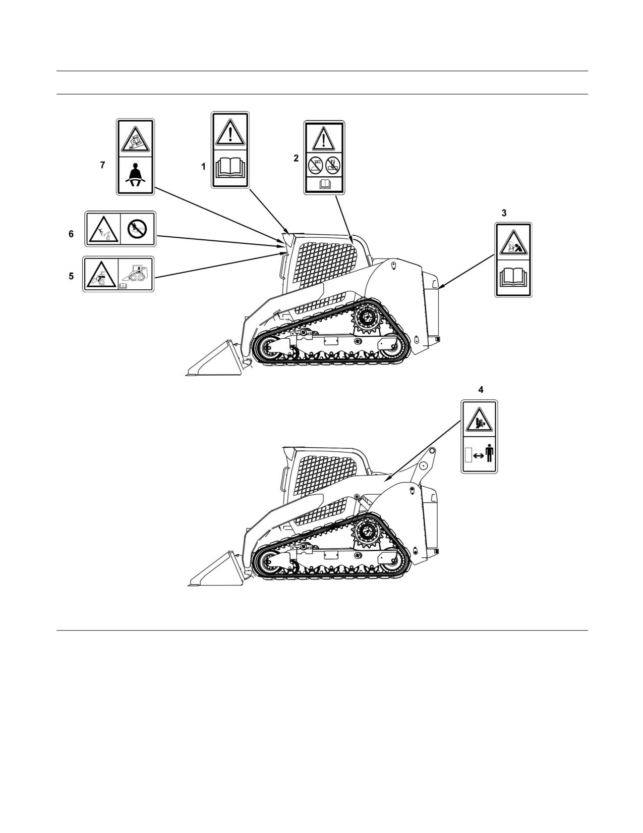
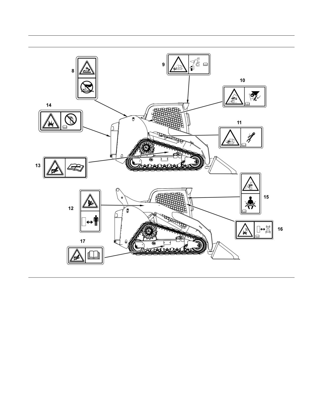
There are several specific safety messages on this
machine. The exact location of the hazards and
the description of the hazards are reviewed in this
section. Please become familiarized with all safety
messages.
Make sure that all of the safety messages are legible.
Clean the safety messages or replace the safety
messages if you cannot read the words. Replace
the illustrations if the illustrations are not legible.
When you clean the safety messages, use a cloth,
water and soap. Do not use solvent, gasoline, or
other harsh chemicals to clean the safety messages.
Solvents, gasoline, or harsh chemicals could loosen
the adhesive that secures the safety message. Loose
adhesive will allow the safety message to fall.
Replace any safety message that is damaged, or
missing. If a safety message is attached to a part
that is replaced, install a safety message on the
replacement part. Any Caterpillar dealer can provide
new safety messages.
SEBU8407-06
7
Safety Section
Safety Messages
g01451237
Illustration 2
(1) Do Not Operate.
(3) Jump Starting
(6) Never Permit Riders.
(2) Rollover Protective Structure/Falling
(4) Crushing Hazard
(7) Seat Belt
Object Protective Structure
(5) Stay Inside Operator Station
8
SEBU8407-06
Safety Section
Safety Messages
g01451239
Illustration 3
(8) Pressurized System
(12) Crushing Hazard
(16) Product Link
(9) Work Tool Coupler
(13) Accumulator
(17) High Pressure Oil
(10) Cab Support
(14) Aerosol Starting Aid
(11) Brace for the Loader Lift Arms
(15) Armrests
SEBU8407-06
9
Safety Section
Safety Messages
Do Not Operate (1)
Rollover Protective Structure/
Falling Object Protective Structure
This warning message is located on the front panel
by the rear view mirror.
(2)
This warning film and the certification film are located
inside the cab on the rear left side.
g01212168
g01379128
Structural damage, an overturn, modification, al-
teration, or improper repair can impair this struc-
ture's protection capability thereby voiding this
certification. Do not weld on or drill holes in the
Read and understand the instructions and warn-
structure. Consult a Caterpillar dealer to deter-
ings in the operation and maintenance manuals.
mine this structure's limitations without voiding
Contact any Caterpillar dealer for replacement
its certification.
manuals. Proper care is your responsibility.
Be alert! Know work conditions. Note and avoid all
This machine has been certified to the standards that
hazards and obstructions. Keep by-standers away
are listed on the certification plate. The maximum
when operating.
mass of the machine, which includes the operator
and the attachments without a payload, should not
Fasten seat belt and lower armrest.
exceed the mass on the certification film.
Make certain all controls are in neutral position
and start engine.
Disengage parking brake.
Machine controls are active.
Failure to follow the instructions or heed the warn-
ings could result injury or death.
10
SEBU8407-06
Safety Section
Safety Messages
Batteries (3)
Crush Hazard (4) & (12)
This warning message is located on the rear door on
This warning is located on the loader arms of the
the left side of the machine near the positive cable
machines that are equipped with vertical lift.
terminal.
g01378775
g01409730
No clearance for person in this area during oper-
Improper jumper cable connections can cause ex-
ation. Severe injury or death from crushing could
plosion resulting in personal injury. Batteries may
occur. Stay away from the work tool while it is in
be located in separate compartments, always con-
operation.
nect positive (+) cable to positive (+) terminal of
battery connected to starter solenoid and negative
(-) cable from external source to engine block or
frame.
SEBU8407-06
11
Safety Section
Safety Messages
Stay Inside Operator Station (5)
Never Permit Riders (6)
This warning message is located on the front panel
This warning message is located inside the cab on
by the rear view mirror.
the right side by the gauges.
g01427449
g01427444
Keep your body inside the operator station while
Never permit riders.
operating the loader.
Never use work tool for a work platform.
Never work with your arms, feet or legs beyond
the operator station.
Failure to follow the instructions or heed the warn-
ings could result in injury or death.
Failure to follow the instructions or heed the warn-
ings will result in injury or death.
12
SEBU8407-06
Safety Section
Safety Messages
Seat Belt (7)
Pressurized System (8)
This warning message is located on the ROPS post
This warning message is located on the right side of
on the right side .
the radiator by the radiator cap.
g01371636
g01378799
A seat belt should be worn at all times during ma-
Pressurized system: Hot coolant can cause seri-
chine operation to prevent serious injury or death
ous burn. To open cap, stop engine, wait until ra-
in the event of an accident or machine overturn.
diator is cool. Then loosen cap slowly to relieve
Failure to wear a seat belt during machine opera-
the pressure.
tion may result in serious injury or death.
Refer to Operation and Maintenance Manual, “Seat
Belt” for more information.
SEBU8407-06
13
Safety Section
Safety Messages
Work Tool Coupler (9)
Cab Support (10)
This warning message is located inside the cab on
This warning message is located on the right side of
the left side by the gauges.
the machine near the cab support lever.
g01427447
g01427441
Improper Attachment of the Work Tool could result
Do not go beneath cab unless cab is empty and
in injury or death.
support lever is engaged.
Do not operate the machine without confirmation
Failure to follow the instructions or heed the warn-
that the coupler pins are fully engaged. Follow the
ings could result in injury or death.
operating procedures in the Operation and Main-
tenance Manual.
Brace for the Loader Lift Arms (11)
Refer to Operation and Maintenance Manual, “Work
This warning message is located on the right hand
Tool Coupler Operation” for the proper procedure for
side on the brace for the loader lift arms.
the work tool coupler.
g01427443
Loader lift arm brace must be in place when work-
ing under raised lift arms.
Failure to follow the instructions or heed the warn-
ings could result in injury or death.
Refer to Operation and Maintenance Manual, “Loader
Lift Arm Brace Operation” for operating information.
14
SEBU8407-06
Safety Section
Safety Messages
Accumulator (13)
Armrests (15)
This warning message is located near the
This warning message is located inside the cab on
accumulator underneath the cab. If your machine is
the right side by the gauges.
equipped with ride control, there will be an additional
accumulator in this location.
g01372252
Accumulator may contain high pressure oil. Do
g01427454
not service the accumulator or any hydraulic lines
until all of the pressure has been relieved. See the
Service Manual for proper procedures. Failure to
heed this warning could result in injury or death.
Crush/Ejection Hazard! Could cause serious in-
jury or death.
Aerosol Starting Aid (14)
Always wear seatbelt and lower both armrests
while operating machine. Read the Operation and
This warning message is located on the side of the
Maintenance Manual.
air cleaner housing.
g01372254
Do not use ether. This machine is equipped with
glow plugs. Using ether can create explosions or
fires that can cause personal injury or death. Read
and follow the engine starting procedure in the
Operation and Maintenance Manual.
SEBU8407-06
15
Safety Section
Safety Messages
Product Link (16)
High Pressure Grease (17)
This safety message is located inside the cab on the
This safety message is located on the undercarriage
right hand window.
by the access panel.
g01370917
g01371642
This machine is equipped with a Caterpillar Prod-
Personal injury can result from grease under high
uct Link communication device which must be de-
pressure.
activated within 12 m (40 ft) of a blast zone. Failure
to do so could result in serious injury or death.
The adjuster cylinder for the track is under high
hydraulic pressure. Grease under high pressure
can cause injury.
Do not visually inspect the adjuster cylinder to see
if grease is released when the valve is opened.
Look to see that the track has loosened.
Refer to Operation and Maintenance Manual, “Track
- Inspect/Adjust (Detension the Track)” for more
information.
i02811655
Safety Messages
(Work Tools)
SMCS Code: 7000; 7405
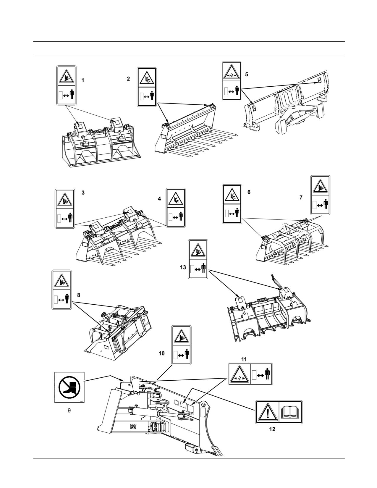
There are several specific safety messages on these
work tools. The exact location of the hazards and
the description of the hazards are reviewed in this
section. Please become familiarized with all safety
messages.
16
SEBU8407-06
Safety Section
Safety Messages
Make sure that all of the safety messages are legible.
Clean the safety messages or replace the safety
messages if you cannot read the words. Replace
the illustrations if the illustrations are not legible.
When you clean the safety messages, use a cloth,
water and soap. Do not use solvent, gasoline, or
other harsh chemicals to clean the safety messages.
Solvents, gasoline, or harsh chemicals could loosen
the adhesive that secures the safety message. Loose
adhesive will allow the safety message to fall.
Replace any safety message that is damaged, or
missing. If a safety message is attached to a part
that is replaced, install a safety message on the
replacement part. Any Caterpillar dealer can provide
new safety messages.
SEBU8407-06
17
Safety Section
Safety Messages
g01402473
Illustration 4
18
SEBU8407-06
Safety Section
Safety Messages
Industrial Grapple Bucket (1)
Utility Fork (2)
These warning messages are located on top of the
These warning messages are located on top of the
guards for the grapple cylinders.
fork carriage.
g01378775
g01389170
No clearance for person in this area during oper-
No clearance for person in this area during op-
ation. Severe injury or death from crushing could
eration. Severe injury or death from impalement
occur. Stay away from the work tool while it is in
could occur. Stay away from the work tool while it
operation.
is in operation.
SEBU8407-06
19
Safety Section
Safety Messages
Industrial Grapple Fork (3)
Industrial Grapple Fork (4)
These warning messages are located on the guards
These warning messages are located on top of the
for the grapple cylinders.
fork carriage.
g01378775
g01389170
No clearance for person in this area during oper-
No clearance for person in this area during op-
ation. Severe injury or death from crushing could
eration. Severe injury or death from impalement
occur. Stay away from the work tool while it is in
could occur. Stay away from the work tool while it
operation.
is in operation.
20
SEBU8407-06
Safety Section
Safety Messages
Angle Blade (5)
Utility Grapple Fork (6)
These warning messages are located on the back
These warning messages are located on top of the
side of the blade.
fork carriage.
g01377717
g01389170
No clearance for person in this area during oper-
No clearance for person in this area during op-
ation. Severe injury or death from crushing could
eration. Severe injury or death from impalement
occur. Stay away from the work tool while it is in
could occur. Stay away from the work tool while it
operation.
is in operation.
SEBU8407-06
21
Safety Section
Safety Messages
Utility Grapple Fork (7)
Utility Grapple Bucket (8)
These warning messages are located on top of the
These warning messages are located on top of the
grapple frame.
grapple frame.
g01378775
g01378775
No clearance for person in this area during oper-
No clearance for person in this area during oper-
ation. Severe injury or death from crushing could
ation. Severe injury or death from crushing could
occur. Stay away from the work tool while it is in
occur. Stay away from the work tool while it is in
operation.
operation.
Dozer Blade (9)
This warning message is located on top of the dozer
blade.
g00946617
Falling Hazard - Area may be oily and slippery.
Do not step on cylinders. Serious injury or death
could occur from a fall.
22
SEBU8407-06
Safety Section
Safety Messages
Dozer Blade (10)
Dozer Blade (11)
This warning message is located on top of the dozer
These warning messages are located on the back
blade.
side of the blade.
g01371644
No clearance for person in this area during oper-
ation. Severe injury or death from crushing could
g01378775
occur. Stay away from the work tool while it is in
operation.
Dozer Blade (12)
No clearance for person in this area during oper-
ation. Severe injury or death from crushing could
This warning is located on right hand side on the
occur. Stay away from the work tool while it is in
back of the blade.
operation.
g01370904
DO NOT OPERATE OR WORK ON THIS MACHINE
UNLESS YOU HAVE READ AND UNDERSTAND
THE INSTRUCTIONS AND WARNINGS IN THE
OPERATION AND MAINTENANCE MANUALS.
FAILURE TO FOLLOW THE INSTRUCTIONS OR
HEED THE WARNINGS COULD RESULT IN IN-
JURY OR DEATH. CONTACT ANY CATERPILLAR
DEALER FOR REPLACEMENT MANUALS. PROP-
ER CARE IS YOUR RESPONSIBILITY.
SEBU8407-06
23
Safety Section
Additional Messages
Grapple Rake (13)
Consult your Caterpillar dealer for replacement of
messages.
These warning messages are located on top of the
grapple frame.
Product Link (If Equipped)
g01418953
Illustration 5
If your machine is equipped with the Product Link
System, this film will be located in the cab. The
Product Link System is a satellite communication
device that transmits information regarding the
g01378775
machine back to Caterpillar and Caterpillar dealers
and customers. All logged events and diagnostic
codes that are available to the Caterpillar Electronic
Technician (ET) on the CAT data link can be sent
No clearance for person in this area during oper-
to the satellite. Information can also be sent to the
ation. Severe injury or death from crushing could
Product Link System. The information is used to
occur. Stay away from the work tool while it is in
improve Caterpillar products and Caterpillar services.
operation.
Refer to Operation and Maintenance Manual,
“Product Link” for more information.
i02900018
i04010649
Additional Messages
General Hazard Information
SMCS Code: 7000; 7405
SMCS Code: 7000
There are several specific messages on this machine.
Please become familiarized with all messages.
Make sure that all of the messages are legible. Clean
the messages or replace the messages if you cannot
read the words.
When you clean the messages, use a cloth, water
and soap. Do not use solvent, gasoline, or other
harsh chemicals to clean the messages. Solvents,
gasoline, or harsh chemicals could loosen the
adhesive that secures the messages. Loose adhesive
will allow the messages to fall.
Replace the illustrations if the illustrations are not
legible. Replace any message that is damaged, or
g00104545
Illustration 6
missing. If a message is attached to a part that is
replaced, install a message on the replacement part.
24
SEBU8407-06
Safety Section
General Hazard Information
Attach a “Do Not Operate” warning tag or a similar
Do not smoke when you service an air conditioner.
warning tag to the start switch or to the controls.
Also, do not smoke if refrigerant gas may be present.
Attach the warning tag before you service the
Inhaling the fumes that are released from a flame that
equipment or before you repair the equipment. These
contacts air conditioner refrigerant can cause bodily
warning tags (Special Instruction, SEHS7332) are
harm or death. Inhaling gas from air conditioner
available from your Cat dealer.
refrigerant through a lighted cigarette can cause
bodily harm or death.
Never put maintenance fluids into glass containers.
Drain all liquids into a suitable container.
Operating the machine while distracted can result
in the loss of machine control. Use extreme cau-
Obey all local regulations for the disposal of liquids.
tion when using any device while operating the
machine. Operating the machine while distracted
Use all cleaning solutions with care. Report all
can result in personal injury or death.
necessary repairs.
Know the width of your equipment in order to maintain
Do not allow unauthorized personnel on the
proper clearance when you operate the equipment
equipment.
near fences or near boundary obstacles.
Unless you are instructed otherwise, perform
Be aware of high voltage power lines and power
maintenance with the equipment in the servicing
cables that are buried. If the machine comes in
position. Refer to Operation and Maintenance Manual
contact with these hazards, serious injury or death
for the procedure for placing the equipment in the
may occur from electrocution.
servicing position.
When you perform maintenance above ground level,
use appropriate devices such as ladders or man lift
machines. If equipped, use the machine anchorage
points and use approved fall arrest harnesses and
lanyards.
Pressurized Air and Water
Pressurized air and/or water can cause debris and/or
hot water to be blown out. The debris and/or hot
water could result in personal injury.
When pressurized air and/or pressurized water is
used for cleaning, wear protective clothing, protective
g00702020
Illustration 7
shoes, and eye protection. Eye protection includes
goggles or a protective face shield.
Wear a hard hat, protective glasses, and other
protective equipment, as required.
The maximum air pressure for cleaning purposes
must be reduced to 205 kPa (30 psi) when the
Do not wear loose clothing or jewelry that can snag
nozzle is deadheaded and the nozzle is used with
on controls or on other parts of the equipment.
an effective chip deflector and personal protective
equipment. The maximum water pressure for
Make sure that all protective guards and all covers
cleaning purposes must be below 275 kPa (40 psi).
are secured in place on the equipment.
Keep the equipment free from foreign material.
Trapped Pressure
Remove debris, oil, tools, and other items from the
deck, from walkways, and from steps.
Pressure can be trapped in a hydraulic system.
Releasing trapped pressure can cause sudden
Secure all loose items such as lunch boxes, tools,
machine movement or attachment movement. Use
and other items that are not a part of the equipment.
caution if you disconnect hydraulic lines or fittings.
High-pressure oil that is released can cause a hose
Know the appropriate work site hand signals and
to whip. High-pressure oil that is released can cause
the personnel that are authorized to give the hand
oil to spray. Fluid penetration can cause serious
signals. Accept hand signals from one person only.
injury and possible death.
SEBU8407-06
25
Safety Section
General Hazard Information
Fluid Penetration
Inhalation
Pressure can be trapped in the hydraulic circuit long
after the engine has been stopped. The pressure can
cause hydraulic fluid or items such as pipe plugs to
escape rapidly if the pressure is not relieved correctly.
Do not remove any hydraulic components or parts
until pressure has been relieved or personal injury
may occur. Do not disassemble any hydraulic
components or parts until pressure has been relieved
or personal injury may occur. Refer to the Service
Manual for any procedures that are required to
relieve the hydraulic pressure.
g02159053
Illustration 9
Exhaust
Use caution. Exhaust fumes can be hazardous
to your health. If you operate the machine in an
enclosed area, adequate ventilation is necessary.
Asbestos Information
Cat equipment and replacement parts that are
shipped from Caterpillar are asbestos free.
Caterpillar recommends the use of only genuine
g00687600
Illustration 8
Cat replacement parts. Use the following guidelines
when you handle any replacement parts that contain
Always use a board or cardboard when you check
asbestos or when you handle asbestos debris.
for a leak. Leaking fluid that is under pressure can
penetrate body tissue. Fluid penetration can cause
Use caution. Avoid inhaling dust that might be
serious injury and possible death. A pin hole leak can
generated when you handle components that contain
cause severe injury. If fluid is injected into your skin,
asbestos fibers. Inhaling this dust can be hazardous
you must get treatment immediately. Seek treatment
to your health. The components that may contain
from a doctor that is familiar with this type of injury.
asbestos fibers are brake pads, brake bands, lining
material, clutch plates, and some gaskets. The
Containing Fluid Spillage
asbestos that is used in these components is bound
in a resin or sealed in some way. Normal handling
Care must be taken in order to ensure that fluids
is not hazardous unless airborne dust that contains
are contained during performance of inspection,
asbestos is generated.
maintenance, testing, adjusting, and repair of the
equipment. Prepare to collect the fluid with suitable
If dust that may contain asbestos is present, there
containers before opening any compartment or
are several guidelines that should be followed:
disassembling any component that contains fluids.
• Never use compressed air for cleaning.
Refer to Special Publication, NENG2500, “Caterpillar
Dealer Service Tool Catalog” for the following items:
• Avoid brushing materials that contain asbestos.
• Tools that are suitable for collecting fluids and
• Avoid grinding materials that contain asbestos.
equipment that is suitable for collecting fluids
•
Use a wet method in order to clean up asbestos
materials.
• Tools that are suitable for containing fluids and
equipment that is suitable for containing fluids
•
A vacuum cleaner that is equipped with a high
Obey all local regulations for the disposal of liquids.
efficiency particulate air filter (HEPA) can also be
used.
26
SEBU8407-06
Safety Section
Crushing Prevention and Cutting Prevention
• Use exhaust ventilation on permanent machining
Unless you are instructed otherwise, never attempt
jobs.
adjustments while the machine is moving or while
the engine is running.
• Wear an approved respirator if there is no other
way to control the dust.
Never jump across the starter solenoid terminals
in order to start the engine. Unexpected machine
• Comply with applicable rules and regulations
movement could result.
for the work place. In the United States, use
Occupational Safety and Health Administration
Whenever there are equipment control linkages the
(OSHA) requirements. These OSHA requirements
clearance in the linkage area will change with the
can be found in “29 CFR 1910.1001”.
movement of the equipment or the machine. Stay
clear of areas that may have a sudden change in
• Obey environmental regulations for the disposal
clearance with machine movement or equipment
of asbestos.
movement.
• Stay away from areas that might have asbestos
Stay clear of all rotating and moving parts.
particles in the air.
If it is necessary to remove guards in order to perform
maintenance, always install the guards after the
Dispose of Waste Properly
maintenance is performed.
Keep objects away from moving fan blades. The fan
blade will throw objects or cut objects.
Do not use a kinked wire cable or a frayed wire cable.
Wear gloves when you handle wire cable.
When you strike a retainer pin with force, the retainer
pin can fly out. The loose retainer pin can injure
personnel. Make sure that the area is clear of people
when you strike a retainer pin. To avoid injury to
your eyes, wear protective glasses when you strike
a retainer pin.
g00706404
Chips or other debris can fly off an object when you
Illustration 10
strike the object. Make sure that no one can be
injured by flying debris before striking any object.
Improperly disposing of waste can threaten the
environment. Potentially harmful fluids should be
disposed of according to local regulations.
i04760300
Always use leakproof containers when you drain
Burn Prevention
fluids. Do not pour waste onto the ground, down a
drain, or into any source of water.
SMCS Code: 7000
Do not touch any part of an operating engine.
i01359664
Allow the engine to cool before any maintenance is
performed on the engine. Relieve all pressure in the
Crushing Prevention and
air system, in the oil system, in the lubrication system,
Cutting Prevention
in the fuel system, or in the cooling system before
any lines, fittings, or related items are disconnected.
SMCS Code: 7000
Coolant
Support the equipment properly before you perform
any work or maintenance beneath that equipment.
When the engine is at operating temperature, the
Do not depend on the hydraulic cylinders to hold
engine coolant is hot. The coolant is also under
up the equipment. Equipment can fall if a control is
pressure. The radiator and all lines to the heaters or
moved, or if a hydraulic line breaks.
to the engine contain hot coolant.
Do not work beneath the cab of the machine unless
Any contact with hot coolant or with steam can cause
the cab is properly supported.
severe burns. Allow cooling system components to
cool before the cooling system is drained.
SEBU8407-06
27
Safety Section
Fire Prevention and Explosion Prevention
Check the coolant level only after the engine has
General
been stopped.
All fuels, most lubricants, and some coolant mixtures
Ensure that the filler cap is cool before removing the
are flammable.
filler cap. The filler cap must be cool enough to touch
with a bare hand. Remove the filler cap slowly in
To minimize the risk of fire or explosion, Caterpillar
order to relieve pressure.
recommends the following actions.
Cooling system conditioner contains alkali. Alkali can
Always perform a Walk-Around Inspection, which
cause personal injury. Do not allow alkali to contact
may help you identify a fire hazard. Do not operate a
the skin, the eyes, or the mouth.
machine when a fire hazard exists. Contact your Cat
dealer for service.
Oils
Understand the use of the primary exit and alternative
exit on the machine. Refer to Operation and
Hot oil and hot components can cause personal
Maintenance Manual, “Alternative Exit”.
injury. Do not allow hot oil to contact the skin. Also,
do not allow hot components to contact the skin.
Do not operate a machine with a fluid leak. Repair
leaks and clean up fluids before resuming machine
Remove the hydraulic tank filler cap only after the
operation. Fluids that are leaking or spilled onto hot
engine has been stopped. The filler cap must be
surfaces or onto electrical components can cause a
cool enough to touch with a bare hand. Follow the
fire. A fire may cause personal injury or death.
standard procedure in this manual in order to remove
the hydraulic tank filler cap.
Remove flammable material such as leaves,
twigs, papers, trash, and so on. These items may
Batteries
accumulate in the engine compartment or around
other hot areas and hot parts on the machine.
The liquid in a battery is an electrolyte. Electrolyte is
an acid that can cause personal injury. Do not allow
Keep the access doors to major machine
electrolyte to contact the skin or the eyes.
compartments closed and access doors in working
condition in order to permit the use of fire suppression
Do not smoke while checking the battery electrolyte
equipment, in case a fire should occur.
levels. Batteries give off flammable fumes which can
explode.
Clean all accumulations of flammable materials such
as fuel, oil, and debris from the machine.
Always wear protective glasses when you work with
batteries. Wash hands after touching batteries. The
Do not operate the machine near any flame.
use of gloves is recommended.
Keep shields in place. Exhaust shields (if equipped)
protect hot exhaust components from oil spray or fuel
i04218233
spray in case of a break in a line, in a hose, or in a
seal. Exhaust shields must be installed correctly.
Fire Prevention and Explosion
Prevention
Do not weld or flame cut on tanks or lines that contain
flammable fluids or flammable material. Empty and
SMCS Code: 7000
purge the lines and tanks. Then clean the lines and
tanks with a nonflammable solvent prior to welding
or flame cutting. Ensure that the components are
properly grounded in order to avoid unwanted arcs.
Dust that is generated from repairing nonmetallic
hoods or fenders may be flammable and/or explosive.
Repair such components in a well ventilated area
away from open flames or sparks. Use suitable
Personal Protection Equipment (PPE).
g00704000
Illustration 11
28
SEBU8407-06
Safety Section
Fire Prevention and Explosion Prevention
Inspect all lines and hoses for wear or deterioration.
Battery and Battery Cables
Replace damaged lines and hoses. The lines and
the hoses should have adequate support and secure
clamps. Tighten all connections to the recommended
torque. Damage to the protective cover or insulation
may provide fuel for fires.
Store fuels and lubricants in properly marked
containers away from unauthorized personnel. Store
oily rags and flammable materials in protective
containers. Do not smoke in areas that are used for
storing flammable materials.
g02298225
Illustration 13
Caterpillar recommends the following in order to
minimize the risk of fire or an explosion related to
the battery.
Do not operate a machine if battery cables or related
parts show signs of wear or damage. Contact your
Cat dealer for service.
Follow safe procedures for engine starting with
g00704059
Illustration 12
jump-start cables. Improper jumper cable connections
can cause an explosion that may result in injury.
Use caution when you are fueling a machine. Do not
Refer to Operation and Maintenance Manual,
smoke while you are fueling a machine. Do not fuel
“Engine Starting with Jump Start Cables” for specific
a machine near open flames or sparks. Always stop
instructions.
the engine before fueling. Fill the fuel tank outdoors.
Properly clean areas of spillage.
Do not charge a frozen battery. This may cause an
explosion.
Never store flammable fluids in the operator
compartment of the machine.
Gases from a battery can explode. Keep any open
flames or sparks away from the top of a battery. Do
not smoke in battery charging areas.
Never check the battery charge by placing a metal
object across the terminal posts. Use a voltmeter in
order to check the battery charge.
Daily inspect battery cables that are in areas that
are visible. Inspect cables, clips, straps, and other
restraints for damage. Replace any damaged parts.
Check for signs of the following, which can occur
over time due to use and environmental factors:
• Fraying
• Abrasion
• Cracking
SEBU8407-06
29
Safety Section
Fire Prevention and Explosion Prevention
• Discoloration
Attaching electrical wiring to hoses and tubes that
contain flammable fluids or combustible fluids should
• Cuts on the insulation of the cable
be avoided.
• Fouling
Consult your Cat dealer for repair or for replacement
parts.
• Corroded terminals, damaged terminals, and loose
terminals
Keep wiring and electrical connections free of debris.
Replace damaged battery cable(s) and replace
Lines, Tubes, and Hoses
any related parts. Eliminate any fouling, which may
have caused insulation failure or related component
Do not bend high-pressure lines. Do not strike
damage or wear. Ensure that all components are
high-pressure lines. Do not install any lines that
reinstalled correctly.
are bent or damaged. Use the appropriate backup
wrenches in order to tighten all connections to the
An exposed wire on the battery cable may cause
recommended torque.
a short to ground if the exposed area comes into
contact with a grounded surface. A battery cable
short produces heat from the battery current, which
may be a fire hazard.
An exposed wire on the ground cable between the
battery and the disconnect switch may cause the
disconnect switch to be bypassed if the exposed area
comes into contact with a grounded surface. This
may result in an unsafe condition for servicing the
machine. Repair components or replace components
before servicing the machine.
g00687600
Illustration 14
Fire on a machine can result in personal injury
or death. Exposed battery cables that come into
Check lines, tubes, and hoses carefully. Wear
contact with a grounded connection can result in
Personal Protection Equipment (PPE) in order to
fires. Replace cables and related parts that show
check for leaks. Always use a board or cardboard
signs of wear or damage. Contact your Cat dealer.
when you check for a leak. Leaking fluid that is under
pressure can penetrate body tissue. Fluid penetration
can cause serious injury and possible death. A pin
Wiring
hole leak can cause severe injury. If fluid is injected
into your skin, you must get treatment immediately.
Check electrical wires daily. If any of the following
Seek treatment from a doctor that is familiar with this
conditions exist, replace parts before you operate
type of injury.
the machine.
Replace the affected parts if any of the following
• Fraying
conditions are present:
• Signs of abrasion or wear
• End fittings are damaged or leaking.
• Cracking
• Outer coverings are chafed or cut.
• Discoloration
• Wires are exposed.
• Cuts on insulation
• Outer coverings are swelling or ballooning.
• Other damage
• Flexible parts of the hoses are kinked.
Make sure that all clamps, guards, clips, and straps
are reinstalled correctly. This will help to prevent
• Outer covers have exposed embedded armoring.
vibration, rubbing against other parts, and excessive
heat during machine operation.
• End fittings are displaced.
30
SEBU8407-06
Safety Section
Fire Safety
Make sure that all clamps, guards, and heat shields
i04025591
are installed correctly. During machine operation, this
Fire Safety
will help to prevent vibration, rubbing against other
parts, excessive heat, and failure of lines, tubes, and
SMCS Code: 1000; 6700; 7000
hoses.
Note: Locate secondary exits and how to use the
Do not operate a machine when a fire hazard
secondary exits before you operate the machine.
exists. Repair any lines that are corroded, loose,
or damaged. Leaks may provide fuel for fires.
Note: Locate fire extinguishers and how to use a fire
Consult your Cat dealer for repair or for replacement
extinguisher before you operate the machine.
parts. Use genuine Cat parts or the equivalent, for
capabilities of both the pressure limit and temperature
If you find that you are involved in a machine fire, your
limit.
safety and that of others on site is the top priority.
The following actions should only be performed if the
Ether
actions do not present a danger or risk to you and
any nearby people. At all times you should assess
Ether (if equipped) is commonly used in cold-weather
the risk of personal injury and move away to a safe
applications. Ether is flammable and poisonous.
distance as soon as you feel unsafe.
Follow the correct cold engine starting procedures.
Move the machine away from nearby combustible
Refer to the section in the Operation and Maintenance
material such as fuel/oil stations, structures, trash,
Manual with the label “Engine Starting”.
mulch, and timber.
Do not spray ether manually into an engine if the
Lower any implements and turn off the engine as
machine is equipped with a thermal starting aid for
soon as possible. If you leave the engine running,
cold weather starting.
the engine will continue to feed a fire. The fire will
be fed from any damaged hoses that are attached
Use ether in well ventilated areas. Do not smoke
to the engine or pumps.
while you are replacing an ether cylinder or while you
are using an ether spray.
If possible, turn the battery disconnect switch to the
OFF position. Disconnecting the battery will remove
Do not store ether cylinders in living areas or in the
the ignition source in the event of an electrical short.
operator compartment of a machine. Do not store
Disconnecting the battery will eliminate a second
ether cylinders in direct sunlight or in temperatures
ignition source if electrical wiring is damaged by the
above 49° C (120.2° F). Keep ether cylinders away
fire, resulting in a short circuit.
from open flames or sparks.
Notify emergency personnel of the fire and your
Dispose of used ether cylinders properly. Do not
location.
puncture an ether cylinder. Keep ether cylinders
away from unauthorized personnel.
If your machine is equipped with a fire suppression
system, follow the manufacturers procedure for
Fire Extinguisher
activating the system.
As an additional safety measure, keep a fire
Note: Fire suppression systems need to be regularly
extinguisher on the machine.
inspected by qualified personnel. You must be trained
to operate the fire suppression system.
Be familiar with the operation of the fire extinguisher.
Inspect the fire extinguisher and service the fire
Use the on-board fire extinguisher and use the
extinguisher regularly. Follow the recommendations
following procedure:
on the instruction plate.
1. Pull the pin.
Consider installation of an aftermarket Fire
Suppression System, if the application and working
2. Aim the extinguisher or nozzle at the base of the
conditions warrant the installation.
fire.
3. Squeeze the handle and release the extinguishing
agent.
4. Sweep the extinguisher from side to side across
the base of the fire until the fire is out.
SEBU8407-06
31
Safety Section
Fire Extinguisher Location
Remember, if you are unable to do anything else,
i01122596
shut off the machine before exiting. By shutting off
Electrical Storm Injury
the machine, fuels will not continue to be pumped
into the fire.
Prevention
If the fire grows out of control, be aware of the
SMCS Code: 7000
following risks:
When lightning is striking in the vicinity of the
• Tires on wheeled machines pose a risk of explosion
machine, the operator should never attempt the
as tires burn. Hot shrapnel and debris can be
following procedures:
thrown great distances in an explosion.
Mount the machine.
•
• Tanks, accumulators, hoses, and fittings can
rupture in a fire, spraying fuels and shrapnel over a
• Dismount the machine.
large area.
If you are in the operator's station during an electrical
• Remember that nearly all of the fluids on the
storm, stay in the operator's station. If you are on the
machine are flammable, including coolant and oils.
ground during an electrical storm, stay away from
Additionally, plastics, rubbers, fabrics, and resins
the vicinity of the machine.
in fiberglass panels are also flammable.
i00771840
i02574390
Before Starting Engine
Fire Extinguisher Location
SMCS Code: 1000; 7000
SMCS Code: 7000; 7419
Start the engine only from the operator compartment.
Make sure that a fire extinguisher is on the
Never short across the starter terminals or across
machine. Make sure that you are familiar with the
the batteries. Shorting could damage the electrical
operation of the fire extinguisher. Inspect the fire
system by bypassing the engine neutral start system.
extinguisher and service the fire extinguisher. Obey
the recommendations on the instruction plate.
Inspect the condition of the seat belt and of the
mounting hardware. Replace any parts that are worn
or damaged. Regardless of appearance, replace the
seat belt after three years of use. Do not use a seat
belt extension on a retractable seat belt.
Adjust the seat so that full pedal travel can be
achieved with the operator's back against the back
of the seat.
Make sure that the machine is equipped with a
lighting system that is adequate for the job conditions.
Make sure that all machine lights are working
properly.
Before you start the engine and before you move the
machine, make sure that no one is underneath the
machine, around the machine, or on the machine.
Make sure that the area is free of personnel.
i03162317
g01289762
Illustration 15
Visibility Information
Mount the fire extinguisher on the left side of the
SMCS Code: 7000
cab behind the seat. Consult your Caterpillar dealer
for the proper procedure for mounting the fire
Before you start the machine, perform a walk-around
extinguisher.
inspection in order to ensure that there are no
hazards around the machine.
32
SEBU8407-06
Safety Section
Engine Starting
While the machine is in operation, constantly survey
Diesel engine exhaust contains products of
the area around the machine in order to identify
combustion which can be harmful to your health.
potential hazards as hazards become visible around
Always start the engine in a well ventilated area.
the machine.
Always operate the engine in a well ventilated area.
If you are in an enclosed area, vent the exhaust to
Your machine may be equipped with visual aids.
the outside.
Some examples of visual aids are Closed Circuit
Television (CCTV) and mirrors. Before operating the
i02680030
machine, ensure that the visual aids are in proper
working condition and that the visual aids are clean.
Before Operation
Adjust the visual aids using the procedures that are
located in this Operation and Maintenance Manual.
SMCS Code: 7000
If equipped, the Work Area Vision System shall be
adjusted according to Operation and Maintenance
Video tapes and safety information are available
Manual, SEBU8157, “Work Area Vision System”.
in English for the machine. A list of some of
the material is available in the Operation and
It may not be possible to provide direct visibility on
Maintenance Manual, “Reference Material”. Consult
large machines to all areas around the machine.
your Caterpillar dealer in order to obtain copies of
Appropriate job site organization is required in order
the material. The information should be reviewed by
to minimize hazards that are caused by restricted
every person that operates the machine.
visibility. Job site organization is a collection of rules
and procedures that coordinates machines and
Clear all personnel from the machine and from the
people that work together in the same area. Examples
area.
of job site organization include the following:
Clear all obstacles from the path of the machine.
• Safety instructions
Beware of hazards such as wires, ditches, etc.
• Controlled patterns of machine movement and
Make sure that all windows are clean. Secure all
vehicle movement
doors in the closed position. Secure the windows in
the open position or in the shut position.
• Workers that direct traffic to move when it is safe
Make sure that the machine horn, the backup alarm
• Restricted areas
and all other warning devices are working properly.
• Operator training
Fasten the seat belt securely. Lower the armrests.
• Warning symbols or warning signs on machines
or on vehicles
i03713960
Operation
• A system of communication
SMCS Code: 7000
• Communication between workers and operators
prior to approaching the machine
Only operate the machine while you are in the seat.
The seat belt must be fastened while you operate the
Modifications of the machine configuration by the
machine. Only operate the controls while the engine
user that result in a restriction of visibility shall be
is running.
evaluated.
Before you move the machine, you must be certain
i02578915
that no one will be endangered.
Engine Starting
While you operate the machine and the work tool
slowly in an open area, check for proper operation of
SMCS Code: 1000; 7000
all controls and all protective devices.
If a warning tag is attached to the start switch or to
Do not allow riders on the machine. Never use the
the controls, do not start the engine. Also, do not
work tool for a work platform.
move any controls.
Note any needed repairs during machine operation.
Move all hydraulic controls to the NEUTRAL position
Report any needed repairs.
before you start the engine.
SEBU8407-06
33
Safety Section
Work Tools
Use Caterpillar Approved Work Tools on this
Keep all windows and doors closed on the host
machine. Obey all the lift restrictions. Refer to
machine. Always wear protective glasses. Always
Operation and Maintenance Manual, “Caterpillar
wear the protective equipment that is recommended
Approved Work Tools” for the approved work tools
in the work tool's operation manual. Wear any other
and the lift restriction information.
protective equipment that is required for the operating
environment.
Carry work tools low. Lower the lift arms fully. Tilt
back the work tool in order to keep the work tool off
To prevent personnel from being struck by flying
of the ground. Do not go close to the edge of a cliff,
objects, ensure that all personnel are out of the work
an excavation, or an overhang.
area.
If the machine begins to sideslip downward on a
While you are performing any maintenance, any
grade, immediately remove the load and turn the
testing, or any adjustments to the work tool stay
machine downhill.
clear of the following areas: cutting edges, pinching
surfaces, and crushing surfaces.
Avoid any conditions that can lead to tipping the
machine. The machine can tip when you work on
i02518481
hills, on banks and on slopes. Also, the machine
can tip when you cross ditches, ridges or other
Parking
unexpected obstacles.
SMCS Code: 7000
Avoid operating the machine across the slope. When
possible, operate the machine up the slopes and
Park on a level surface. If you must park on a grade,
down the slopes.
chock the machine.
Maintain control of the machine. Do not overload the
1. Move the joystick control slowly to the NEUTRAL
machine beyond the machine capacity.
position in order to stop the machine.
Never straddle a wire cable. Never allow personnel
2. Move the governor control lever to the LOW IDLE
to straddle a wire cable.
position.
Know the maximum dimensions of your machine.
3. Lower the loader arms and tilt the linkage so that
the work tool rests firmly on the ground.
Always keep the Rollover Protective Structure
(ROPS) installed during machine operation.
4. Move the hydraulic controls to the NEUTRAL
position.
This machine is designed to operate in the ambient
temperature range of -32 °C (-25 °F) to 43 °C
5. Turn the engine start switch key to OFF position
(109.4 °F).
and remove the key.
Observe all applicable local government regulations
6. Raise the armrests and exit the machine.
when you use the Skid Steer Loader to lift heavy
objects.
i03745198
i01115299
Slope Operation
Work Tools
SMCS Code: 7000
SMCS Code: 6700
Machines that are operating safely in various
applications depend on these criteria: the machine
Only use work tools that are approved by Caterpillar
model, configuration, machine maintenance,
for use on Caterpillar machines. Refer to the
operating speed of the machine, conditions of the
Operation and Maintenance Manual, “Caterpillar
terrain, fluid levels, and tire inflation pressures. The
Approved Work Tools”.
most important criteria are the skill and judgment of
the operator.
If you are in doubt about the compatibility of a
particular work tool with your machine, consult your
Caterpillar dealer.
Make sure that all necessary guarding is in place on
the host machine and on the work tool.
34
SEBU8407-06
Safety Section
Equipment Lowering with Engine Stopped
A well trained operator that follows the instructions
Operating techniques - Keep all attachments or
in the Operation and Maintenance Manual has
pulled loads low to the ground for optimum stability.
the greatest impact on stability. Operator training
provides a person with the following abilities:
Machine systems have limitations on slopes -
observation of working and environmental conditions,
Slopes can affect the proper function and operation
feel for the machine, identification of potential
of the various machine systems. These machine
hazards, and operating the machine safely by making
systems are needed for machine control.
appropriate decisions.
Note: Safe operation on steep slopes may require
When you work on side hills and when you work on
special machine maintenance. Excellent skill of
slopes, consider the following important points:
the operator and proper equipment for specific
applications are also required. Consult the Operation
Speed of travel - At higher speeds, forces of inertia
and Maintenance Manual sections for the proper fluid
tend to make the machine less stable.
level requirements and intended machine use.
Roughness of terrain or surface - The machine
i01329161
may be less stable with uneven terrain.
Equipment Lowering with
Direction of travel - Avoid operating the machine
across the slope. When possible, operate the
Engine Stopped
machine up the slopes and operate the machine
down the slopes. Place the heaviest end of the
SMCS Code: 7000
machine uphill when you are working on an incline.
Before lowering any equipment with the engine
Mounted equipment - Balance of the machine
stopped, clear the area around the equipment of
may be impeded by the following components:
all personnel. The procedure to use will vary with
equipment that is mounted on the machine, machine
the type of equipment to be lowered. Keep in mind
configuration, weights, and counterweights.
most systems use a high pressure fluid or air to
raise or lower equipment. The procedure will cause
Nature of surface - Ground that has been newly
high pressure air, hydraulic, or some other media
filled with earth may collapse from the weight of the
to be released in order to lower the equipment.
machine.
Wear appropriate personal protective equipment and
follow the established procedure in the Operation
Surface material - Rocks and moisture of the
and Maintenance Manual, “Equipment Lowering with
surface material may drastically affect the machine's
Engine Stopped” in the Operation Section of the
traction and machine's stability. Rocky surfaces may
manual.
promote side slipping of the machine.
i03064142
Slippage due to excessive loads - This may cause
downhill tracks or downhill tires to dig into the ground,
Sound Information and
which will increase the angle of the machine.
Vibration Information
Width of tracks or tires - Narrower tracks or
narrower tires further increase the digging into the
SMCS Code: 7000
ground which causes the machine to be less stable.
Sound Level Information
Implements attached to the drawbar - This may
decrease the weight on the uphill tracks. This may
The operator Equivalent Sound Pressure Level
also decrease the weight on the uphill tires. The
(Leq) is 87 dB(A) when “ANSI/SAE J1166 OCT 98”
decreased weight will cause the machine to be less
is used to measure the value for an enclosed cab.
stable.
This is a work cycle sound exposure level. The cab
was properly installed and maintained. The test was
Height of the working load of the machine -
conducted with the cab doors and the cab windows
When the working loads are in higher positions, the
closed.
stability of the machine is reduced.
Operated equipment - Be aware of performance
features of the equipment in operation and the effects
on machine stability.
SEBU8407-06
35
Safety Section
Sound Information and Vibration Information
Hearing protection may be needed when the
It is not possible to get precise vibration levels for
machine is operated with an open operator station for
this machine. The expected vibration levels can be
extended periods or in a noisy environment. Hearing
estimated with the information in Table 1 in order
protection may be needed when the machine is
to calculate the daily vibration exposure. A simple
operated with a cab that is not properly maintained or
evaluation of the machine application can be used.
when the doors and windows are open for extended
periods or in a noisy environment.
Estimate the vibration levels for the three vibration
directions. For typical operating conditions, use the
The average exterior sound pressure level is 75
average vibration levels as the estimated level. With
dB(A) when the “SAE J88Apr95 - Constant Speed
an experienced operator and smooth terrain, subtract
Moving Test” procedure is used to measure the value
the Scenario Factors from the average vibration level
for the standard machine. The measurement was
in order to obtain the estimated vibration level. For
conducted under the following conditions: distance of
aggressive operations and severe terrain, add the
15 m (49.2 ft) and “the machine moving forward in an
Scenario Factors to the average vibration level in
intermediate gear ratio”.
order to obtain the estimated vibration level.
Note: All vibration levels are in meter per second
Sound Level Information for
squared.
Machines in European Union
Countries and in Countries that
Adopt the “EU Directives”
The dynamic operator sound pressure level is 85
dB(A) when “ISO 6396:1992” is used to measure the
value for an enclosed cab. The cab was properly
installed and maintained. The test was conducted
with the cab doors and the cab windows closed.
“European Physical Agents
Directive (Vibration) 2002/44/EC”
Vibration Data for Multi Terrain Loaders
Information concerning hand/arm vibration level
When the machine is operated according to the
intended use, the hand/arm vibration of this machine
is below 2.5 meter per second squared.
Information concerning whole body vibration
level
This section provides vibration data and a method for
estimating the vibration level for multi terrain loaders.
Note: Vibration levels are influenced by many
different parameters. Many items are listed below.
• Operator training, behavior, mode, and stress
• Job site organization, preparation, environment,
weather, and material
• Machine type, quality of the seat, quality of the
suspension system, attachments, and condition of
the equipment
36
SEBU8407-06
Safety Section
Sound Information and Vibration Information
Table 1
“ISO Reference Table A - Equivalent vibration levels of whole body vibration emission for earthmoving equipment.”
Vibration Levels
Scenario Factors
Typical Operating
Machine Type
Activity
X axis
Y axis
Z axis
X axis
Y axis
Z axis
Compact Track Loader
v-shape motion
1,21
1,00
0,82
0,30
0,84
0,32
Note: Refer to “ISO/TR 25398 Mechanical Vibration -
4.
Use a seat that meets “ISO 7096”. Keep the seat
Guideline for the assessment of exposure to whole
maintained and adjusted.
body vibration of ride on operated earthmoving
machines” for more information about vibration.
a. Adjust the seat and suspension for the weight
This publication uses data that is measured
and the size of the operator.
by international institutes, organizations and
manufacturers. This document provides information
b. Inspect and maintain the seat suspension and
about the whole body exposure of operators of
adjustment mechanisms.
earthmoving equipment. Refer to Operation and
Maintenance Manual Supplement , SEBU8257 for
5.
Perform the following operations smoothly.
more information about machine vibration levels.
a. Steer
The Caterpillar suspension seat meets the criteria of
“ISO 7096”. This represents vertical vibration level
b. Brake
under severe operating conditions. This seat is tested
with the input “spectral class EM9”. The seat has a
c. Accelerate.
transmissibility factor of “SEAT<0.9”.
d. Shift the gears.
The whole body vibration level of the machine varies.
There is a range of values. The low value is 0.5
6.
Move the attachments smoothly.
meter per second squared. The machine meets the
short term level for the design of the seat in “ISO
7.
Adjust the machine speed and the route in order
7096”. The value is 1.59 meter per second squared
to minimize the vibration level.
for this machine.
a. Drive around obstacles and rough terrain.
Guidelines for Reducing Vibration Levels on
Earthmoving Equipment
b. Slow down when it is necessary to go over
rough terrain.
Properly adjust machines. Properly maintain
machines. Operate machines smoothly. Maintain the
8.
Minimize vibrations for a long work cycle or a long
conditions of the terrain. The following guidelines can
travel distance.
help reduce the whole body vibration level:
a. Use machines that are equipped with
1. Use the right type and size of machine, equipment,
suspension systems.
and attachments.
b. Use the ride control system on multi terrain
2. Maintain machines according to the manufacturer's
loaders.
recommendations.
c. If no ride control system is available, reduce
a. Tire pressures
speed in order to prevent bounce.
b. Brake and steering systems
d. Haul the machines between workplaces.
c. Controls, hydraulic system and linkages
9.
Less operator comfort may be caused by other risk
factors. The following guidelines can be effective
3. Keep the terrain in good condition.
in order to provide better operator comfort:
a. Remove any large rocks or obstacles.
a. Adjust the seat and adjust the controls in order
to achieve good posture.
b. Fill any ditches and holes.
b. Adjust the mirrors in order to minimize twisted
c. Provide machines and schedule time in order
posture.
to maintain the conditions of the terrain.
SEBU8407-06
37
Safety Section
Guards
c. Provide breaks in order to reduce long periods
A daily inspection of the guards is required in order to
of sitting.
check for structures that are bent, cracked or loose.
Never operate a machine with a damaged structure.
d. Avoid jumping from the cab.
The operator becomes exposed to a hazardous
e. Minimize repeated handling of loads and lifting
situation if the machine is used improperly or if poor
of loads.
operating techniques are used. This situation can
occur even though a machine is equipped with an
f. Minimize any shocks and impacts during sports
appropriate protective guard. Follow the established
and leisure activities.
operating procedures that are recommended for your
machine.
Sources
Rollover Protective Structure
The vibration information and calculation procedure
(ROPS), Falling Object Protective
is based on “ISO/TR 25398 Mechanical Vibration
- Guideline for the assessment of exposure
Structure (FOPS) or Tip Over
to whole body vibration of ride on operated
Protection Structure (TOPS)
earthmoving machines”. harmonized data is
measured by international institutes, organizations
The ROPS/FOPS Structure (if equipped) on your
and manufacturers.
machine is specifically designed, tested and
certified for that machine. Any alteration or any
This literature provides information about assessing
modification to the ROPS/FOPS Structure could
the whole body vibration exposure of operators of
weaken the structure. This places the operator
earthmoving equipment. The method is based on
into an unprotected environment. Modifications or
measured vibration emission under real working
attachments that cause the machine to exceed the
conditions for all machines.
weight that is stamped on the certification plate also
place the operator into an unprotected environment.
You should check the original directive. This
Excessive weight may inhibit the brake performance,
document summarizes part of the content of the
the steering performance and the ROPS. The
applicable law. This document is not meant to
protection that is offered by the ROPS/FOPS
substitute the original sources. Other parts of these
Structure will be impaired if the ROPS/FOPS
documents are based on information from the United
Structure has structural damage. Damage to the
Kingdom Health and Safety Executive.
structure can be caused by an overturn, a falling
object, a collision, etc.
Refer to Operation and Maintenance Manual
Supplement , SEBU8257 for more information about
Do not mount items (fire extinguishers, first aid
vibration.
kits, work lights, etc) by welding brackets to the
ROPS/FOPS Structure or by drilling holes in the
Consult your local Caterpillar dealer for more
ROPS/FOPS Structure. Welding brackets or drilling
information about machine features that minimize
holes in the ROPS/FOPS Structures can weaken
vibration levels. Consult your local Caterpillar dealer
the structures. Consult your Caterpillar dealer for
about safe machine operation.
mounting guidelines.
Use the web site in order to find your local dealer.
The Tip Over Protection Structure (TOPS) is
another type of guard that is used on mini hydraulic
Caterpillar, Inc.
excavators. This structure protects the operator in
the event of a tipover. The same guidelines for the
inspection, the maintenance and the modification of
the ROPS/FOPS Structure are required for the Tip
i03656846
Over Protection Structure.
Guards
(Operator Protection)
Other Guards (If Equipped)
SMCS Code: 7150-MCH; 7325
Protection from flying objects and/or falling objects is
required for special applications. Logging applications
There are different types of guards that are used to
and demolition applications are two examples that
protect the operator. The machine and the machine
require special protection.
application determines the type of guard that should
be used.
38
SEBU8407-06
Safety Section
Guards
A front guard needs to be installed when a work tool
that creates flying objects is used. Mesh front guards
that are approved by Caterpillar or polycarbonate
front guards that are approved by Caterpillar are
available for machines with a cab or an open canopy.
On machines that are equipped with cabs, the
windows should also be closed. Safety glasses are
recommended when flying hazards exist for machines
with cabs and machines with open canopies.
If the work material extends above the cab, top
guards and front guards should be used. Typical
examples of this type of application are listed below:
• Demolition applications
• Rock quarries
• Forestry products
Additional guards may be required for specific
applications or work tools. The Operation and
Maintenance Manual for your machine or your
work tool will provide specific requirements for the
guards. Consult your Caterpillar dealer for additional
information.
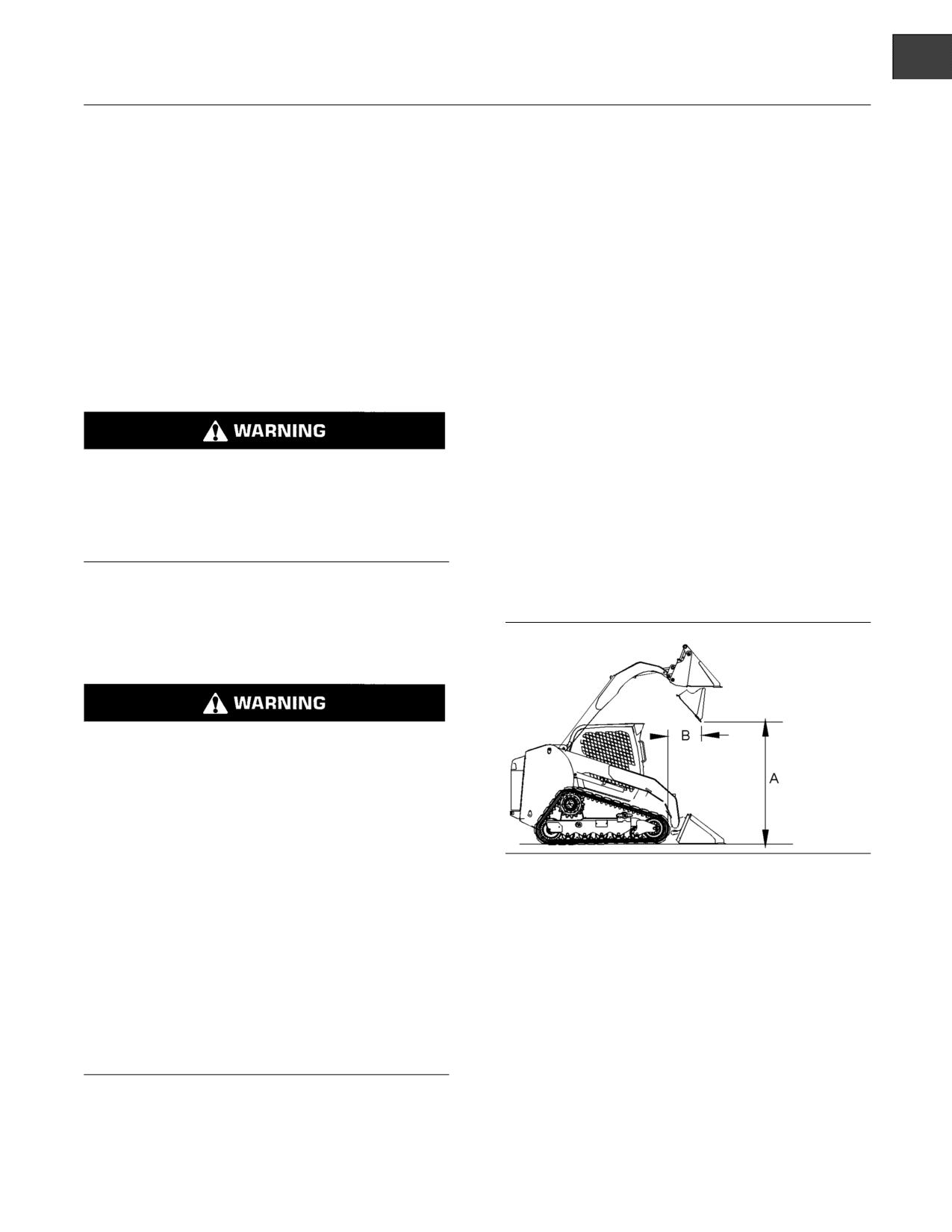
SEBU8407-06
39
Product Information Section
General Information
Product Information
• Full fuel tank
Section
• Caterpillar bucket
•
75 kg (165 lb) operator
General Information
Rated loads will vary with different attachments.
Consult your Caterpillar dealer regarding the rated
load for specific attachments.
i03710785
The rated operating load for Skid Steer Loaders that
Rated Load
are equipped with rubber tires is defined by the SAE
standard “J818:2007” and by the “EN 474-3:2006” as
SMCS Code: 6001; 6136; 6542; 7000
50% of the full static tipping load. The ground is hard
and the ground is level. The rated operating load
Bucket Rated Load
for machines that are equipped with steel tracks is
defined by the SAE standard “J818:2007” and by the
“EN 474-3:2006” as 35% of the full static tipping load.
The ground is soft and the ground is not level.
Failure to comply to the rated load can cause pos-
sible personal injury or property damage. Review
The corresponding dump clearance is given for each
the rated load of a particular work tool before per-
bucket at maximum lift height and at a 40 degree
forming any operation. Make adjustments to the
dump angle. The reach is given for each bucket
rated load as necessary for non-standard config-
at maximum lift height and at a 40 degree dump
urations.
angle. Clearance is measured from the ground to the
bucket edge in order to dump the load. The reach is
measured from the front of the track to the bucket
Note: Rated loads should be used as a guide.
edge.
Attachments, uneven ground conditions, soft ground
conditions, or poor ground conditions have effects on
rated loads. The operator is responsible for being
aware of these effects.
Machine stability is affected by many factors, in-
cluding the type of work tool and the position of a
work tool.
Machine stability and machine control can be sig-
nificantly affected if a work tool is not installed.
Operating a machine without a work tool can lead
to loss of control or tipping of the machine which
g01451258
Illustration 16
could result in serious injury or death.
Dimension (A) represents the dump clearance. Dimension (B)
represents the reach.
When you operate a machine without a work tool,
avoid the following conditions:
The following tables provide the Rated Operating
Capacity (ROC) for the standard machine
• excessive speed
configuration with a bucket.
• sharp turns
• abrupt implement movement
• slopes and uneven ground
Rated loads are based upon a standard machine with
the following conditions:
• Lubricants

40
SEBU8407-06
Product Information Section
General Information
Table 2
Dirt Buckets with Bolt on Edge
P/N
279-5441
285-6090
268-4083
Models
Weight
232 kg
511 lb
248 kg
546 lb
264 kg
582 lb
Bucket
1676 mm
66 in
1829 mm
72 in
1981 mm
78 in
R.O.C. 35%
1012 kg
2230 lb
1006 kg
2218 lb
1001 kg
2206 lb
279C
Dump Clearance
2397 mm
94 in
2397 mm
94 in
2397 mm
94 in
Reach
605 mm
24 in
605 mm
24 in
605 mm
24 in
R.O.C. 35%
1205 kg
2656 lb
1199 kg
2644 lb
1194 kg
2633 lb
289C
Dump Clearance
2507 mm
99 in
2507 mm
99 in
2507 mm
99 in
Reach
920 mm
36 in
920 mm
36 in
920 mm
36 in
R.O.C. 35%
1302 kg
2871 lb
1296 kg
2859 lb
1292 kg
2848 lb
299C
Dump Clearance
2554 mm
101 in
2554 mm
101 in
2554 mm
101 in
Reach
923 mm
36 in
923 mm
36 in
923 mm
36 in
Table 3
General Purpose Buckets
P/N
279-5368
279-5372
279-5376
292-9271
Weight
221 kg
487 lb
234 kg
516 lb
247 kg
544 lb
279 kg
614 lb
Models
2134
1829
1981
84 High
Bucket
1676 mm
66 in
72 in
78 in
mm High
mm
mm
Capacity
Capacity
R.O.C. 35%
1002 kg
2210 lb
998 kg
2201 lb
993 kg
2190 lb
962 kg
2122 lb
2391
2391
2330
279C
Dump Clearance
2391 mm
94 in
94 in
94 in
92 in
mm
mm
mm
Reach
633 mm
25 in
633 mm
25 in
633 mm
25 in
703 mm
28 in
R.O.C. 35%
1192 kg
2628 lb
1188 kg
2619 lb
1182 kg
2607 lb
1146 kg
2527 lb
2502
2502
2440
Dump Clearance
2502 mm
99 in
99 in
99 in
96 in
289C
mm
mm
mm
1018
Reach
948 mm
37 in
948 mm
37 in
948 mm
37 in
40 in
mm
R.O.C. 35%
1288 kg
2840 lb
1284 kg
2831 lb
1279 kg
2819 lb
1240 kg
2734 lb
2549
2549
2487
Dump Clearance
2549 mm
100 in
100 in
100 in
98 in
299C
mm
mm
mm
1021
Reach
951 mm
37 in
951 mm
37 in
951 mm
37 in
40 in
mm

SEBU8407-06
41
Product Information Section
General Information
Table 4
Multipurpose Buckets
P/N
279-5390
279-5398
279-5403
293-0139
Weight
355 kg
782 lb
374 kg
824 lb
393 kg
866 lb
393 kg
866 lb
Models
1676
1829
1981
2134
Bucket
66 in
72 in
78 in
84 in
mm
mm
mm
mm
R.O.C. 35%
946 kg
2086 lb
939 kg
2071 lb
938 kg
2068 lb
931 kg
2054 lb
2384
2384
2384
2384
279C
Dump Clearance
94 in
94 in
94 in
94 in
mm
mm
mm
mm
Reach
636 mm
25 in
636 mm
25 in
636 mm
25 in
636 mm
25 in
R.O.C. 35%
1132 kg
2496 lb
1125 kg
2481 lb
1125 kg
2480 lb
1119 kg
2467 lb
2495
2495
2495
2495
289C
Dump Clearance
98 in
98 in
98 in
98 in
mm
mm
mm
mm
Reach
951 mm
37 in
951 mm
37 in
951 mm
37 in
951 mm
37 in
R.O.C. 35%
1227 kg
2705 lb
1220 kg
2690 lb
1220 kg
2690 lb
1214 kg
2676 lb
2542
2542
2542
2542
299C
Dump Clearance
100 in
100 in
100 in
100 in
mm
mm
mm
mm
Reach
954 mm
38 in
954 mm
38 in
954 mm
38 in
954 mm
38 in
Table 5
Multipurpose Buckets with Bolt On Edge and Debris Guard
P/N
325-7050
325-7060
325-7070
325-7080
Weight
397 kg
876 lb
421 kg
928 lb
444 kg
979 lb
468 kg
1031 lb
Models
1981
2134
Bucket
1676 mm
66 in
1829 mm
72 in
78 in
84 in
mm
mm
R.O.C. 35%
918 kg
2024 lb
909 kg
2004 lb
905 kg
1995 lb
896 kg
1976 lb
2358
2358
279C
Dump Clearance
2358 mm
93 in
2358 mm
93 in
93 in
93 in
mm
mm
Reach
651 mm
26 in
651 mm
26 in
651 mm
26 in
651 mm
26 in
R.O.C. 35%
1100 kg
2426 lb
1091 kg
2406 lb
1088 kg
2399 lb
1080 kg
2381 lb
2469
2469
289C
Dump Clearance
2469 mm
97 in
2469 mm
97 in
97 in
97 in
mm
mm
Reach
965 mm
38 in
965 mm
38 in
965 mm
38 in
965 mm
38 in
R.O.C. 35%
1195 kg
2634 lb
1185 kg
2613 lb
1182 kg
2607 lb
1174 kg
2589 lb
2516
2516
299C
Dump Clearance
2516 mm
99 in
2516 mm
99 in
99 in
99 in
mm
mm
Reach
968 mm
38 in
968 mm
38 in
968 mm
38 in
968 mm
38 in

42
SEBU8407-06
Product Information Section
General Information
Table 6
Utility Buckets
P/N
285-6099
285-6102
Models
Weight
224 kg
494 lb
239 kg
526 lb
Bucket
1676 mm
66 in
1829 mm
72 in
R.O.C. 35%
1005 kg
2216 lb
1000 kg
2206 lb
279C
Dump Clearance
2366 mm
93 in
2366 mm
93 in
Reach
667 mm
26 in
667 mm
26 in
R.O.C. 35%
1195 kg
2636 lb
1190 kg
2625 lb
289C
Dump Clearance
2477 mm
98 in
2477 mm
98 in
Reach
982 mm
39 in
982 mm
39 in
R.O.C. 35%
1291 kg
2846 lb
1286 kg
2836 lb
299C
Dump Clearance
2524 mm
99 in
2524 mm
99 in
Reach
985 mm
39 in
985 mm
39 in
Table 7
Light Material Buckets
279-5429 (Bolt
296-7597 (Bolt
P/N
279-5421
279-5424
On Edge)
On Edge)
Models
Weight
266 kg
587 lb
280 kg
618 lb
338 kg
744 lb
368 kg
811 lb
1829
1981
2082
2438
Bucket
72 in
78 in
84 in
96 in
mm
mm
mm
mm
R.O.C. 35%
1046 kg
2307 lb
1041 kg
2294 lb
1006 kg
2219 lb
911 kg
2009 lb
2335
2335
2305
2305
279C
Dump Clearance
92 in
92 in
91 in
91 in
mm
mm
mm
mm
Reach
697 mm
27 in
697 mm
27 in
709 mm
28 in
709 mm
28 in
R.O.C. 35%
1251 kg
2757 lb
1245 kg
2745 lb
1208 kg
2663 lb
1090 kg
2404 lb
2445
2445
2415
2415
Dump Clearance
96 in
96 in
95 in
95 in
289C
mm
mm
mm
mm
1012
1012
1024
1024
Reach
40 in
40 in
40 in
40 in
mm
mm
mm
mm
R.O.C. 35%
1349 kg
2974 lb
1343 kg
2961 lb
1305 kg
2878 lb
1183 kg
2609 lb
2492
2492
2462
2462
Dump Clearance
98 in
98 in
97 in
97 in
299C
mm
mm
mm
mm
1015
1015
1027
1027
Reach
40 in
40 in
40 in
40 in
mm
mm
mm
mm
SEBU8407-06
43
Product Information Section
General Information
Table 8
Industrial Grapple Buckets(1)
P/N
157-7224
157-7225
217-6229
Models
Weight
425 kg
937 lb
440 kg
970 lb
459 kg
1012 lb
Bucket
1676 mm
66 in
1829 mm
72 in
1981 mm
78 in
R.O.C. 35%
985 kg
2172 lb
980 kg
2161 lb
974 kg
2147 lb
279C
Dump Clearance
2392 mm
94 in
2392 mm
94 in
2392 mm
94 in
Reach
636 mm
25 in
636 mm
25 in
636 mm
25 in
R.O.C. 35%
1187 kg
2617 lb
1182 kg
2606 lb
1176 kg
2592 lb
289C
Dump Clearance
2502 mm
99 in
2502 mm
99 in
2502 mm
99 in
Reach
951 mm
37 in
951 mm
37 in
951 mm
37 in
R.O.C. 35%
1286 kg
2835 lb
1280 kg
2823 lb
1274 kg
2809 lb
299C
Dump Clearance
2550 mm
100 in
2550 mm
100 in
2550 mm
100 in
Reach
954 mm
38 in
954 mm
38 in
954 mm
38 in
(1) The rated capacity is calculated with a full bucket of dirt. Grasping objects with the grapple will lower the rated capacity.
Table 9
Utility Grapple Buckets(1)
P/N
285-6111
285-6110
Models
Weight
363 kg
800 lb
379 kg
835 lb
Bucket
1676 mm
66 in
1829 mm
72 in
R.O.C. 35%
951 kg
2098 lb
946 kg
2085 lb
279C
Dump Clearance
2336 mm
92 in
2336 mm
92 in
Reach
678 mm
27 in
678 mm
27 in
R.O.C. 35%
1140 kg
2514 lb
1134 kg
2500 lb
289C
Dump Clearance
2446 mm
96 in
2446 mm
96 in
Reach
993 mm
39 in
993 mm
39 in
R.O.C. 35%
1235 kg
2724 lb
1230 kg
2711 lb
299C
Dump Clearance
2493 mm
98 in
2493 mm
98 in
Reach
996 mm
39 in
996 mm
39 in
(1) The rated capacity is calculated with a full bucket of dirt. Grasping objects with the grapple will lower the rated capacity.
Rated Loads for Forks
Note: Rated loads should be used as a guide.
Attachments, uneven ground conditions, soft ground
conditions, or poor ground conditions have effects on
rated loads. The operator is responsible for being
aware of these effects.
Failure to comply to the rated load can cause pos-
sible personal injury or property damage. Review
The rated operating load is defined by “SAE J1197”
the rated load of a particular work tool before per-
(October 2002) and “EN474”. The rated operating
forming any operation. Make adjustments to the
load is the least amount of weight of the following
rated load as necessary for non-standard config-
conditions:
urations.
•
35% of the full static tipping load on a surface that
is soft or a surface that is not level
•
50% of the full static tipping load on a surface that
is hard and level
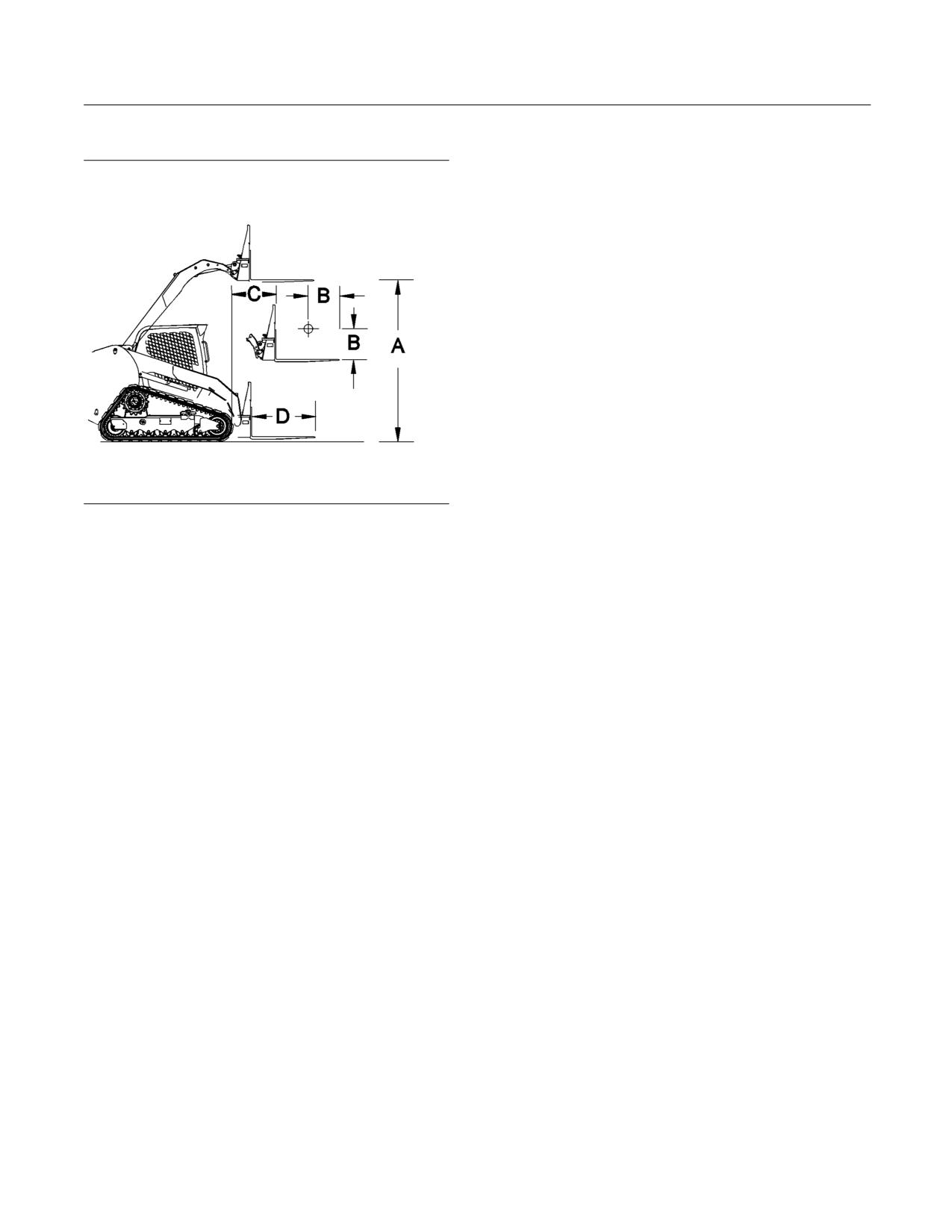
44
SEBU8407-06
Product Information Section
General Information
• The hydraulic lifting capacity
g01451260
Illustration 17
Dimension (A) represents the maximum fork height. Dimension (B)
represents the load center. Dimension (C) represents the reach.
Dimension (D) represents the fork tine length.
The maximum fork height (ground to top face of
fork) is given for a pallet fork that is horizontal at
maximum lift height. The reach (front of the tracks to
the front face of the fork) is given for a pallet fork that
is horizontal maximum reach.
The following tables provide the Rated Operating
Capacity (ROC) for the standard machine
configuration that is equipped with the following
items:
• Full fuel tank
• Lubricants
• 75 kg (165 lb) operator
• Caterpillar fork
SEBU8407-06
45
Product Information Section
General Information
Table 10
Pallet Fork
P/N
293-9427
293-9428
293-9429
Weight
182 kg
401 lb
192 kg
423 lb
201 kg
444 lb
Models
Fork
914 mm
36 in
1067 mm
42 in
1219 mm
48 in
Load Center
455 mm
18 in
535 mm
21 in
610 mm
24 in
R.O.C. 35%
863 kg
1902 lb
811 kg
1787 lb
768 kg
1692 lb
279C
Max Height of Fork
3025 mm
119 in
3025 mm
119 in
3025 mm
119 in
Reach
849 mm
33 in
849 mm
33 in
849 mm
33 in
R.O.C. 35%
1012 kg
2231 lb
948 kg
2091 lb
896 kg
1976 lb
289C
Max Height of Fork
3130 mm
123 in
3130 mm
123 in
3130 mm
123 in
Reach
743 mm
29 in
743 mm
29 in
743 mm
29 in
R.O.C. 35%
1093 kg
2411 lb
1026 kg
2263 lb
971 kg
2141 lb
299C
Max Height of Fork
3177 mm
125 in
3177 mm
125 in
3177 mm
125 in
Reach
730 mm
29 in
730 mm
29 in
730 mm
29 in
Table 11
Utility Fork
P/N
285-6105
285-6110
Weight
198 kg
436 lb
219 kg
484 lb
Models
Fork
1676 mm
66 in
1829 mm
72 in
Load Center
314 mm
12 in
314 mm
12 in
279C
R.O.C. 35%
986 kg
2174 lb
980 kg
2162 lb
289C
R.O.C. 35%
1168 kg
2575 lb
1162 kg
2562 lb
299C
R.O.C. 35%
1259 kg
2776 lb
1253 kg
2764 lb
Table 12
Utility Grapple Fork
P/N
285-6114
285-6115
Weight
304 kg
671 lb
326 kg
718 lb
Models
Fork
1676 mm
66 in
1829 mm
72 in
Load Center
314 mm
12 in
314 mm
12 in
279C
R.O.C. 35%
988 kg
2179 lb
981 kg
2164 lb
289C
R.O.C. 35%
1179 kg
2600 lb
1172 kg
2585 lb
299C
R.O.C. 35%
1273 kg
2806 lb
1266 kg
2791 lb
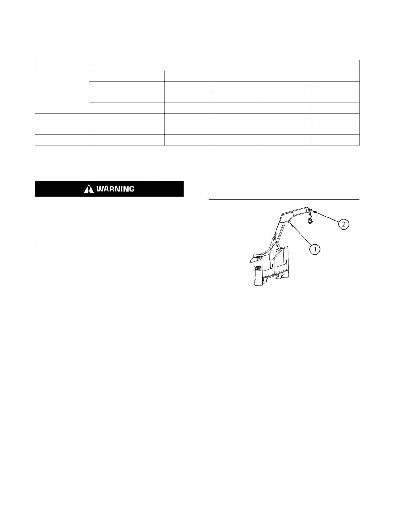
46
SEBU8407-06
Product Information Section
General Information
Table 13
Industrial Grapple Fork
P/N
279-5350
279-5360
Weight
502 kg
1106 lb
548 kg
1208 lb
Models
Fork
1676 mm
66 in
1829 mm
72 in
Load Center
280 mm
11 in
280 mm
11 in
279C
R.O.C. 35%
940 kg
2072 lb
925 kg
2041 lb
289C
R.O.C. 35%
1134 kg
2501 lb
1121 kg
2471 lb
R.O.C. 35%
1229 kg
2709 lb
1215 kg
2679 lb
Rated Load with a Material Handling
• Lubricants
Arm
•
75 kg (165 lb) operator
• Caterpillar Material Handling Arm
Failure to comply to the rated load can cause pos-
sible personal injury or property damage. Review
the rated load of a particular work tool before per-
forming any operation. Make adjustments to the
rated load as necessary for non-standard config-
urations.
Note: Rated loads should be used as a guide.
Attachments, uneven ground conditions, soft ground
conditions, or poor ground conditions have effects on
rated loads. The operator is responsible for being
aware of these effects.
The maximum placement height (ground line to the
g00668844
Illustration 18
chain hook) is given for the highest position of the
Lifting point 1 (1)
material handling arm. The maximum reach (front
of the machine to the chain hook) is the maximum
Lifting point 2 (2)
horizontal reach of the material handling arm.
The rated operating capacity is the least amount of
weight of the following conditions:
•
35% of the full static tipping load on a surface that
is soft or a surface that is uneven
•
50% of the full static tipping load on a surface that
is hard and level
• The hydraulic lifting capacity
• The material handling arm has a structural capacity
of 907 kg (2000 lb).
The following tables provide the Rated Operating
Capacity (ROC) for the standard machine
configuration that is equipped with the following
items:
• Full fuel tank
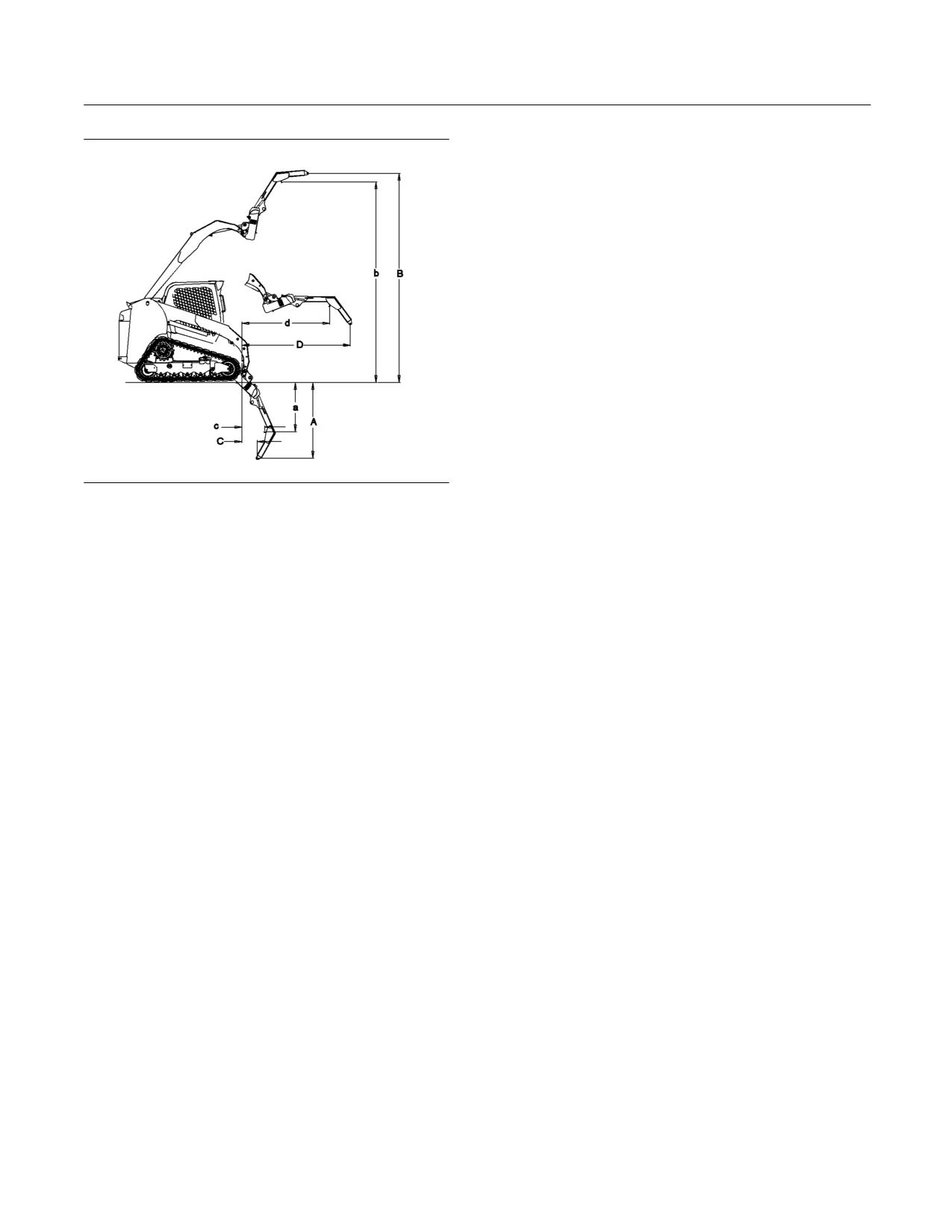
SEBU8407-06
47
Product Information Section
General Information
g01451261
Illustration 19
Dimension (A) represents the clearance at the full down position
from Lifting Point 2. Dimension (a) represents the clearance at the
full down position from Lifting Point 1. Dimension (B) represents the
clearance at maximum height from Lifting Point 2. Dimension (b)
represents the clearance at maximum height from Lifting Point 1.
Dimension (C) represents the minimum reach from Lifting Point 2.
Dimension (c) represents the minimum reach from Lifting Point 1.
Dimension (D) represents the maximum reach from Lifting Point 2.
Dimension (d) represents the maximum reach from Lifting Point 1.
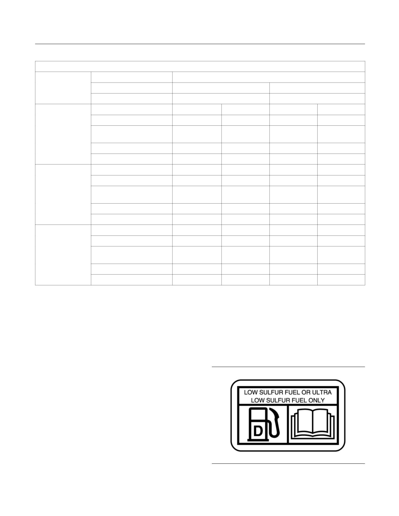
48
SEBU8407-06
Product Information Section
General Information
Table 14
Material Handling Arm
P/N
216-8756
Models
Weight
131 kg
289 lb
Point 1
Point 2
R.O.C. 35%
651 kg
1435 lb
542 kg
1195 lb
Clearance at Full Down
-974 mm
-38 in
-1459 mm
-57 in
Clearance at Maximum
279C
4359 mm
172 in
4804 mm
189 in
Height
Minimum Reach
437 mm
17 in
285 mm
11 in
Maximum Reach
1756 mm
69 in
2201 mm
87 in
R.O.C. 35%
757 kg
1669 lb
625 kg
1378 lb
Clearance at Full Down
-947 mm
-37 in
-1441 mm
-57 in
Clearance at Maximum
289C
4470 mm
176 in
4915 mm
194 in
Height
Minimum Reach
516 mm
20 in
398 mm
16 in
Maximum Reach
1650 mm
65 in
2096 mm
83 in
R.O.C. 35%
862 kg
1901 lb
710 kg
1566 lb
Clearance at Full Down
-947 mm
-37 in
-1441 mm
-57 in
Clearance at Maximum
299C
4517 mm
178 in
4962 mm
195 in
Height
Minimum Reach
516 mm
20 in
398 mm
16 in
Maximum Reach
1637 mm
64 in
2083 mm
82 in
i03710844
The maximum fore and aft slope for proper lubrication
is 25 degrees continuous and 35 degrees intermittent.
Specifications
Intermittent time is 2 minutes.
SMCS Code: 7000
Use this machine in environments with no explosive
gases.
Intended Use
Diesel Fuel Requirements
This machine is classified as a Skid Steer Loader with
wheels or tracks as described in “EN ISO 6165:2006”.
This machine normally has a front mounted bucket or
another work tool for digging, loading, lifting, carrying
and moving material such as earth, crushed rock or
gravel. Additional work tools allow this machine to
perform other specific tasks.
Application/Configuration
Restrictions
Refer to Operation and Maintenance Manual,
“Machine Data” below for information about
maximum machine weight.
g01416469
Illustration 20
Refer to Operation and Maintenance Manual,
“Approved Work Tools” for information about
acceptable work tools.
SEBU8407-06
49
Product Information Section
General Information
In the United States, 0.0015 percent (15 ppm) sulfur
diesel fuels have been used in most on-highway
truck engines since 15 October 2006. This ultra
Mixing alcohol or gasoline with diesel fuel can pro-
low sulfur diesel fuel (ULSD) was mandated as a
duce an explosive mixture in the engine crankcase
means of directly reducing particulate emissions from
or fuel tank.
on-highway diesel engines. This ultra low sulfur fuel
will also be used in Caterpillar commercial diesel
Personal injury and damage to the engine may
engines and in Caterpillar machine engines. ULSD
result. Caterpillar recommends against this prac-
fuel will be used when low emissions are required.
tice.
Note: In Europe, ultra low sulfur diesel fuel will have
a maximum of 0.0010 percent (10 ppm) sulfur and is
There are many different types of fuel additives that
typically referred to as “sulfur-free”.
are available to use. Caterpillar does not generally
recommend the use of fuel additives.
NOTICE
Refer to Operation and Maintenance Manual,
Heavy Fuel Oil (HFO), Residual fuel, or Blended fuel
SEBU6251, “Caterpillar Commercial Diesel Engine
must NOT be used in Caterpillar diesel engines (ex-
Fluids Recommendations” for the use of fuel additives
cept in 3600 Series HFO engines). Blended fuel is
and fuel conditioners.
residual fuel that has been diluted with a lighter fuel
(cutter stock) so that they will flow. Blended fuels are
also referred to as heavy fuel oils. Severe component
Machine Data
wear and component failures will result if HFO type
fuels are used in engines that are configured to use
The specifications that are given herein describe
distillate fuel.
the machine as the machine is manufactured by
Caterpillar Inc. The machine is full of fluids. The
machine is equipped with all options. The weight
Low Sulfur Diesel (LSD) fuel will have ≤500 ppm
does not include the operator, work tools, or other
(0.05%) sulfur. Ultra Low Sulfur Diesel (ULSD)
attachments.
fuel will have ≤15 ppm (0.0015%) sulfur using the
“ASTM D5453”, “ASTM D2622”, or “ISO 20846, ISO
20884” test methods. Certain applications and/or
governments/localities MAY require the use of ULSD
fuel. Emission controlled diesel engines and/or
diesel engines equipped with exhaust aftertreatment
devices MAY require the use of ULSD fuel. Diesel
engines equipped with a Diesel Particulate Filter
(DPF) require the use of ULSD. Consult federal,
state, and local authorities for guidance on fuel
requirements for your area. Also, consult the specific
engine Operation and Maintenance Manual for
guidance.
There are many other diesel fuel specifications that
are published by governments and by technological
societies. Usually, those specifications do not review
all the requirements that are addressed in the
Operation and Maintenance Manual, SEBU6251,
“Caterpillar Commercial Diesel Engine Fluids
Recommendations”in the section “Caterpillar
Specification for Distillate Diesel Fuel”. To ensure
optimum engine performance, a complete fuel
analysis should be obtained before engine operation.
50
SEBU8407-06
Product Information Section
General Information
Table 15
279C
289C
299C
Maximum
Machine
4533 kg (9994 lb)
4752 kg (10476 lb)
4871 kg (10739 lb)
Weight
Overall
2951 mm (116 inch)
2951 mm (116 inch)
3092 mm (122 inch)
Length
Height
2083 mm (82 inch)
2083 mm (82 inch)
2083 mm (82 inch)
Width
1981 mm (78 inch)
1981 mm (78 inch)
1981 mm (78 inch)
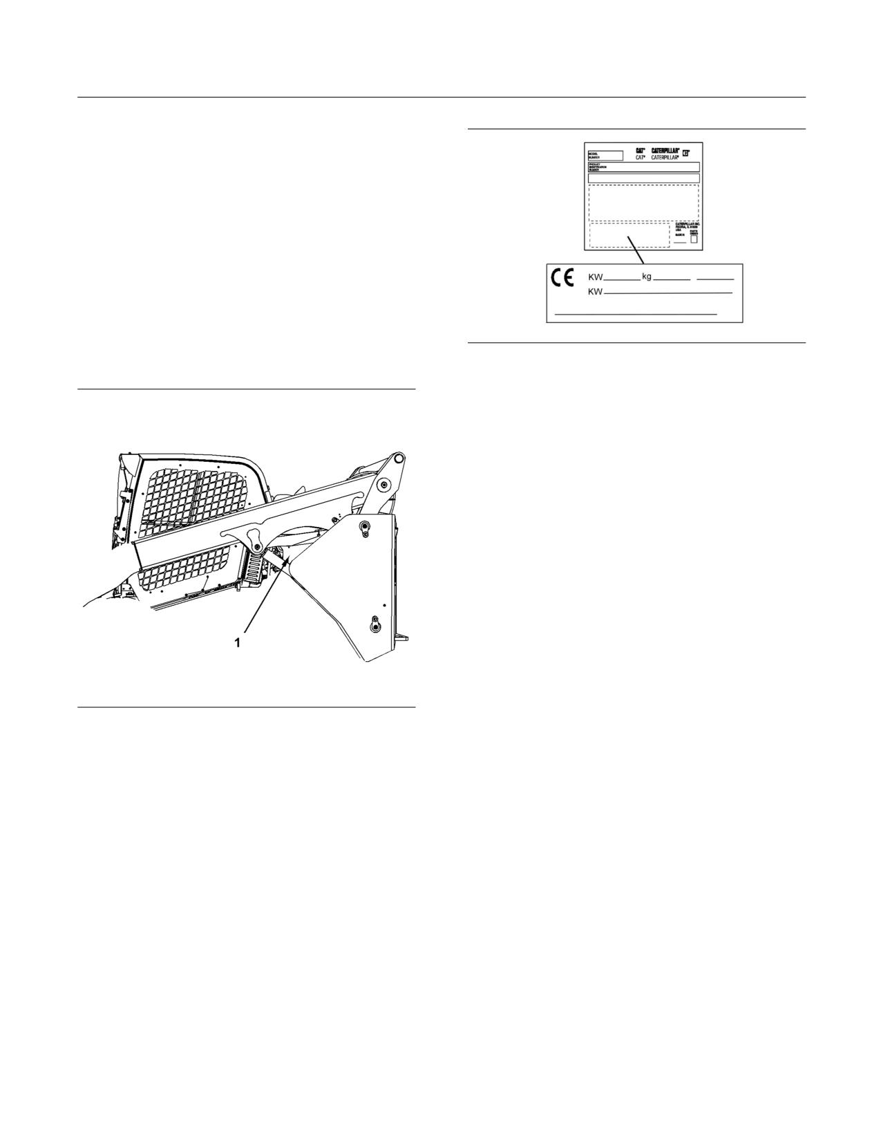
SEBU8407-06
51
Product Information Section
Identification Information
Identification Information
i04415225
Plate Locations and Film
Locations
SMCS Code: 1000; 7000
The Product Identification Number (PIN) will be used
to identify a powered machine that is designed for
an operator to ride.
For quick reference, record the identification numbers
g02020534
Illustration 22
in the spaces that are provided below the illustration.
This plate is located on the bottom left side of the
Identification Plate.
Note: The CE plate is on machines that are certified
to the European Union requirements that are listed
on the “Document of Conformity”. If the machine is
equipped with the plate for the European Union, the
plate is attached to the PIN plates.
For machines that are compliant to “2006/42/EC”, the
following information is stamped onto the CE plate.
For quick reference, record this information in the
spaces that are provided below.
• Year of Manufacture
____________________________________
• Engine Power for primary engine (kW)
_____________
• Engine Power for additional engine (if equipped)
_______________________________________________________________
g02639378
Illustration 21
• Typical machine operating weight for European
The Identification Plate for the machine is located under the lift
market (kg)
_______________________________________________
arm on the left side.
• Year of construction
____________________________________
(1) Machine PIN
____________________________________________
• Machine Function
_______________________________________
Year of Manufacture
_______________________________________
For machines that are compliant with “98/37/EC” the
• PIN
_________________________________________________________
following information is stamped on the CE plate. For
quick reference, record this information in the spaces
• Model
______________________________________________________
that are provided below.
• Power (kW)
_______________________________________________
• Engine Power for primary engine (kW)
_____________
• Weight (kg)
_______________________________________________
• Typical machine operating weight for European
market (kg)
_______________________________________________
The engine serial number plate is located on the
engine.
• Year
________________________________________________________
• Engine Serial Number
_________________________________
For the name of the manufacturer, the address of
the manufacturer, and the country of origin, refer to
the PIN plate.
52
SEBU8407-06
Product Information Section
Identification Information
i04687649
Emissions Certification Film
SMCS Code: 1000; 7000; 7405
Certification Label for Emissions
Note: This information is pertinent in the United
States, in Canada, and in Europe.
Consult your Cat dealer for an Emission Control
Warranty Statement.
This label is located on the engine valve cover.
SEBU8407-06
53
Product Information Section
Identification Information
i03659202
Declaration of Conformity
SMCS Code: 1000; 7000
Table 16
An EC Declaration of Conformity document was provided with the machine if it was manufactured to comply with specific
requirements for the European Union. In order to determine the details of the applicable Directives, review the complete
EC Declaration of Conformity provided with the machine. The extract shown below from an EC Declaration of Conformity
for machines that are declared compliant to “2006/42/EC” applies only to those machines originally “CE” marked by the
manufacturer listed and which have not since been modified.
EC DECLARATION OF CONFORMITY OF MACHINERY
Manufacturer: Caterpillar Inc., 100 N.E. Adams Street, Peoria, Illinois 61629, USA
Person authorized to compile the Technical File and to communicate relevant part (s) of the Technical File to the
Authorities of European Union Member States on request:
Standards & Regulations Manager, Caterpillar France S.A.S 40,
Avenue Leon-Blum, B.P. 55, 38041 Grenoble Cedex 9, France
I, the undersigned,
_________, hereby certify that the construction equipment specified hereunder
Description:
Generic Denomination:
Earth moving Equipment
Function:
Compact Track loader
Model/Type:
(279C), (289C), 299C Compact Track Loader
Serial Number:
Commercial Name:
Caterpillar
Fulfils all the relevant provisions of the following Directives
Directives
Notified Body
Document No.
2006/42/EC
N/A
2000/14/EC amended by 2005/88/EC,
Note (1)
2004/108/EC
N/A
Note (1) Annex -_____
Guaranteed Sound Power Level -____
dB (A)
Representative Equipment Type Sound Power Level -
____dB (A)
Engine Power per
____-
____
kW Rated engine speed -
____
rpm
Technical Documentation accessible through person listed above authorized to compile the Technical File
Done at:
Signature
Date:
Name/Position
Note: The above information was correct as of September 2009, but may be subject to change, please refer to the individual
declaration of conformity issued with the machine for exact details.
54
SEBU8407-06
Product Information Section
Identification Information
i03740705
Declaration of Conformity
SMCS Code: 1000; 7000
Table 17
An EC Declaration of Conformity document was provided with the machine if it was manufactured to comply with specific
requirements for the European Union. In order to determine the details of the applicable Directives, review the complete
EC Declaration of Conformity provided with the machine. The extract shown below from an EC Declaration of Conformity
for machines that are declared compliant to “2006/42/EC” applies only to those machines originally “CE” marked by the
manufacturer listed and which have not since been modified.
EC DECLARATION OF CONFORMITY OF MACHINERY
Manufacturer:
Caterpillar Inc., 100 N.E. Adams Street, Peoria, Illinois 61629, USA
Person authorized to compile the Technical File and to communicate relevant part (s) of the Technical File to the
Authorities of European Union Member States on request:
Standards & Regulations Manager, Caterpillar France S.A.S 40,
Avenue Leon-Blum, B.P. 55, 38041 Grenoble Cedex 9, France
I, the undersigned,
_________, hereby certify that the construction equipment specified hereunder
Description:
Generic Denomination:
Earth-moving Equipment
Function:
Rake with Top Clamp
Model/Type:
Industrial Grapple Rake
Serial Number:
Commercial Name:
Caterpillar
Fulfils all the relevant provisions of the following Directives
Directives
Notified Body
Document No.
2006/42/EC
N/A
Note (1) Technical Documentation accessible through person listed above authorized to compile the Technical File
Done at:
Signature
Date:
Name/Position
Note: The above information was correct as of October 2009, but may be subject to change, please refer to the individual
declaration of conformity issued with the machine for exact details.
SEBU8407-06
55
Product Information Section
Identification Information
i03740703
Declaration of Conformity
SMCS Code: 1000; 7000
Table 18
An EC Declaration of Conformity document was provided with the machine if it was manufactured to comply with specific
requirements for the European Union. In order to determine the details of the applicable Directives, review the complete
EC Declaration of Conformity provided with the machine. The extract shown below from an EC Declaration of Conformity
for machines that are declared compliant to “2006/42/EC” applies only to those machines originally “CE” marked by the
manufacturer listed and which have not since been modified.
EC DECLARATION OF CONFORMITY OF MACHINERY
Manufacturer:
Caterpillar Inc., 100 N.E. Adams Street, Peoria, Illinois 61629, USA
Person authorized to compile the Technical File and to communicate relevant part (s) of the Technical File to the
Authorities of European Union Member States on request:
Standards & Regulations Manager, Caterpillar France S.A.S 40,
Avenue Leon-Blum, B.P. 55, 38041 Grenoble Cedex 9, France
I, the undersigned,
_________, hereby certify that the construction equipment specified hereunder
Description:
Generic Denomination:
Earth-moving Equipment
Function:
Bucket with Top Clamp
Model/Type:
Industrial Gapple Bucket, Utility Grapple Bucket
Serial Number:
Commercial Name:
Caterpillar
Fulfils all the relevant provisions of the following Directives
Directives
Notified Body
Document No.
2006/42/EC
N/A
Note (1) Technical Documentation accessible through person listed above authorized to compile the Technical File
Done at:
Signature
Date:
Name/Position
Note: The above information was correct as of October 2009, but may be subject to change, please refer to the individual
declaration of conformity issued with the machine for exact details.
56
SEBU8407-06
Product Information Section
Identification Information
i03740584
Declaration of Conformity
SMCS Code: 1000; 7000
Table 19
An EC Declaration of Conformity document was provided with the machine if it was manufactured to comply with specific
requirements for the European Union. In order to determine the details of the applicable Directives, review the complete
EC Declaration of Conformity provided with the machine. The extract shown below from an EC Declaration of Conformity
for machines that are declared compliant to “2006/42/EC” applies only to those machines originally “CE” marked by the
manufacturer listed and which have not since been modified.
EC DECLARATION OF CONFORMITY OF MACHINERY
Manufacturer:
Caterpillar Inc., 100 N.E. Adams Street, Peoria, Illinois 61629, USA
Person authorized to compile the Technical File and to communicate relevant part (s) of the Technical File to the
Authorities of European Union Member States on request:
Standards & Regulations Manager, Caterpillar France S.A.S 40,
Avenue Leon-Blum, B.P. 55, 38041 Grenoble Cedex 9, France
I, the undersigned,
_________, hereby certify that the construction equipment specified hereunder
Description:
Generic Denomination:
Earth-moving Equipment
Function:
Fork with Top Clamp
Model/Type:
Industrial Grapple Fork, Utility Grapple Fork
Serial Number:
Commercial Name:
Caterpillar
Fulfils all the relevant provisions of the following Directives
Directives
Notified Body
Document No.
2006/42/EC
N/A
Note (1) Technical Documentation accessible through person listed above authorized to compile the Technical File
Done at:
Signature
Date:
Name/Position
Note: The above information was correct as of October 2009, but may be subject to change, please refer to the individual
declaration of conformity issued with the machine for exact details.
SEBU8407-06
57
Product Information Section
Identification Information
i03740663
Declaration of Conformity
SMCS Code: 1000; 7000
Table 20
An EC Declaration of Conformity document was provided with the machine if it was manufactured to comply with specific
requirements for the European Union. In order to determine the details of the applicable Directives, review the complete
EC Declaration of Conformity provided with the machine. The extract shown below from an EC Declaration of Conformity
for machines that are declared compliant to “2006/42/EC” applies only to those machines originally “CE” marked by the
manufacturer listed and which have not since been modified.
EC DECLARATION OF CONFORMITY OF MACHINERY
Manufacturer:
Caterpillar Inc., 100 N.E. Adams Street, Peoria, Illinois 61629, USA
Person authorized to compile the Technical File and to communicate relevant part (s) of the Technical File to the
Authorities of European Union Member States on request:
Standards & Regulations Manager, Caterpillar France S.A.S 40,
Avenue Leon-Blum, B.P. 55, 38041 Grenoble Cedex 9, France
I, the undersigned,
_________, hereby certify that the construction equipment specified hereunder
Description:
Generic Denomination:
Earth-moving Equipment
Function:
Multipurpose Bucket
Model/Type:
Multipurpose (MP) Bucket
Serial Number:
Commercial Name:
Caterpillar
Fulfils all the relevant provisions of the following Directives
Directives
Notified Body
Document No.
2006/42/EC
N/A
Note (1) Technical Documentation accessible through person listed above authorized to compile the Technical File
Done at:
Signature
Date:
Name/Position
Note: The above information was correct as of October 2009, but may be subject to change, please refer to the individual
declaration of conformity issued with the machine for exact details.
58
SEBU8407-06
Product Information Section
Identification Information
i03740701
Declaration of Conformity
SMCS Code: 1000; 7000
Table 21
An EC Declaration of Conformity document was provided with the machine if it was manufactured to comply with specific
requirements for the European Union. In order to determine the details of the applicable Directives, review the complete
EC Declaration of Conformity provided with the machine. The extract shown below from an EC Declaration of Conformity
for machines that are declared compliant to “2006/42/EC” applies only to those machines originally “CE” marked by the
manufacturer listed and which have not since been modified.
EC DECLARATION OF CONFORMITY OF MACHINERY
Manufacturer:
Caterpillar Inc., 100 N.E. Adams Street, Peoria, Illinois 61629, USA
Person authorized to compile the Technical File and to communicate relevant part (s) of the Technical File to the
Authorities of European Union Member States on request:
Standards & Regulations Manager, Caterpillar France S.A.S 40,
Avenue Leon-Blum, B.P. 55, 38041 Grenoble Cedex 9, France
I, the undersigned,
_________, hereby certify that the construction equipment specified hereunder
Description:
Generic Denomination:
Earth-moving Equipment
Function:
Material Handling Arm
Model/Type:
Material Handling Arm (MHA), Truss Boom, Lifting
Hook
Serial Number:
Commercial Name:
Caterpillar
Fulfils all the relevant provisions of the following Directives
Directives
Notified Body
Document No.
2006/42/EC
N/A
Note (1) Technical Documentation accessible through person listed above authorized to compile the Technical File
Done at:
Signature
Date:
Name/Position
Note: The above information was correct as of October 2009, but may be subject to change, please refer to the individual
declaration of conformity issued with the machine for exact details.
SEBU8407-06
59
Operation Section
Before Operation
i03921321
Operation Section
Daily Inspection
SMCS Code: 1000; 7000
Before Operation
NOTICE
i02601969
Accumulated grease and oil on a machine is a fire haz-
ard. Remove this debris with steam cleaning or high
Mounting and Dismounting
pressure water, at least every 1000 hours or each time
any significant quantity of oil is spilled on a machine.
SMCS Code: 7000
For maximum service life of the machine, make
a thorough daily inspection before you operate
the machine. Remove any debris from the engine
compartment and the undercarriage. Ensure that
all guards, covers, and caps are secured. Inspect
all hoses and belts for damage. Make the needed
repairs before you operate the machine.
Inspect the area around the machine and under the
machine. Look for loose bolts, trash buildup, oil,
coolant, fuel, or exhaust leakage, broken parts, or
worn parts.
Note: Watch closely for leaks. If you observe a leak,
g00037860
Illustration 23
find the source of the leak and correct the leak. If you
Typical example
suspect a leak or you observe a leak, check the fluid
levels more frequently.
Mount the machine and dismount the machine only
at locations that have steps and/or handholds. Before
Inspect the condition of the equipment and of the
you mount the machine, clean the steps and the
hydraulic components.
handholds. Inspect the steps and handholds. Make
all necessary repairs.
Check all of the oil levels, all of the coolant levels,
and all of the fuel levels.
Face the machine whenever you get on the machine
and whenever you get off the machine.
Remove any trash buildup and debris. Inspect the
area between lift cylinder and lower plate of the lift
Maintain a three-point contact with the steps and with
tower for debris and clean as necessary. Inspect the
the handholds.
rear portion of the right side lift cylinder tower for
debris and clean as necessary.
Note: Three-point contact can be two feet and one
hand. Three-point contact can also be one foot and
Perform all necessary repairs before you operate the
two hands.
machine.
Do not mount a moving machine. Do not dismount a
Ensure that all covers and guards are securely
moving machine. Never jump off the machine. Do
attached.
not carry tools or supplies when you try to mount the
machine or when you try to dismount the machine.
Adjust the mirrors for the correct rear view of the
Use a hand line to pull equipment onto the platform.
machine.
Do not use any controls as handholds when you
enter the operator compartment or when you exit the
Grease all of the fittings that are scheduled on a daily
operator compartment.
basis.
Daily, perform the procedures that are applicable
to your machine. Refer to the Operation and
Maintenance Manual, “Maintenance Interval
Schedule” “Every 10 Service Hours or Daily” category
for the list of procedures.
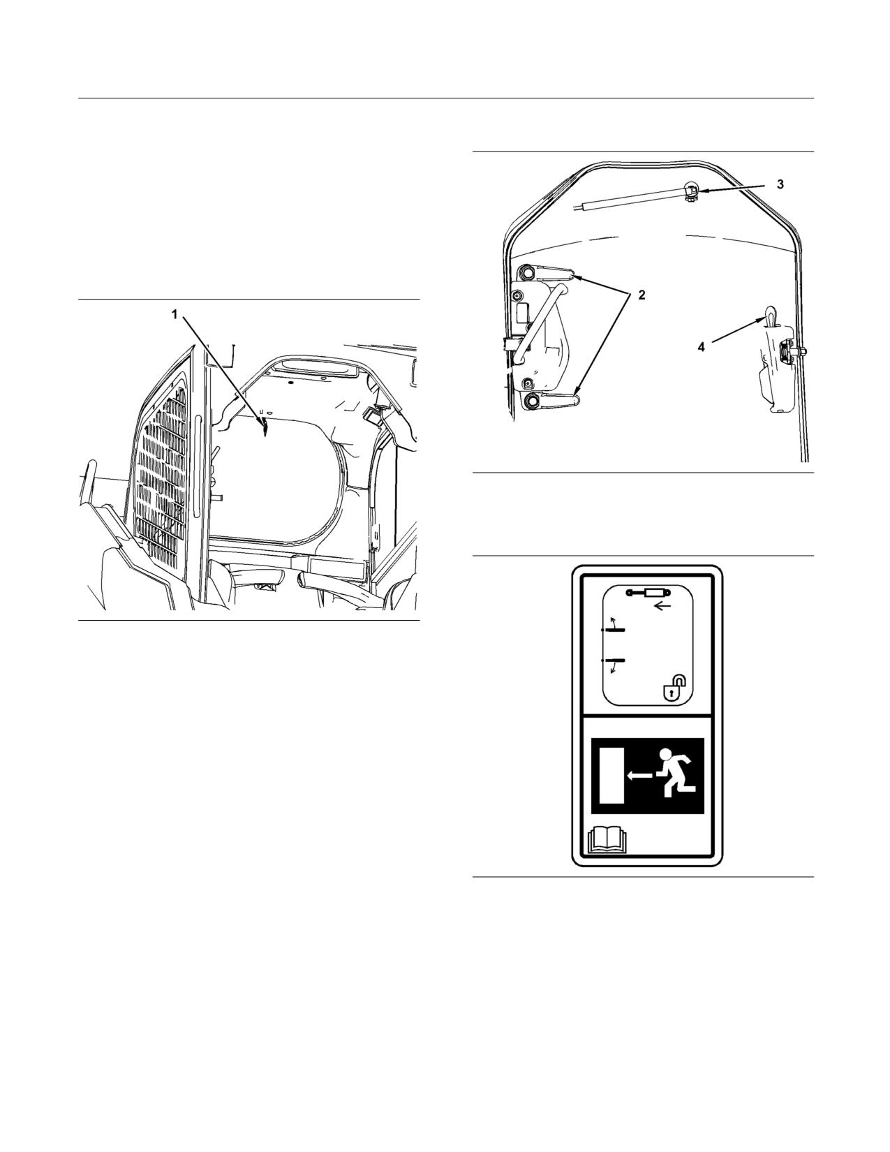
60
SEBU8407-06
Operation Section
Machine Operation
Secondary Exit
Machine Operation
i02518644
Alternate Exit
SMCS Code: 7000
Primary Exit
g01260322
Illustration 25
(2) Release levers for the hinge
(3) Quick release for the strut
(4) Door Latch
g01260321
Illustration 24
(1) Latch pin
The rear window in the machine serves as the
primary alternate exit. The window will need to be
removed in order to use the primary alternate exit.
Pull on the ring at the top of the window in order to
remove the window. This will remove the seal that
holds the window in place. When the seal is taken
out, carefully remove the window.
g01260324
Illustration 26
If necessary, the cab door may be removed from
the hinges from the inside of the machine. Use the
following procedure:
1. Release the door from the striker (4).
2. Use the two levers (2) in order to release the
hinge. Move the upper lever counterclockwise.
Move the lower lever clockwise.
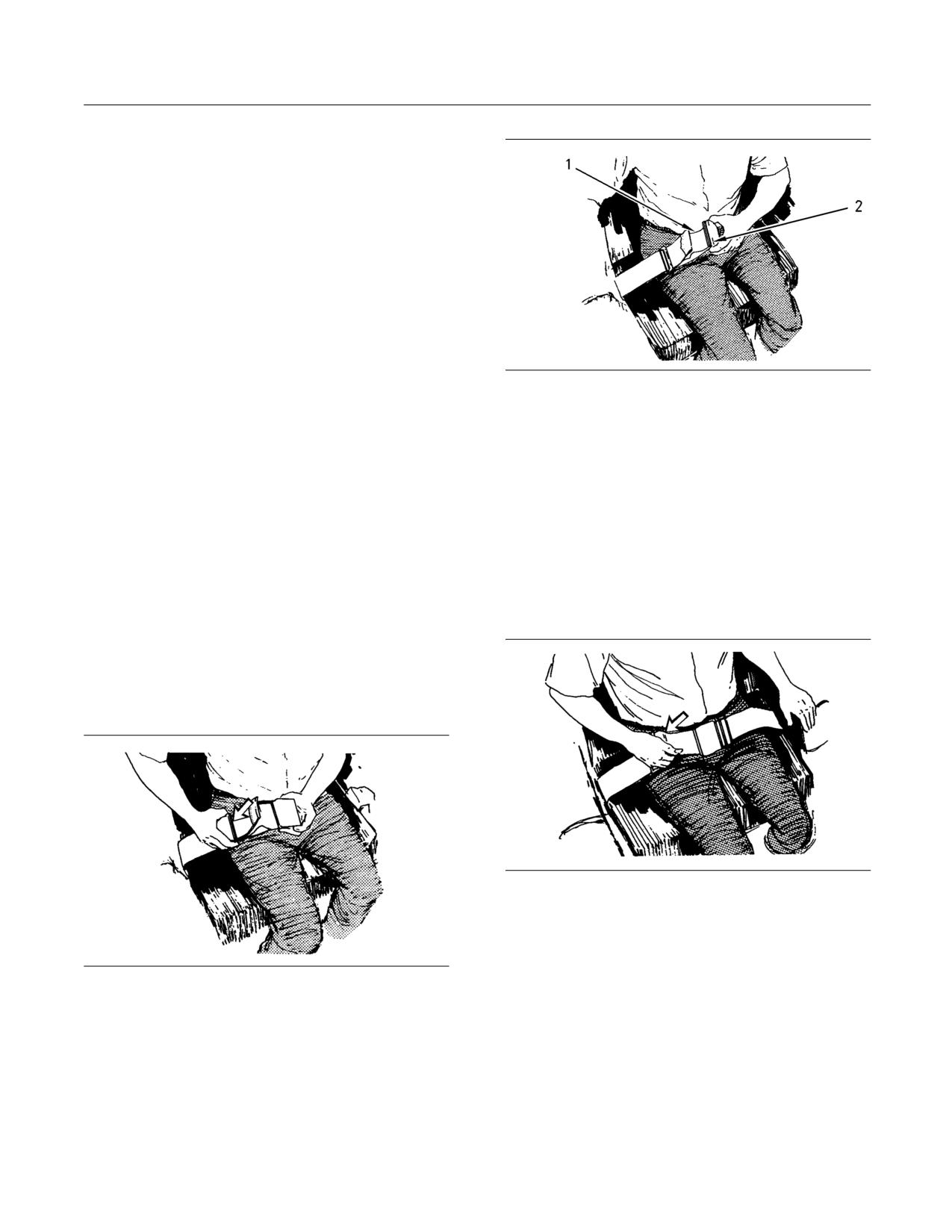
SEBU8407-06
61
Operation Section
Machine Operation
3. Locate the quick release (3) on the end of the
support strut. Move the quick release to the left
and hold the quick release.
4. Push up on the strut in order to release the strut
from the mount.
5. Push the door away from the cab.
i04200349
Seat Belt
SMCS Code: 7327
g00932817
Illustration 28
Note: This machine was equipped with a seat belt
when the machine was shipped from Caterpillar.
2. To remove the slack in outer loop (1), rotate buckle
At the time of installation, the seat belt and the
(2). This will free the lock bar. This permits the
instructions for installation of the seat belt meet the
seat belt to move through the buckle.
SAE J386 and ISO 6683 standards. Consult your Cat
dealer for all replacement parts.
3. Remove the slack from the outer belt loop by
pulling on the buckle.
Always check the condition of the seat belt and
the condition of the mounting hardware before you
4. Loosen the other half of the seat belt in the same
operate the machine.
manner. If the seat belt does not fit snugly with the
buckle in the center, readjust the seat belt.
Seat Belt Adjustment for
Shortening the Seat Belt
Non-Retractable Seat Belts
Adjust both ends of the seat belt. The seat belt should
be snug but comfortable.
Lengthening the Seat Belt
g00100713
Illustration 29
1. Fasten the seat belt. Pull out on the outer belt loop
in order to tighten the seat belt.
2. Adjust the other half of the seat belt in the same
g00100709
Illustration 27
manner.
1. Unfasten the seat belt.
3. If the seat belt does not fit snugly with the buckle
in the center, readjust the seat belt.
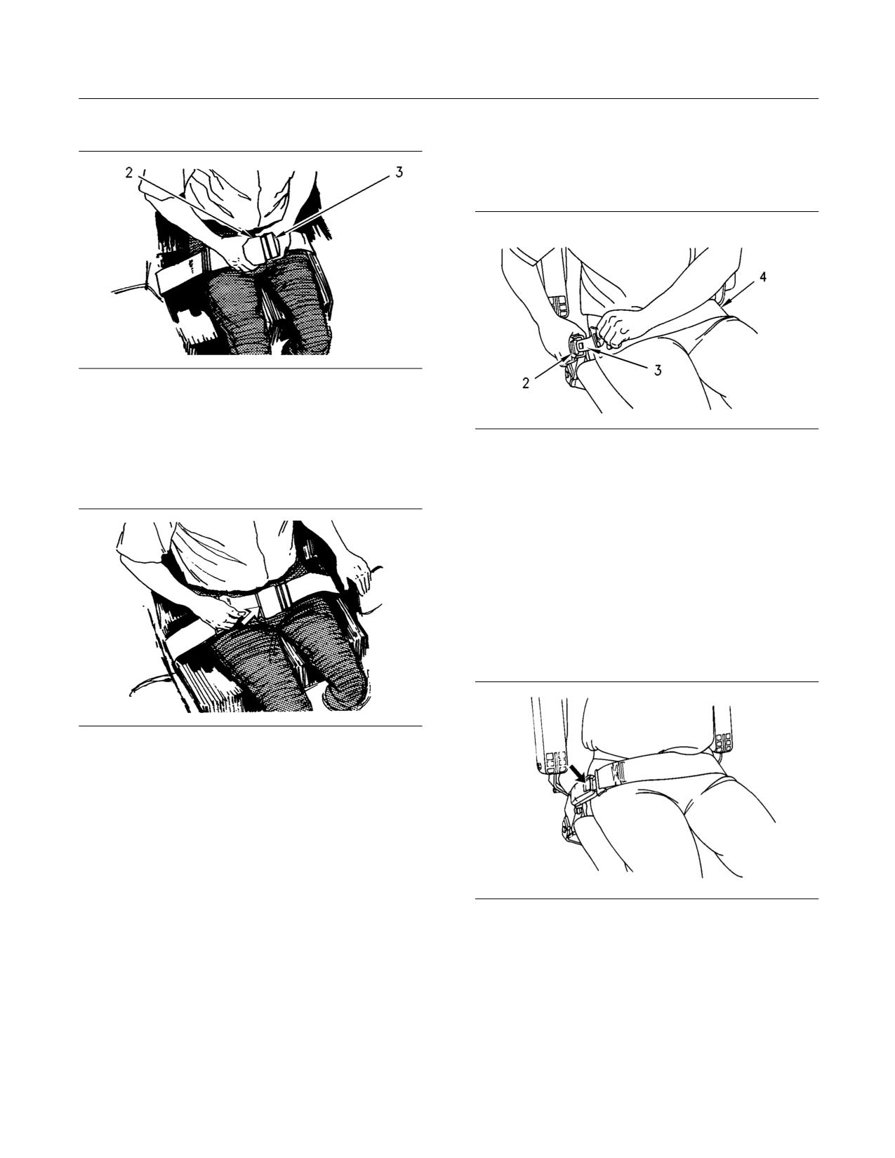
62
SEBU8407-06
Operation Section
Machine Operation
Fastening The Seat Belt
Seat Belt Adjustment for
Retractable Seat Belts
Fastening The Seat Belt
g00932818
Illustration 30
Fasten the seat belt catch (3) into the buckle (2).
Make sure that the seat belt is placed low across the
g00867598
Illustration 32
lap of the operator.
Pull seat belt (4) out of the retractor in a continuous
Releasing The Seat Belt
motion.
Fasten seat belt catch (3) into buckle (2). Make sure
that the seat belt is placed low across the lap of the
operator.
The retractor will adjust the belt length and the
retractor will lock in place. The comfort ride sleeve
will allow the operator to have limited movement.
Releasing The Seat Belt
g00100717
Illustration 31
Pull up on the release lever. This will release the seat
belt.
g00039113
Illustration 33
Push the release button on the buckle in order to
release the seat belt. The seat belt will automatically
retract into the retractor.
SEBU8407-06
63
Operation Section
Machine Operation
Extension of the Seat Belt
When using retractable seat belts, do not use seat
belt extensions, or personal injury or death can
result.
The retractor system may or may not lock up de-
pending on the length of the extension and the
size of the person. If the retractor does not lock
up, the seat belt will not retain the person.
Longer, non-retractable seat belts and extensions for
the non-retractable seat belts are available.
Caterpillar requires only non-retractable seat belts to
be used with a seat belt extension.
Consult your Cat dealer for longer seat belts and for
information on extending the seat belts.
i04077189
Operator Controls
SMCS Code: 7300; 7451
Note: Your machine may not be equipped with all
of the controls that are discussed in this topic.
The operation section is a reference for the new
operator and a refresher for the experienced
operator. This section includes descriptions of
gauges, switches, machine controls, attachment
controls, transportation, and towing information.
Illustrations guide the operator through correct
procedures of checking, starting, operating, and
stopping the machine. Operating techniques that
are outlined in this publication are basic. Skill and
techniques develop as the operator gains knowledge
of the machine and the capabilities of the machine.
Note: Simple hydromechanical work tools may be
shipped without hydraulic oil. Uneven movement
may occur until all the air has been removed from the
work tool. You may need to add hydraulic oil to the
machine after the machine fills the circuits of the work
tool. Refer to Operation and Maintenance Manual,
“Hydraulic System Oil Level - Check” for the proper
procedure for checking the hydraulic oil level.
Note: If the machine is not equipped with a cab that
is enclosed, Caterpillar recommends the use of a
flying object guard. If the machine is equipped with
an enclosed cab, operate the machine with the cab
door in the CLOSED position.
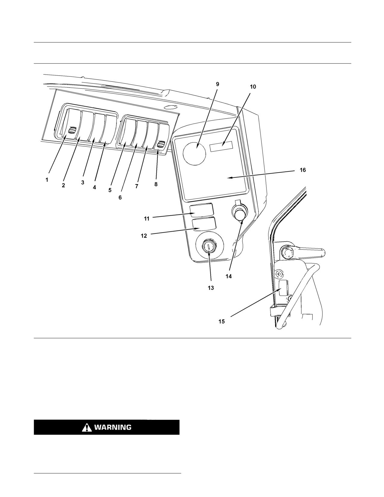
64
SEBU8407-06
Operation Section
Machine Operation
Left Side Controls
g01210307
Illustration 34
(1) Auxiliary Hydraulic Pressure Release
(6) Auxiliary Electrical Control
(12) Parking Brake
(2) Hydraulic Lockout and Interlock Override
(7) Automatic Level Control
(13) Engine Start Switch
(3) Rear Work Lights
(8) Work Tool Coupler Control
(14) 12 volt Plug
(4) Front Work Lights
(9) Fuel Level Gauge
(15) Window Wiper and Window Washer
(5) Multifunction Switch for the Left Hand
(10) Service Hour Meter
(16) Alert Indicator Panel
Trigger
(11) Joystick Control Pattern
Auxiliary Hydraulic Pressure
Auxiliary Hydraulic Pressure Release - After the
engine has run in order to charge the accumulator,
Release (1)
turn the ignition switch to the OFF position. Turn
the ignition switch to the ON position. Release the
parking brake. Push up on the locking tab and press
the bottom of the switch in order to release the
Personal injury or death can result from the work
pressure in the Standard Flow Auxiliary Circuit and
tool falling.
the High Flow Auxiliary Circuit. Hold the switch for 4
to 5 seconds and release the switch.
Fully lower the loader arms before you release the
hydraulic system pressure.
SEBU8407-06
65
Operation Section
Machine Operation
Note: The operator must remain in the seat with the
Switch on the Cab Door
armrests in the LOWERED position in order for the
control to function. If equipped, the front door must
A switch is provided on the cab door that prevents
be closed.
the work tool from operating when the cab door is
open. If the cab door is not installed, install a jumper
Note: The pressure in the secondary circuit is not
wire between Terminal 2 and Terminal 4 in the wiring
affected by this switch. Refer to Operation and
harness connector for the Window Wiper. Refer to
Maintenance Manual, “Work Tool Coupler Operation
Special Instruction, REHS1738, “Installing the Cab
: Secondary Auxiliary Circuit” for the procedure to
Door and Mounting Group” for more information
release the pressure.
about the cab door.
Note: When the door is installed, remove the jumper
Hydraulic Lockout and Interlock
wire from the connector plug before you connect
Override (2)
the harness. Damage to the door could occur if the
jumper is left in place.
Hydraulic Lockout - Press the top of
the switch in order to disable the hydraulic
Rear Work Lights (3)
functions. Return the switch to the middle
position in order to activate the hydraulic functions.
Rear Work Lights - Press the bottom
of the switch in order to turn on the lights.
Note: Activate the hydraulic shutoff when you are
Press the top of the switch in order to turn
roading the machine in order to prevent unplanned
off the lights.
movement of the work tool and the loader arms.
Interlock Override - The interlock override
Front Work Lights (4)
allows the auxiliary hydraulic circuits to
function with the armrests in the RAISED
Front Work Lights - Press the bottom
position. First bring the machine to a complete stop.
of the switch in order to turn on the lights.
Activate the continuous flow control that is located on
Press the top of the switch in order to turn
the left side joystick. Refer to the section “Joystick
off the lights.
Controls” for detailed information. Press the bottom
of the interlock override switch and release the switch
in order to activate the interlock override function. In
Multifunction Switch for the Left
order to turn off the interlock override and continuous
Hand Trigger (5)
flow, press the bottom of the switch and release the
switch again.
This switch is used to toggle the function of the trigger
on the left-hand joystick between Two Speed and the
Auxiliary Electrical Function “AUX 7”.
Two Speed
Inadvertent movement of the work tool may occur
if the interlock override function is used with work
Two Speed - Push the top of the switch
tools. This may result in personal injury or death.
in order to use the trigger for the two speed
Only use interlock override function for hand-held
control. Press the trigger and release the
work tools.
trigger on the front of the left-hand joystick in order
to activate rabbit mode. In order to return to single
Note: The alert indicator for the parking brake
speed, press the trigger and release the trigger again.
will light when the interlock override is activated.
When the interlock override is deactivated, press
Note: Keep the work tool close to the ground when
the parking brake switch in order to disengage the
you travel in rabbit mode. This method will maximize
parking brake and activate the hydraulic functions.
the stability of the machine.
NOTICE
Note: Do not move the multifunction switch while
Do not leave the machine unattended while you have
the Two Speed function is active. Ensure that the
the interlock override function activated.
machine is in single speed mode before the Auxiliary
Electrical Function “AUX 7” is activated.
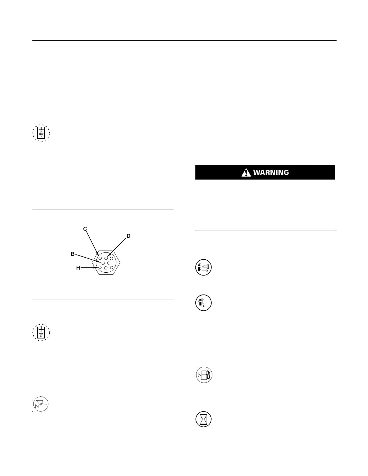
66
SEBU8407-06
Operation Section
Machine Operation
Note: The creeper must be turned off in order to
Note: The Automatic Level Control keeps a load at
shift the machine into two speed. If you activate the
the selected angle when the lift arms are raised. The
creeper, the machine will return to single speed. If
Automatic Level Control is not designed to maintain
you set the parking brake, the machine will return to
the selected angle of the work tool when the lift arms
low speed.
are lowered.
Note: If Automatic Level Control and Ride Control
Auxiliary Electrical Function “AUX 7”
are selected, Ride Control will be activated at the
Activation Speed and the Automatic Level Control
Note: If the switch is not present, the trigger on the
will be deactivated. When the machine reaches
left-hand joystick only provides this auxiliary function.
the Deactivation speed, the Ride Control will be
deactivated and the Automatic Level Control will be
Auxiliary Electrical Function “AUX 7” -
activated. Refer to the section on “Ride Control” for
Push the bottom of the switch in order to
more details.
activate the seventh auxiliary electrical
function. Pull the trigger and hold the trigger on the
left-hand joystick in order to provide electrical power
Work Tool Coupler Control (8)
to pin (B) on the work tool connector on the loader
arm. Release the trigger in order to deactivate the
control.
Improper Attachment of the Work Tool could result
Auxiliary Electrical Control “AUX
in injury or death.
8”
Do not operate the machine without confirmation
that the coupler pins are fully engaged. Follow the
operating procedures in the Operation and Main-
tenance Manual.
Work Tool Coupler Control - The work tool coupler
control controls the engagement of the coupler pins.
Disengaged - Push the red button upward
and press the bottom of the switch. Hold
the switch in the downward position until
the coupler pins disengage.
Engaged - Press the top of the switch and
g01107114
hold the top of the switch until the coupler
Illustration 35
pins engage.
Typical electrical connection on the loading arm
Auxiliary Electrical Control “AUX 8”
Refer to Operation and Maintenance Manual, “Work
(6) - The auxiliary electrical control
Tool Coupler Operation” for the proper procedure for
supplies continuous electrical power to pin
the work tool coupler.
(H) on the connector for the work tool on the loader
arm. Press on the bottom of the switch in order to turn
Fuel Level Gauge (9)
on electrical power. Press on the top of the switch in
order to turn off electrical power.
Fuel Level Gauge - The needle in the red
range indicates low fuel.
Automatic Level Control (7)
Automatic Level Control - The Automatic
Service Hour Meter (10)
Level Control maintains the approximate
selected angle of the work tool as the
Service Hour Meter - The service hour
loader lift arms are raised. Press on the bottom of the
meter should be used to determine service
switch in order to activate the automatic level control.
hour maintenance intervals.
Press on the top of the switch in order to deactivate
the automatic level control.
SEBU8407-06
67
Operation Section
Machine Operation
Joystick Control Pattern (11)
12 volt plug (14)
The switch for the Joystick Control Pattern has a
12 volt plug
number “1” on one side and a number “2” on the
other side. When you start the machine, choose “1 -
Window Wiper and Window Washer
Caterpillar” or “2 - Alternate” in order to release the
parking brake. The numbers on the Alert Indicator
(15)
panel will blink until a pattern is selected. Once a
pattern has been selected, activating the parking
Window Wiper and Window Washer -
brake will not affect the selection of the pattern.
Move the switch to the middle position in
Refer to the section “Joystick Controls” for detailed
order to turn on the wiper. Press on the top
information.
of the switch in order to operate the washer. Press on
the bottom of the switch in order to turn off the wipers.
Parking Brake Control (12)
Alert Indicator Panel (16)
Parking Brake Control - Press on the
right side of the switch and release the
Refer to the section Operator and Maintenance
switch in order to engage the parking brake.
Manual, “Alert Indicators” for a description about the
The same operation will disengage the parking brake.
indicators.
Note: The parking brake will engage when the engine
is stopped. The parking brake will engage when the
armrests are moved to the RAISED position. The
parking brake will engage when the operator leaves
the operator seat for a time. The parking brake will
engage when the interlock override is activated.
Note: If the switch for the Joystick Control Pattern
is installed, select a pattern in order to release the
parking brake.
Engine Start Switch (13)
OFF - Insert the engine start switch key
only from the OFF position and remove
the engine start switch key only from the
OFF position. Turn the engine start switch key to the
OFF position in order to stop the engine. In the OFF
position, there is no power to most electrical circuits
on the machine. The cab dome light is operational
even when the engine start switch is in the OFF
position.
ON - Turn the engine start switch key
clockwise to the ON position in order to
activate all of the cab circuits.
START - Turn the engine start switch key
clockwise to the START position in order to
crank the engine. Release the engine start
switch key after the engine starts and the engine start
switch key returns to the ON position.
Note: If the engine fails to start, the turn the engine
start switch key to the OFF position in order to attempt
to start the engine again. Refer to the Operation and
Maintenance Manual, “Engine Starting” for more
details about starting the engine.
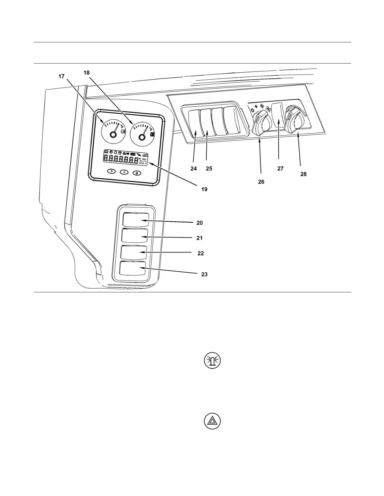
68
SEBU8407-06
Operation Section
Machine Operation
Right Side Controls
g01210277
Illustration 36
(17) Coolant Temperature
(21) Hazard Flashers
(25) Ride Control
(18) Hydraulic Oil Temperature
(22) Roading Lights
(26) Fan Speed Control
(19) Digital Display Window
(23) Turn Signals
(27) Air Conditioning Control
(20) Beacon Switch
(24) Creeper Control
(28) Temperature Control
Coolant Temperature (17)
Beacon Switch (20)
Coolant Temperature gauge
Beacon - Press on the left side of the
switch in order to turn on the beacon. Press
the right side of the switch in order to turn off
Hydraulic Oil Temperature (18)
the beacon. The receptacle for the beacon is located
on the upper left corner on the rear of the cab.
Hydraulic Oil Temperature gauge
Digital Display Window (19)
Hazard Flashers (21)
Refer to the section “Digital Display Window” for
Hazard Flasher Control - Press on the
detailed information.
left side of the switch in order to activate the
hazard flashers. Press on the right side of
the switch in order to deactivate the hazard flashers.
SEBU8407-06
69
Operation Section
Machine Operation
Roading Lights (22)
• Activation speed - 8 km/h (5.0 mph) for Ride
Control
Roading Lights - Move the switch to
the middle position in order to turn on the
• Deactivation speed - 6 km/h (3.7 mph) for Ride
control panel lights and position lights.
Control.
Press on the left side of the switch in order to turn on
the front low beams. Press on the right side of the
Note: If Automatic Level Control and Ride Control
switch in order to turn off the lights.
is selected, Ride Control will be activated at the
Activation Speed and the Automatic Level Control
will be deactivated. When the machine reaches
Turn Signals (23)
the Deactivation speed, the Ride Control will be
deactivated and the Automatic Level Control will be
Turn Signals - Press on the left side of
activated.
the switch in order to turn on the left turn
signals. Press on the right side of the switch
Fan Speed Control (26)
in order to turn on the right turn signals. Move the
switch to the middle position in order to turn off the
Fan Speed Control
turn signals.
Creeper Control (24)
Air Conditioner Control (27)
The Creeper Control allows the operator to select
a maximum machine travel speed at full joystick
Air Conditioner Control
movement. Use creeper control for operations that
require slow, constant speed.
Creeper Control - In order to activate
the creeper control, stop the machine and
Temperature Control (28)
return the joysticks to the neutral position.
Press the bottom of the switch in order to turn on the
Temperature Control
creeper control. In order to deactivate the creeper
control, stop the machine and return the joysticks to
the neutral position. Press the top of the switch in
order to turn off the creeper control.
Refer to “Digital Display Window” for detailed
information about the creeper speed control.
Ride Control (25)
Ride Control assists in smoothing the ride of the
machine. Travel over rough terrain causes bucket
movement. The ride control system uses the lift
cylinders as shock absorbers. The lift cylinders
dampen the forces from the bucket.
Ride Control - Press the bottom of the
switch in order to turn on the ride control.
Ride control will activate and the alert
indicator will illuminate at the appropriate speed.
Press the top of the switch in order to turn off the
ride control.
Note: The ride control will deactivate and the
indicator will not be illuminated at the appropriate
speed. The ride control will also deactivate if the tilt
function for the work tool is operated.
The following approximate speeds apply:
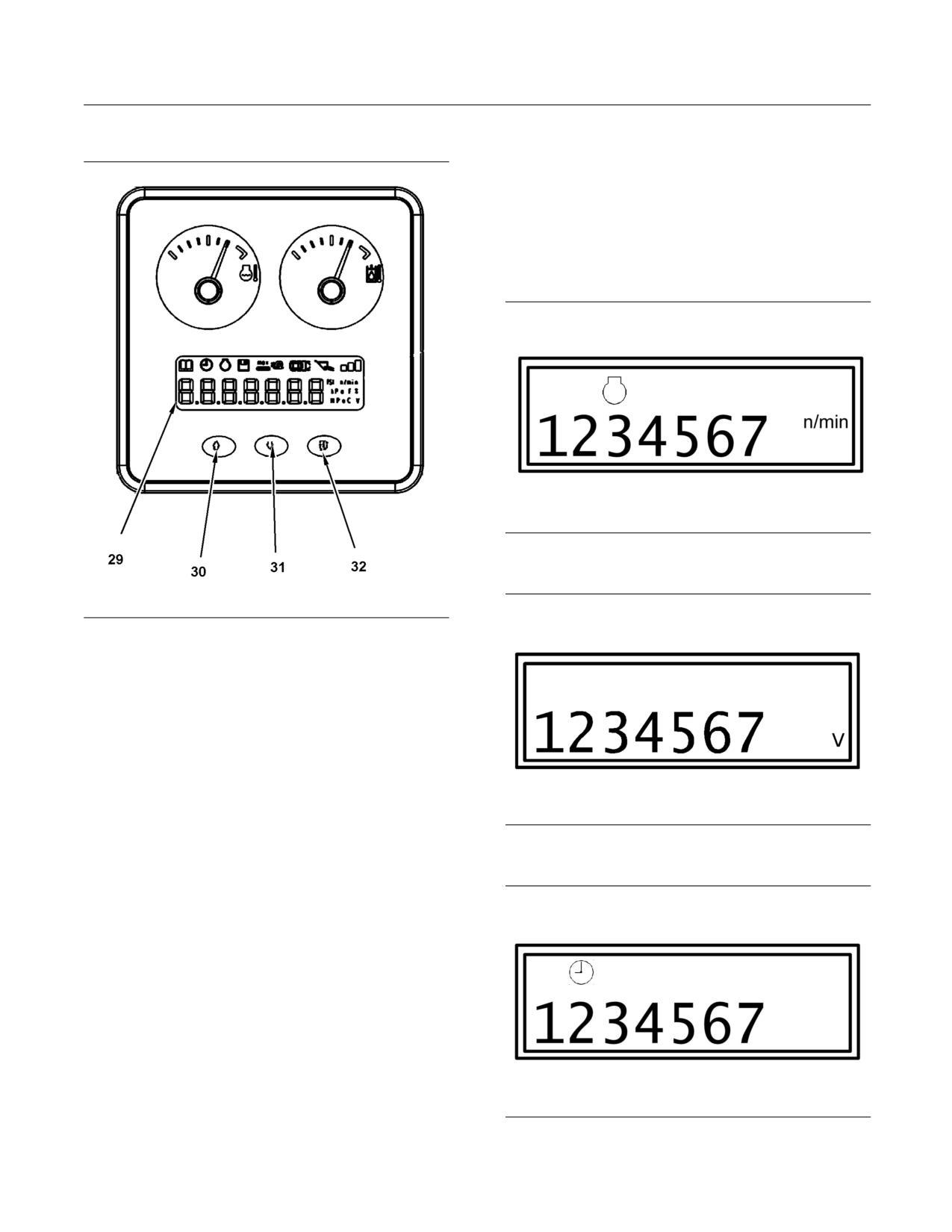
70
SEBU8407-06
Operation Section
Machine Operation
Digital Display Window
In order to display the AccuGrade menu, press the
scroll down key (31) and press the function key (32)
at the same time. Refer to the AccuGrade section
below.
Operator Mode 1 - Display Screen
Three displays are available in this mode: Digital
Tachometer, System Voltage, and Job Clock.
g01242569
Illustration 38
Representation of the Digital Tachometer (default start-up mode)
g01227636
Illustration 37
(29) Digital Display Window
(30) Scroll Up Key
(31) Scroll Down Key
(32) Function Selector
General Description
The digital display window (29) shows some basic
information about the machine. The Engine Speed,
System Voltage, Job Clock, Work tool Control, “Drive
Mode Control”, and Creeper Control are displayed.
The digital display window is used to set the work
g01242622
Illustration 39
tool control. The digital display window is used to set
Representation of the System Voltage
the Creeper Control. The Function Selector (32) is
used to toggle between modes that are available:
• Operator Mode 1 - Display Screen
• Operator Mode 2 - Work Tool Control
• Operator Mode 3 - Drive Mode Control
• Operator Mode 4 - Creeper Control
The scroll up key (30) and the scroll down key (31)
are used to toggle between screens or settings in
a mode.
g01242648
Illustration 40
Representation of the Job Clock
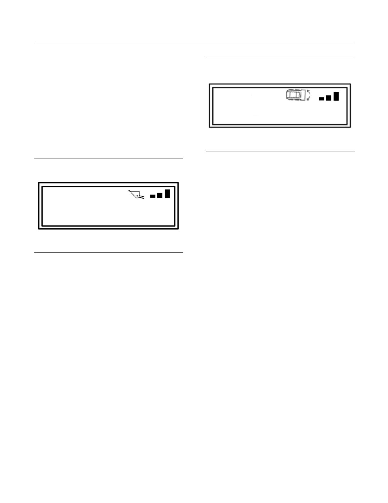
SEBU8407-06
71
Operation Section
Machine Operation
The default start-up mode is the Digital Tachometer.
Use the “Scroll Up” button and the “Scroll Down”
button in order to change the screen. The Job Clock
can be reset by holding the “Scroll Up” and the “Scroll
Down” buttons for 3 seconds.
Operator Mode 2 - Work Tool Control
In Operator Mode 1, push the “Function Selector”
button 1 time. The “Work Tool Control” screen is used
in order to display the current setting for the response
of the lift and tilt functions of the machine. Use the
“Scroll Up” button and the “Scroll Down” button in
order to change to a different setting.
g01892289
Illustration 42
Representation of the “Drive Mode Control”
The “Drive Mode Control” has three settings:
• Standard Mode - 1 Bar
• Intermediate Mode - 2 Bars
• Maximum Mode - 3 Bars
Note: The “Drive Mode Control” setting will not
change when the ignition switch is turned off.
g01242657
Note: The machine will start, stop, and steer more
Illustration 41
aggressively with each progressive drive control
Representation of the Work Tool Control
mode. Test drive the machine in an open area in order
to test the operating characteristics of the machine.
The Work Tool Control mode has three settings:
Operator Mode 4 - Creeper Control
• Fine Control - 1 Bar
In Operator Mode 1, push the “Function Selector”
• Medium Control - 2 Bars
button 3 times. The “Creeper Control” screen is used
in order to display the current setting for the creeper
• Coarse Control - 3 Bars
control. Use the “Scroll Up” button and the “Scroll
Note: The Work Tool Control setting will not change
Down” button in order to change to a different setting
when the ignition switch is turned off.
for the Creeper Control.
Note: The “Creeper Control” setting will not change
Operator Mode 3 - Drive
when the ignition switch is turned off. Refer to the
section “Creeper Control” for operation of the switch.
In Operator Mode 1, push the “Function Selector”
button 2 times. The “Drive Mode Control” screen
is used in order to display the current setting of
the “Drive Mode Control” functions. Use the “Scroll
Up” button and the “Scroll Down” button in order to
change to a different setting.
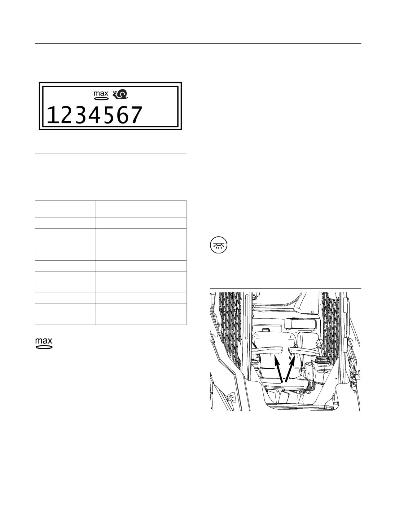
72
SEBU8407-06
Operation Section
Machine Operation
3. In order to set the benchmark, press the scroll up
key (30) and press the scroll down key (31) at the
same time. Hold the keys until the value is set
in the computer (approximately 3 seconds). The
screen will display a “0” and the screen will flash
once.
4. Press the trigger and release the trigger on
the right-hand joystick in order to enable the
AccuGrade automatic controls. Operate the
implement joystick or operate the thumb wheel
in order to override the automatic controls
temporarily.
5. Press the trigger and release the trigger on
g01242658
Illustration 43
the right-hand joystick in order to disable the
Representation of the Creeper Control
AccuGrade automatic controls.
The Creeper Control has the following ten settings:
6. Press the scroll up key (30) and hold the scroll up
key in order to exit AccuGrade.
Table 22
Approximate Percent of
Setting
Other Features in the Cab
Full Speed
1
5%
Cab Dome Light
2
7%
Cab Dome Light - Press on either side of
3
10%
the light in order to turn on the light. Move
the light to the middle position in order to
4
13%
turn off the light.
5
17%
6
24%
Interlock Control
7
37%
8
57%
9
80%
10
100%
Setting 10 - The “MAX” icon will appear
at the maximum setting.
AccuGrade (If Equipped)
The following instructions are a quick reference for
the AccuGrade. For detailed instructions for the
AccuGrade, refer to the Operation and Maintenance
Manual, SEBU8278.
1. Ensure that the Laser Receiver is attached to the
work tool and attached to the machine properly.
g01231722
Illustration 44
2. In order to display the AccuGrade menu, press
Armrests
the scroll down key (31) and press function key
(32) at the same time.
Interlock Control - Move the armrests to the
RAISED position in order to lock out the hydraulic
controls.
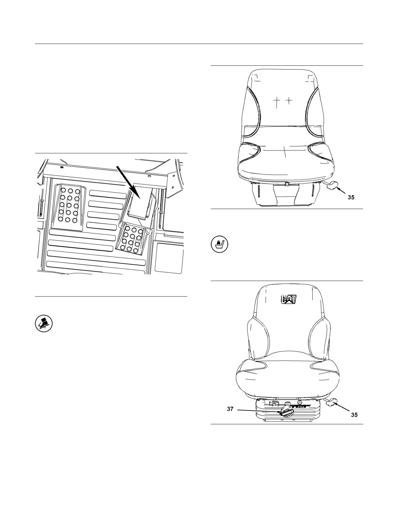
SEBU8407-06
73
Operation Section
Machine Operation
Note: When the armrests are moved to the RAISED
Standard Seat
position, the parking brake will engage. Move the
armrests to the LOWERED position and push the
switch for the parking brake in order to activate the
hydraulic controls.
Note: When you start the engine, the parking brake
must be disengaged in order for the hydraulic controls
to be activated. If the armrests are raised and lowered
during operation, disengage the parking brake in
order for the hydraulic controls to be activated.
Accelerator Control
g01231724
Illustration 46
(35) Fore/Aft Adjustment
Standard Seat
Suspension Seat
g01231723
Illustration 45
Accelerator Control - Push down on
the accelerator pedal in order to increase
engine speed. Release the accelerator
pedal in order to decrease engine speed. The
accelerator pedal will return to the setting of the
governor control.
g01243184
Illustration 47
(35) Fore/Aft Adjustment
(37) Adjustment for the suspension
Fore/Aft lever (35) - Move the lever in order to
adjust the seat.
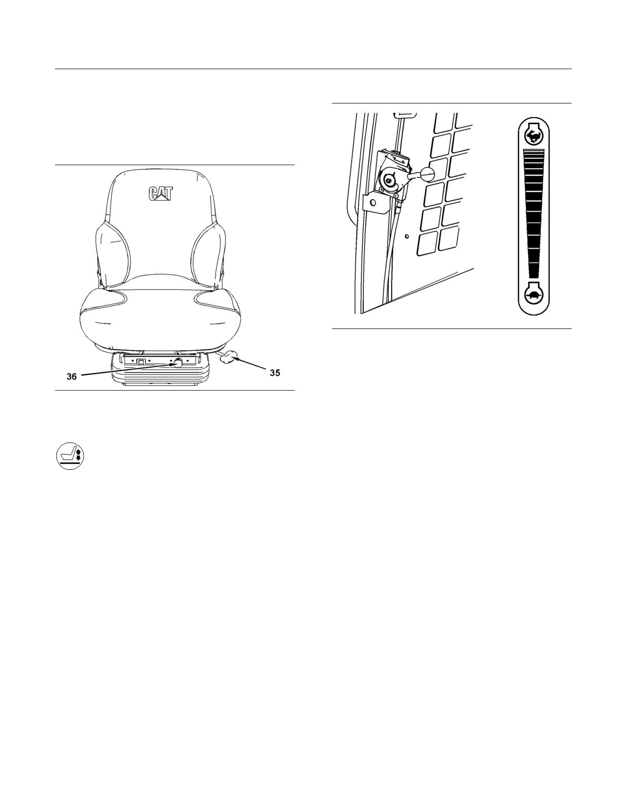
74
SEBU8407-06
Operation Section
Machine Operation
Height (37) - Turn the knob in order to adjust the
Governor Control
suspension of the seat. Turn the knob clockwise for
a heavier person. Turn the knob counterclockwise
for a lighter person.
Air Suspension Seat
g01231729
Illustration 49
Governor Control - Use the governor control when
you want to set a constant engine speed. Move the
lever upward in order to increase engine speed.
g01231726
Move the lever downward in order to decrease
Illustration 48
engine speed.
(35) Fore/Aft Adjustment
(36) Adjustment for the suspension
Joystick Controls
Seat Adjustment
The joystick control that is described in this section
is for the Caterpillar Joystick Control Pattern. This
pattern is the default for machines that are NOT
equipped with the option for the Selectable Control
Push in the knob (36) in order to increase the stiffness
Pattern or the Dedicated Control Pattern.
of the suspension. Pull the knob in order to decrease
the stiffness of the suspension.
Refer to the section “Selectable Control Pattern and
Dedicated Control Pattern” below for instructions
Note: The engine start switch key must be in the ON
about the Alternate Joystick Control pattern and the
position in order to increase the stiffness of the seat.
Dedicated Control Pattern.
Refer to the section “Auxiliary Hydraulic Controls”
below for instructions about the Auxiliary Hydraulic
Controls .
Your machine may not be equipped with all of the
controls that are discussed in this topic.
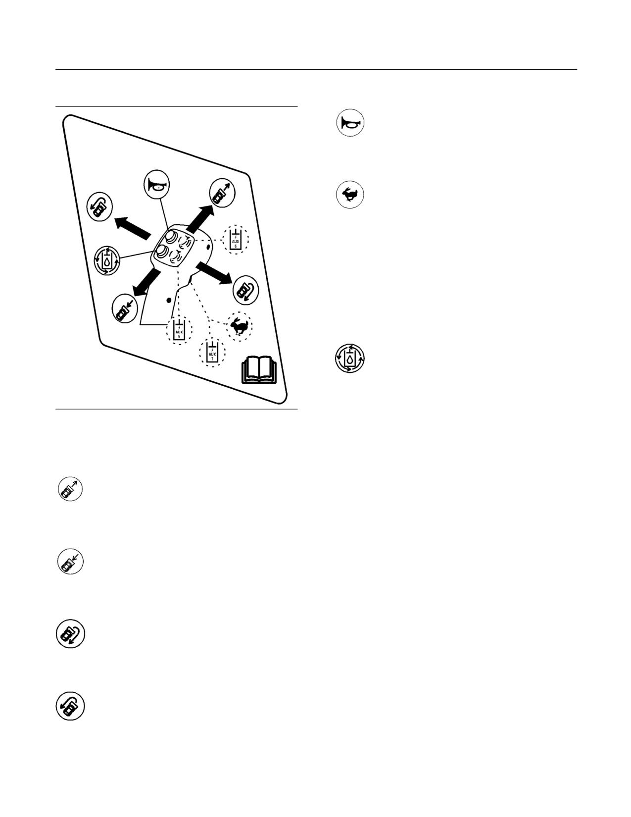
SEBU8407-06
75
Operation Section
Machine Operation
Left Hand Joystick
Horn
Horn - Press the switch in order to sound
the horn. Use the horn in order to alert
personnel.
Two Speed Control
Two Speed - Press the trigger and release
the trigger on the front of the left-hand
joystick in order to activate rabbit mode.
In order to activate rabbit mode, the Multifunction
Switch must also be in the Two Speed position. Refer
to “Multifunction Switch for the Left Hand Trigger (5)”
above for instructions about the switch.
Note: Keep the work tool close to the ground when
you travel in rabbit mode. This method will maximize
the stability of the machine.
Continuous Flow Control
Continuous Flow - The continuous
flow control supplies continuous flow of
hydraulic fluid to the auxiliary hydraulic
circuit without continuously holding the auxiliary
hydraulic control. Press either one of the two auxiliary
hydraulic switches (1) or (2) that are located on the
g01259300
right side joystick and hold that switch. If equipped,
Illustration 50
you may also move the thumb wheel on the right
Instruction Decal for the Left Hand Joystick
side joystick and hold the thumb wheel. Press the
continuous flow switch on the left-hand joystick and
Forward
release the continuous flow switch. Immediately
release the auxiliary hydraulic switch or the thumb
Forward Travel - Push the joystick
wheel after you release the continuous flow switch.
forward in order to travel forward.
The continuous flow function will be activated if the
operator releases the auxiliary hydraulic switch within
one second of pressing the continuous flow switch.
Backward
Press on either the auxiliary hydraulic control or the
continuous flow switch in order to stop the flow to
Backward Travel - Pull back on the
the auxiliary circuit.
joystick in order to travel in reverse.
Right Turn
Right Turn - Move the joystick to the right
in order to turn the machine to the right.
Left Turn
Left Turn - Move the joystick to the left in
order to turn the machine to the left.
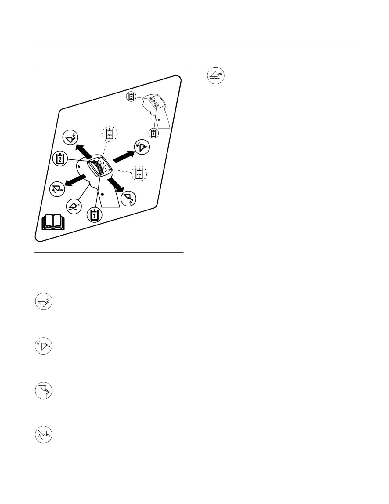
76
SEBU8407-06
Operation Section
Machine Operation
Right Hand Joystick
Float
Float - Float allows the work tool to follow
the contour of the ground.
The following conditions will activate the float function
on the machine.
Move the joystick to the lower position and press
the trigger. Float is activated. You may now release
the trigger.
For an earlier machine that is not updated, move the
joystick to the lower position. Press the trigger and
release the trigger. Float is activated.
Once the float function is engaged, the joystick can
be returned to the neutral position without affecting
the float function. Float will remain engaged until the
trigger on the right-hand joystick is pressed again.
The float function will disengage also when the
bucket is raised or when the bucket is lowered.
Note: These changes affect the following serial
numbers: (S/N: JAY3086-UP), (S/N: DWS1377-UP),
(S/N: MST2570-UP), (S/N: RED1669-UP),
(S/N: JWF2014-UP), (S/N: MAS1735-UP),
(S/N: GCP1475-UP), (S/N: MBT326-UP), (S/N:
g01259303
Illustration 51
JSP289-UP), and (S/N: JMP309-UP). Serial numbers
Instruction Decal for the Right Hand Joystick
earlier than the listed will be affected if the software
for the machine control has been updated.
Lower
Note: If the float function is enabled, the AccuGrade
Lower - Push the joystick forward in order
option is disabled.
to lower the work tool.
Auxiliary Shake Out Mode
Auxiliary Shake Out mode is an aggressive
Dump
movement of the work tool in order to dislodge
effectively wet material or sticky material.
Dump - Move the joystick to the right in
order to tilt the work tool downward.
Move the thumb wheel over the NEUTRAL position
three times within a 2 second period in order to
activate Auxiliary Shake Out mode. Auxiliary Shake
Raise
Out mode will remain engaged while the thumb wheel
is moved back and forth over the NEUTRAL position.
Raise - Pull the joystick backward in order
Normal auxiliary control mode will return when the
to raise the work tool.
movement of the thumb wheel is discontinued.
Selectable Control Pattern and
Tilt Back
Dedicated Control Pattern
Tilt Back - Move the joystick to the left in
order to tilt the work tool upward.
If your machine is equipped with a Selectable Control
Pattern or the Dedicated Control Pattern, there are
two options for the joystick control:
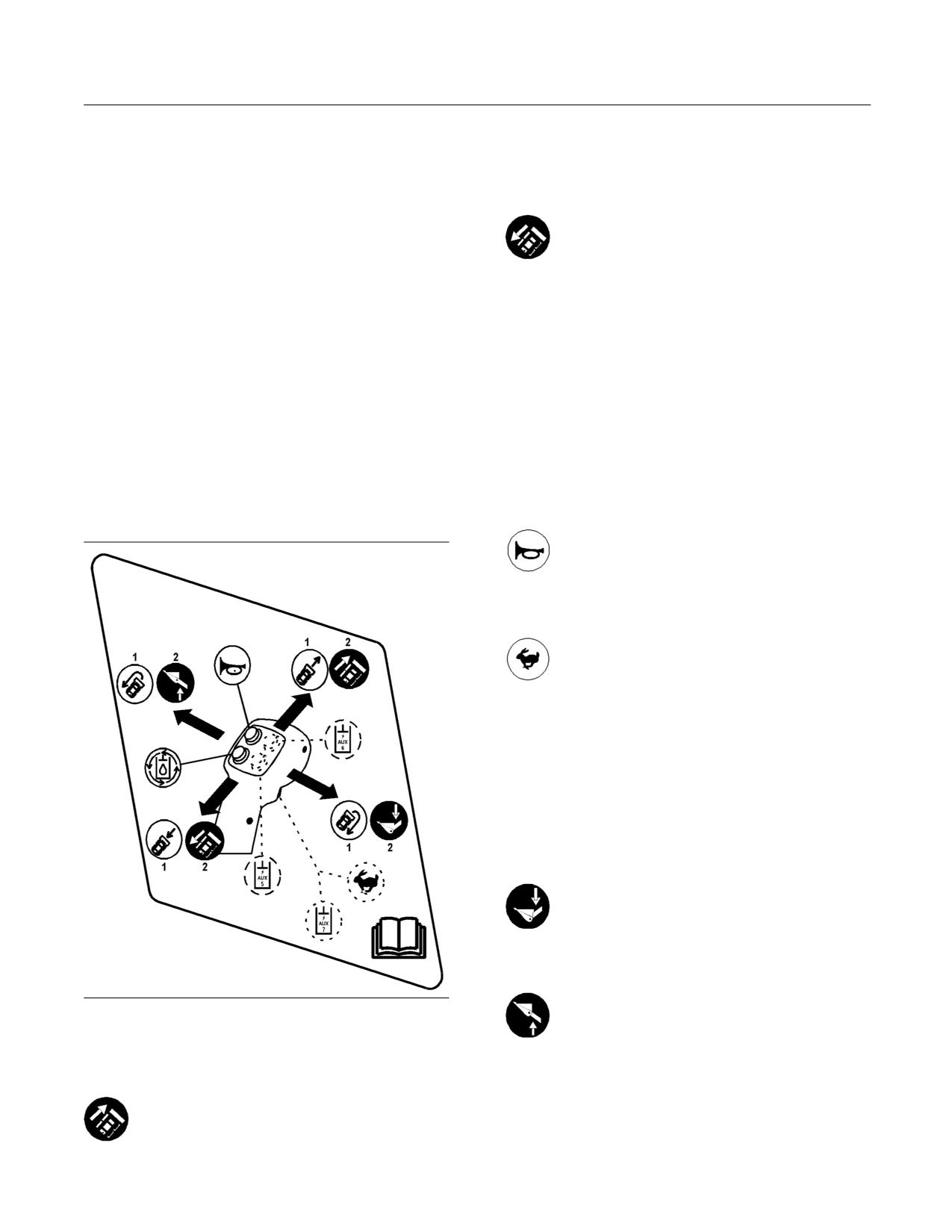
SEBU8407-06
77
Operation Section
Machine Operation
• The alert indicator “1” will light when the Caterpillar
Push both joysticks forward equally in order to move
Joystick Control Pattern is activated. Refer to the
the machine in a straight line.
section “Joystick Controls” above for instructions
about the Caterpillar Joystick Control Pattern in
Reverse Drive
illustration 52 and in illustration 53 with the label
“1”.
Reverse - Pull the left-hand joystick
backward in order to move the left side of
• The alert indicator “2” will light when the Alternate
the machine backward.
Joystick Control Pattern is activated.
Pull both joysticks backward equally in order to move
The following instructions reflect the operation of
the machine backward in a straight line.
the joysticks when the Alternate Joystick Control
Pattern is selected. The Alternate Joystick Control
Right Turn
Pattern changes the control of the work tool and the
movement of the machine. The changes in the control
Push the left joystick forward in order to turn the
are indicated in illustration 52 and in illustration 53
machine to the right.
with the label “2”.
Push the left joystick forward and pull the right
Refer to the section “Auxiliary Hydraulic Controls”
joystick backward in order to turn the machine rapidly
below for instructions about the Auxiliary Hydraulic
to the right.
Controls .
Horn
Left Hand Joystick
Horn - Press the switch in order to sound
the horn. Use the horn in order to alert
personnel.
Two Speed Control
Two Speed - Press the trigger and release
the trigger on the front of the left-hand
joystick in order to activate rabbit mode.
In order to activate rabbit mode, the Multifunction
Switch must also be in the Two Speed position. Refer
to “Multifunction Switch for the Left Hand Trigger (5)”
above for instructions about the switch.
Note: Keep the work tool close to the ground when
you travel in rabbit mode. This method will maximize
the stability of the machine.
Lower
Lower - Move the joystick to the right in
order to lower the work tool.
Raise
Raise - Move the joystick to the left in
g01259305
Illustration 52
order to raise the work tool.
Instruction Decal for the Left Hand Joystick
Forward Drive
Forward - Push the left-hand joystick
forward in order to move the left side of the
machine forward.
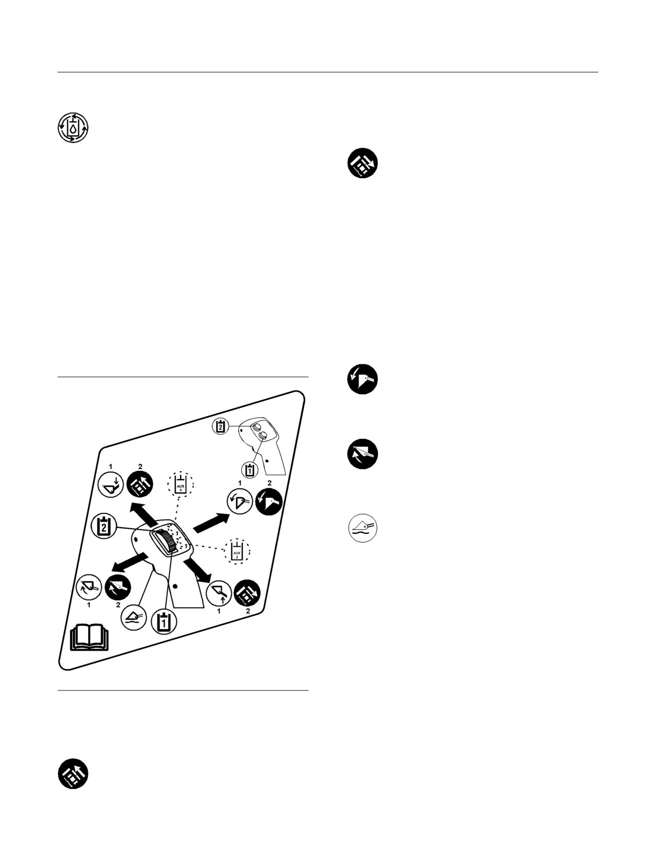
78
SEBU8407-06
Operation Section
Machine Operation
Continuous Flow Control
Push both joysticks forward equally in order to move
the machine forward in a straight line.
Continuous Flow - The continuous
flow control supplies continuous flow of
Reverse Drive
hydraulic fluid to the auxiliary hydraulic
circuit without continuously holding the auxiliary
Reverse - Pull the right-hand joystick
hydraulic control. Press either one of the two auxiliary
backward in order to move the right side of
hydraulic switches (1) or (2) that are located on the
the machine backward.
right side joystick and hold that switch. If equipped,
you may also move the thumb wheel on the right
Pull both joysticks backward equally in order to move
side joystick and hold the thumb wheel. Press the
the machine backward in a straight line.
continuous flow switch on the left-hand joystick and
release the continuous flow switch. Immediately
Left Turn
release the auxiliary hydraulic switch or the thumb
wheel after you release the continuous flow switch.
Push the right joystick forward in order to turn the
The continuous flow function will be activated if the
machine to the left.
operator releases the auxiliary hydraulic switch within
one second of pressing the continuous flow switch.
Push the right joystick forward and pull the left
Press on either the auxiliary hydraulic control or the
joystick backward in order to turn the machine rapidly
continuous flow switch in order to stop the flow to
to the left.
the auxiliary circuit.
Dump
Right Hand Joystick
Dump - Move the joystick to the right in
order to tilt the work tool downward.
Tilt Back
Tilt Back - Move the joystick to the left in
order to tilt the work tool upward.
Float
Float - Float allows the work tool to follow
the contour of the ground.
The following conditions will activate the float function
on the machine.
Move the joystick to the lower position and press the
trigger on the right-hand joystick. Float is activated.
You may now release the trigger.
For an earlier machine that is not updated, move the
joystick to the lower position. Press the trigger and
release the trigger. Float is activated.
g01259306
Once the float function is engaged, the joystick can
Illustration 53
be returned to the neutral position without affecting
Instruction Decal for the Right Hand Joystick
the float function. Float will remain engaged until the
trigger on the right-hand joystick is pressed again.
Forward Drive
The float function will disengage also when the
bucket is raised or when the bucket is lowered.
Forward - Push the right-hand joystick
forward in order to move the right side of
the machine forward.
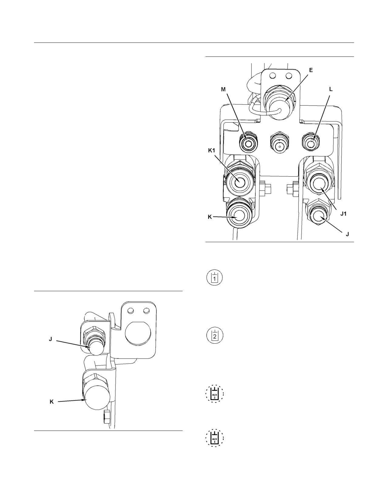
SEBU8407-06
79
Operation Section
Machine Operation
Note: These changes affect the following serial
numbers: (S/N: JAY3086-UP), (S/N: DWS1377-UP),
(S/N: MST2570-UP), (S/N: RED1669-UP),
(S/N: JWF2014-UP), (S/N: MAS1735-UP),
(S/N: GCP1475-UP), (S/N: MBT326-UP), (S/N:
JSP289-UP), and (S/N: JMP309-UP). Serial numbers
earlier than the listed will be affected if the software
for the machine control has been updated.
Note: If the float function is enabled, the AccuGrade
option is disabled.
Auxiliary Hydraulic Controls
If the work tool has a wiring harness, connect the
work tool harness to the electrical plug on the loader
arm. If your High Flow work tool does not have a
wiring harness, a Jumper Plug should be installed on
the electrical plug for the work tool control. Without
this Jumper Plug, the machine will not provide High
Flow to the work tool. Refer to your Parts Manual for
the current part number for the Jumper Plug.
Note: High flow mode requires an electrical
connection that is located on the loader arm. Refer
to Operation and Maintenance Manual, “Work Tool
Coupler Operation” or Operation and Maintenance
Manual, “Work Tool Operation” for additional details.
g01210266
Illustration 55
High Flow Connections
Note: If the high flow work tool does not have a wiring
harness, consult the Operation and Maintenance
Auxiliary Hydraulic Control (A1) - This
Manual for the work tool for the proper instructions
control provides hydraulic oil flow to the
for attaching the work tool.
auxiliary connections on the loader arm.
Engage the control in order to provide hydraulic oil
flow to the connector (K). For high flow work tools,
engage the control in order to provide hydraulic oil
flow to the connector (K1).
Auxiliary Hydraulic Control (A2) - This
control provides hydraulic oil flow to the
auxiliary connections on the loader arm.
Engage the control in order to provide hydraulic oil
flow to the connector (J). For high flow work tools,
engage the control in order to provide hydraulic oil
flow to the connector (J1).
Secondary Auxiliary Hydraulic Control
(C-) - This control provides hydraulic oil
flow to the auxiliary connections on the
loader arm. Press the control in order to provide
hydraulic oil flow to the connector (M).
Secondary Auxiliary Hydraulic Control
g01291620
Illustration 54
(C+) - This control provides hydraulic oil
Standard Auxiliary Connections
flow to the auxiliary connections on the
loader arm. Press the control in order to provide
hydraulic oil flow to the connector (L).
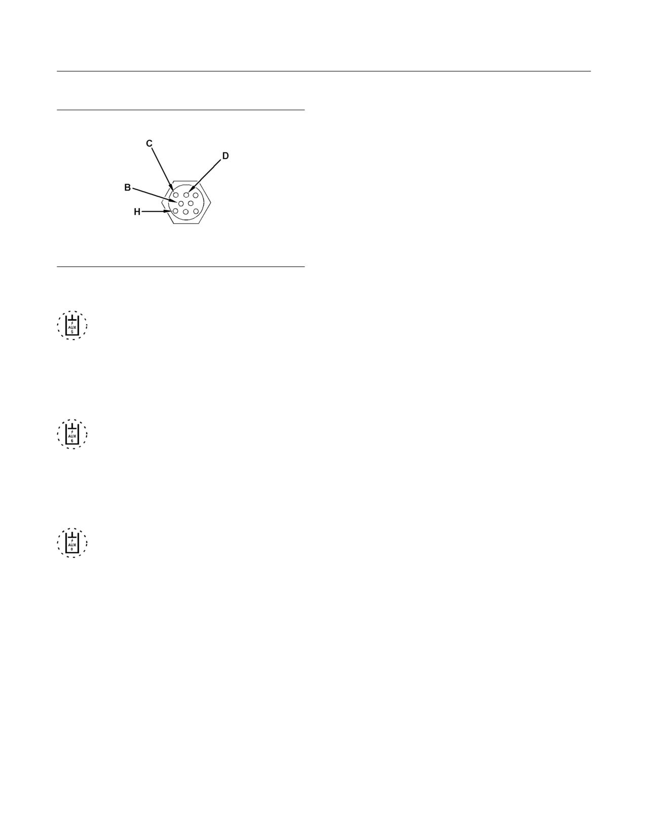
80
SEBU8407-06
Operation Section
Machine Operation
Auxiliary Electrical Control (E)
g01107114
Illustration 56
Typical electrical connection on the loading arm
Auxiliary Electrical Control “AUX 5”
(C2) - This control provides electrical
power in order to control a three-position
diverter valve that is located on some work tools.
Press the switch and hold the switch on the left-hand
joystick in order to provide electrical power to the
pin (D). Release the switch in order to deactivate
the control.
Auxiliary Electrical Control “AUX 6”
(C1) - This control provides electrical
power in order to control a three-position
diverter valve that is located on some work tools.
Press the switch and hold the switch on the left-hand
joystick in order to provide electrical power to the
pin (C). Release the switch in order to deactivate
the control.
Auxiliary Electrical Control “AUX 7” -
Press the left hand trigger and hold the
trigger in order to provide electrical power to
the pin (B). Release the trigger in order to deactivate
the control. Refer to “Multifunction Switch for the Left
Hand Trigger (5)” above for instructions about the
switch.
i03767633
Alert Indicators
SMCS Code: 7450; 7451
The alert indicators are located on the left side
overhead console.
Note: Your machine may not be equipped with all of
the indicators that are discussed in this topic.
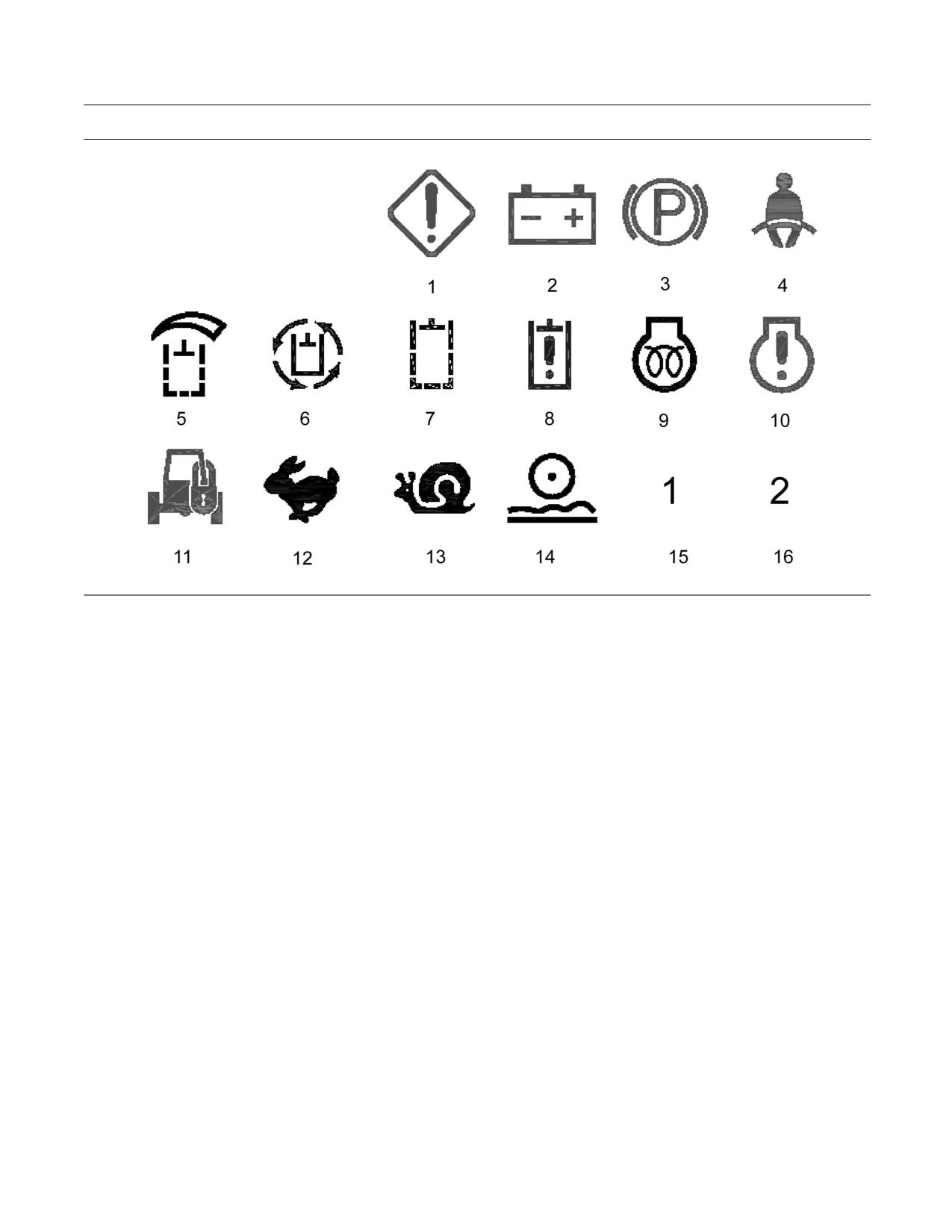
SEBU8407-06
81
Operation Section
Machine Operation
g01218926
Illustration 57
Left Side
1 - Driver Alert
• RED Oil Pressure
2 - Alternator Output
• AMBER Air Cleaner Indicator
3 - Parking Brake
11 - MSS Indicator
4 - Seat Belt
12 - Two Speed Control
5 - High Flow
13 - Creeper Control
6 - Continuous Flow
14 - Ride Control
7 - Work Tool System
15 - Caterpillar Joystick Control Pattern
• RED Work Tool Lockout
16 - Alternate Joystick Control Pattern
• AMBER Interlock Override
1 - Driver Alert This alert indicator will activate when
there is a problem which requires the operator's
8 - Hydraulics
attention.
• RED Hydraulic Temperature
Note: Other alert indicators that light or the gauges
may help investigate the cause of any problems.
• AMBER Hydraulic Filter Bypass
There are three levels of severity for the indicator:
9 - Glow Plug Starting Aid
•
Level 1 - If the alert indicator is on continuously,
10 - Engine Condition Indicator
stop the machine at the earliest convenience.
Investigate the cause. If no additional alert
• RED Coolant Temperature
indicators are illuminated, contact your Caterpillar
dealer or refer to the service manual.
82
SEBU8407-06
Operation Section
Machine Operation
• Level 2 - If the alert indicator is flashing and there
7 - Work Tool System
is no audible alarm, severe component damage
could occur. Change your operation or perform the
• This alert indicator will light red when the work tool
indicated maintenance.
lockout control is activated.
• Level 3 - If the alert indicator is flashing and there
• This alert indicator will light amber when the
is an audible alarm, injury to the operator or severe
interlock override is activated.
component damage could occur. Stop the machine
immediately and stop the engine.
8 - Hydraulics
2 - Alternator Output This alert indicator will light
• This alert indicator will light red and an audible alert
if there is a malfunction in the electrical system. If
will sound when the temperature of the hydraulic
this alert indicator comes on, the system voltage is
oil is too high. If this indicator comes on, stop
too high for normal machine operation or too low for
the machine immediately. Stop the engine and
normal machine operation.
investigate the problem.
If electrical loads are high and the engine speed is
• This indicator will light amber when the hydraulic oil
near low idle, increase the engine speed to high idle.
filter is not functioning properly. Stop the machine
This will generate more output from the alternator. If
and replace the oil filter. The indicator will stay
the alert indicator for the electrical system turns off
on until the hydraulic oil has warmed up. Do not
within one minute, the electrical system is probably
operate the machine until the light turns off.
operating in a normal manner. However, the electrical
system may be overloaded during periods of low
9 - Glow Plug Starting Aid With the engine start
engine speeds.
switch in the ON position, this alert indicator will light
when the glow plugs are activated. The operator
Increase the engine idle speed with the governor
should wait until this light is no longer illuminated
lever in order to compensate for a higher electrical
before starting the machine. Refer to Operation and
load on the system.
Maintenance Manual, “Engine Starting” for more
information about the glow plug starting aid.
If this procedure does not cause the alert indicator to
turn off, move to a convenient location. Investigate
10 - Engine
the cause (loose alternator belt, broken alternator
belt, faulty batteries, etc).
• This alert indicator will light red and an audible alert
will sound when the engine coolant temperature
3 - Parking Brake This alert indicator will light when
is too high. If this alert indicator comes on, stop
the parking brake is engaged. The alert indicator
the machine immediately. Stop the engine and
should come on during start-up. The alert indicator
investigate the cause.
should go out when the parking brake is disengaged.
•
This alert indicator will light red and an audible
4 - Seat Belt and Armrests This alert indicator will
alert will sound when the engine oil pressure is low.
light when the armrests are in the RAISED position.
If this alert indicator comes on, stop the machine
The alert indicator will light when the operator gets
immediately. Stop the engine and investigate the
out of the operator seat. The alert indicator should go
cause.
out when the operator is in the operator seat and the
armrests are in the LOWERED position.
• This alert indicator will light amber when the air
cleaner indicator is activated. Stop the machine
5 - Hydraulic High Flow This alert indicator will light
and service the air cleaner.
when the high flow hydraulic system is activated.
11 - Machine Security System This alert indicator
Note: The thumb wheel on the joystick must be fully
will light when the Machine Security System is
displaced in order to activate the high flow hydraulic
activated. Refer to “Machine Security System” for
system.
more details about the security system.
Note: High flow mode requires an electrical
12 - Two-Speed Control This alert indicator will light
connection that is located on the loader arm. Refer
when rabbit mode is selected with the two speed
to Operation and Maintenance Manual, “Work Tool
control.
Coupler Operation” or Operation and Maintenance
Manual, “Work Tool Operation” for additional details.
13 - Creeper Control This alert indicator will light
when creeper mode is selected.
6 - Continuous Flow This alert indicator will light
when the continuous flow is activated.
SEBU8407-06
83
Operation Section
Machine Operation
14 - Ride Control This alert indicator will light when
When the key start switch of the machine is turned
the Ride Control switch is “ON” and the necessary
to the ON position, the ECM will read the unique ID
ground speed is reached for Ride Control activation.
that is stored in the electronic key. The ECM will then
compare this ID to the list of authorized keys. The
15 - Joystick Control Pattern 1 If your machine
status light is located on the alert indicator panel. If
is equipped with a Selectable Control Pattern, this
the light is on, the key is not authorized.
alert indicator will light when the Caterpillar Joystick
Control Pattern is activated.
Note: MSS will not shut down the machine after the
machine has started.
Note: Refer to Operation and Maintenance Manual,
“Operator Controls - Joystick Controls” for information
Security Management
about the joystick control patterns. If your machine
does not have the Dedicated Control Pattern, the
The MSS has the capability to allow you to program
light will flash until a selection is made.
the system to automatically activate at different time
periods with different keys. The MSS can also be
16 - Alternate Joystick Control Pattern 2 If your
programmed to reject a specific electronic key after a
machine is equipped with a Selectable Control
selected date and time. When you turn the key to the
Pattern, this alert indicator will light when the
OFF position and the MSS is active, you have a 30
Alternate Joystick Control Pattern is activated.
second interval in order to restart the machine with
an unauthorized key. Also if the machine stalls, there
Note: Refer to Operation and Maintenance Manual,
is a 30 second interval for restarting the machine.
“Operator Controls - Joystick Controls” for information
This 30 second interval is counted from the time of
about the joystick control patterns. If your machine
turning the key to the OFF position.
does not have the Dedicated Control Pattern, the
light will flash until a selection is made.
Note: Know your machine's settings because the use
of an electronic key is no guarantee that the machine
Machine Security System (If
can be restarted.
Equipped)
An expiration date can be set for each electronic key
that is contained in the list of keys for the machine.
NOTICE
The key will no longer start the machine when the
This machine is equipped with a Caterpillar Machine
internal clock in the security system passes the
Security System (MSS) and may not start under cer-
expiration date. Each entry in the list of keys can
tain conditions. Read the following information and
have a different expiration date.
know your machine's settings. Your Caterpillar Dealer
can identify your machine settings.
Spare keys are available from your dealer. Before a
key can operate the machine, the MSS must be set
to accept that particular key. Contact your Caterpillar
Machine Security System (MSS) -
dealer for information on additional features of the
Machines that are equipped with a
MSS.
Caterpillar Machine Security System (MSS)
can be identified by a decal in the operator station.
MSS is designed to prevent theft of the machine or
unauthorized operation.
Basic Operation
MSS may be programmed to read a standard
Caterpillar key or an electronic key. The electronic
key contains an electronic chip within the plastic
housing of the key. Each key emits a unique
signal to the MSS. The keys can be identified by a
gray housing or a yellow housing. MSS can have
programmed settings to require an electronic key or
a standard Caterpillar key for starting during certain
periods of time.
84
SEBU8407-06
Operation Section
Engine Starting
3. Before the engine is started, check for the
Engine Starting
presence of bystanders or maintenance
personnel. Ensure that all personnel are clear
i03741443
of the machine. Briefly sound the forward horn
before you start the engine.
Engine Starting
4. Move the governor control lever or the accelerator
SMCS Code: 1000; 7000
pedal to low idle.
Note: If you are starting the engine in cold conditions,
turn the engine start switch key to the ON position. If
the glow plug indicator light is ON, wait until the light
Do not use aerosol types of starting aids such as
goes out. Then turn the key to the START position.
ether. Such use could result in an explosion and
After the engine starts, the glow plugs may continue
personal injury.
to operate briefly, even though the light is off.
It is important to prepare the machine for operation
5. Turn the engine start switch key to the START
in temperatures that are below 0 °C (32 °F). It
position in order to start the engine. Release the
is also important to follow the appropriate warm
key after the engine has started.
up procedures when the machine is operated in
temperatures that are below 0 °C (32 °F).
Note: If the machine is equipped with “Pattern
Changer”, you must select a pattern before you
Machine preparation for cold weather includes
disengage the parking brake.
using the correct hydraulic system oil. The factory
fills the hydraulic system with 10W hydraulic oil
6. Disengage the parking brake.
which has a minimum operating temperature of
-20 °C (-4 °F). If the machine will be operated at
7. Run the engine for 5 minutes before performing
temperatures below -20 °C (-4 °F), the 10W oil
the following procedure. Run the engine at half
must be replaced with 0W30 hydraulic oil in order to
throttle. Hold the work tool joystick control in the
provide the proper oil viscosity. Refer to Operation
TILT BACK position for thirty seconds. Release
and Maintenance Manual, “Lubricant Viscosities
the control for thirty seconds. Hold the work tool
and Refill Capacities”. Refer to Operation and
joystick control in the DUMP position for thirty
Maintenance Manual, SEBU5898, “Cold Weather
seconds. Release the control for thirty seconds.
Recommendations for Caterpillar Machines”. Refer
Perform the procedure for three minutes.
to Operation and Maintenance Manual, SEBU6250,
“Caterpillar Machine Fluids Recommendations”.
Note: If you are operating the machine below 0 °C
(32 °F), perform the procedure for eight minutes.
NOTICE
Keep the engine speed low until the engine oil pres-
NOTICE
sure alert indicator goes out. If the alert indicator does
Do not use the hydraulic interlock override function to
not go out within ten seconds, stop the engine and in-
warm up the machine.
vestigate the cause before starting again. Failure to
do so can cause engine damage.
8. Keep all personnel away from the machine. Move
the machine very slowly to an open area. Repeat
NOTICE
Step 7 as you move the machine back and forth
If the engine does not start within 30 seconds, disen-
for 3 m (10 ft).
gage the starter.Wait for 2 minutes and repeat the pro-
cedure.
Note: More warm up time may be required if the
hydraulic functions are sluggish.
NOTICE
If you fail to follow the steps described below, damage
to the engine or damage to the hydraulic system may
occur.
1. Fasten the seat belt.
2. Pull the armrests downward.
SEBU8407-06
85
Operation Section
Operation
Avoid any situation that causes the tracks of the
Operation
machine to spin on the ground. Avoid spinning the
tracks. This will extend the life of the track.
i03879242
Operating on a Slope
Operation Information
When it is necessary to travel across a slope, never
SMCS Code: 7000
exceed a slope that is greater than 3 to 1 (18.4°).
General Information
When it is possible, avoid operating the machine
across a slope. When it is possible, operate the
1. Adjust the operator's seat.
machine up a slope and down a slope. Never exceed
a slope that is greater than 25 degrees for continuous
2. Fasten the seat belt.
fore/aft slope operation and 35 degrees intermittent
fore/aft operation. The engine has an intermittent
3. Lower the armrests.
rating of 15 minutes. Do not turn the machine while
you are operating on a slope.
4. Start the engine and allow the machine to warm
up. Refer to Operation and Maintenance Manual,
NOTICE
“Engine Starting”.
When it is necessary to operate the machine on a
slope, keep bucket loads light in order to decrease the
5. Disengage the parking brake.
possibility of derailing the tracks.
6. Raise all lowered work tools and attachments in
order to negotiate any obstacles.
NOTICE
If the correct method for turning is not followed, the
7. Smoothly move the speed and direction control for
tracks may derail.
the desired direction and speed.
To prevent injury, make sure that no people are
When it is necessary to travel across a slope, the
working on the machine or near the machine. To
following steps should always be followed:
prevent injury, keep the machine under control at all
times.
Do not allow the machine to overspeed when you go
downhill. Move the joystick toward the neutral position
in order to reduce the speed of the machine when
you are going downhill. For additional information,
refer to “Operating on a Slope”.
Always put the heaviest end of the machine uphill
when you are working on an incline.
The loader arms of the machine should be fully
lowered onto the stops when you are digging with the
machine. Digging with the loader arms in the fully
lowered position will transfer the stress that is placed
on the loader arm into the frame.
NOTICE
The use of this machine in certain applications can
cause premature wear and/or failure of the tracks. Ap-
plications that may cause premature wear and/or fail-
ure of the tracks include: use in rocky terrain, use in
gravel, use in concrete demolition, and use in terrain
where metal debris is present.
Damage to the tracks that is caused from using the
machine in these conditions is not covered under war-
ranty.
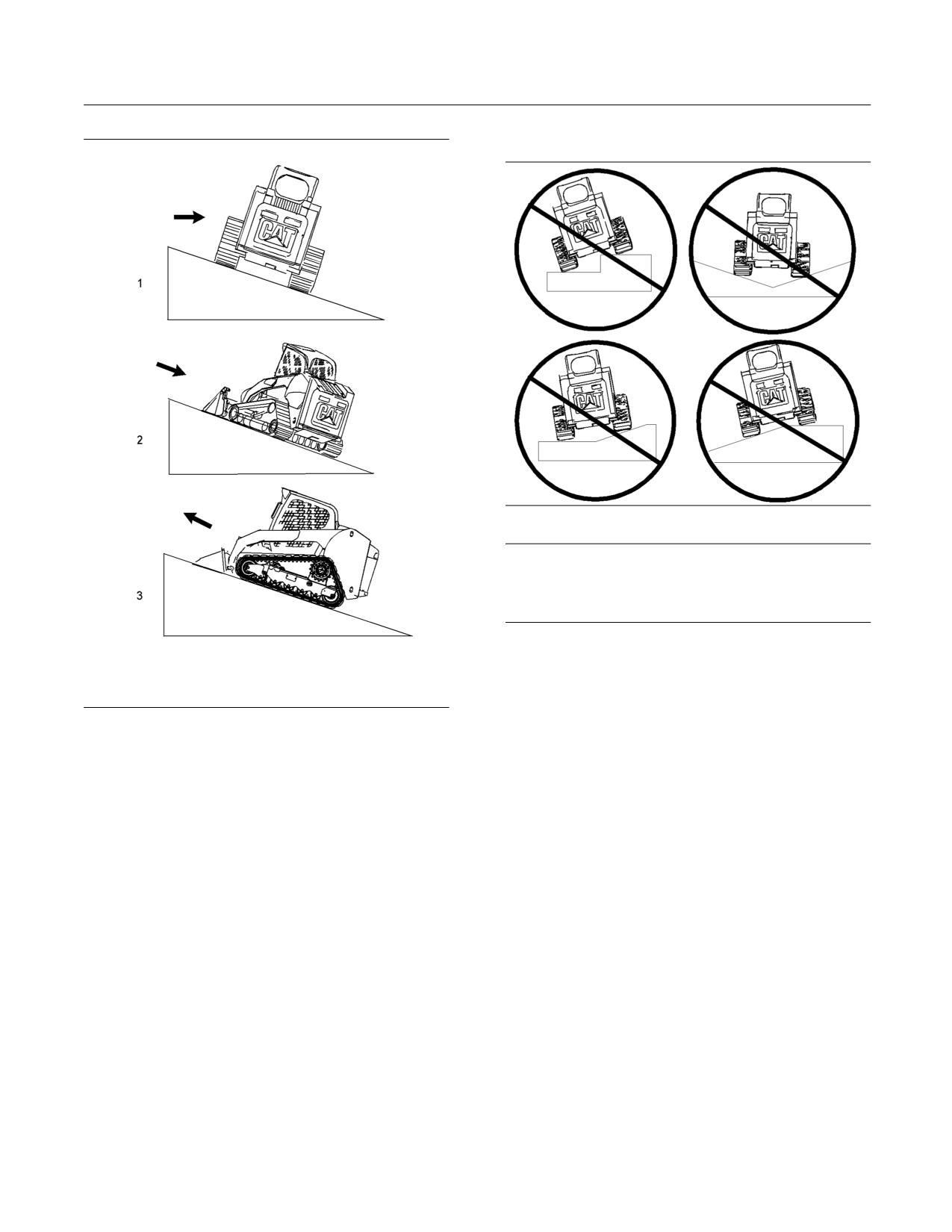
86
SEBU8407-06
Operation Section
Operation
Operating on a Transition
g01296038
Illustration 59
NOTICE
Avoid operating this machine on transitions. Operating
this machine on transitions may cause the tracks to
derail.
When the machine is operated on a transition, the
tracks may not be supported fully.
When the tracks are not supported fully, the wheels
g01451273
may ride on top of the drive lugs of the tracks.
Illustration 58
The track will derail if you continue to travel on the
1. Stop the machine. Turn the machine slowly while
transition.
you are backing down the slope.
If you must travel on a transition, travel the machine
Note: Do not back up a hill in order to turn.
at 90° to the transition. Do not perform hard turns or
fast turns when you are operating the machine on
2. Position the machine so that the front of the
the transition.
machine faces the direction for travel that is
desired.
Counterrotate turn
For maximum life of the undercarriage, use more
gradual turns while you slowly move forward or
reverse. Gradual turns will help minimize wear on the
track and wear on the wheels. Only use counterrotate
turns, if necessary. Sharp turns will increase the wear
on the components of the undercarriage.
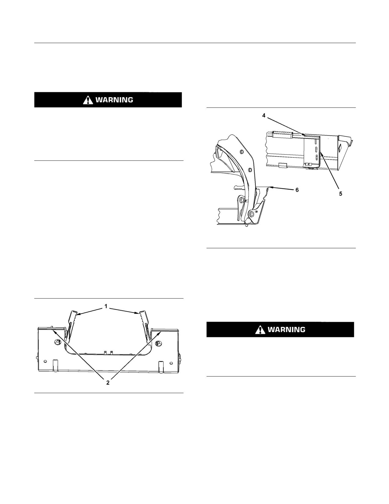
SEBU8407-06
87
Operation Section
Operation
i03708381
4. Fasten the seat belt and lower the armrests.
Work Tool Coupler Operation
5. Start the engine.
SMCS Code: 6129; 7000
6. Disengage the parking brake.
7. Tilt the quick coupler assembly forward.
Improper Attachment of the Work Tool could result
in injury or death.
Do not operate the machine without confirmation
that the coupler pins are fully engaged. Follow the
operating procedures in the Operation and Main-
tenance Manual.
Attaching the Work Tool
Note: Before you install the work tool, inspect the
coupler and the work tool mounting bracket for any
wear or for any damage. Ensure that the work tool
mounting bracket and the face of the coupler are
clean. Ensure that the coupler has no accumulation
of material. Refer to Operation and Maintenance
Manual, “Quick Coupler - Clean/Inspect” and
Operation and Maintenance Manual, “Work
Tool Mounting Bracket - Inspect” for inspection
procedures.
g01278223
Illustration 61
1. Position the work tool on a level surface. Move the
8. Align the quick coupler assembly (6) between the
hydraulic lines (if equipped) for the work tool and
outer plates (5) of the mounting bracket. Move the
electrical lines (if equipped) away from the work
quick coupler assembly under the angled plate (4)
tool mounting bracket.
of the mounting bracket and rack back the work
tool.
9. Fully lower the loader arms.
Improper attachment of the work tool could re-
sult in injury or death. If the work tool touches the
ground, the work tool may move away from the
coupler. Do not allow the work tool to touch the
ground until the coupler pins are fully engaged.
10. Turn the engine start switch key to the OFF
g01263431
position in order to stop the engine.
Illustration 60
11. If the work tool requires hydraulics, the hydraulic
2. If the machine is equipped with a manual coupler,
system pressure must be released before you
ensure that the levers(1) for the coupler are in
connect the work tool. Refer to the section
the DISENGAGED position. If the machine is
“Auxiliary Hydraulic Pressure Release”.
equipped with a hydraulic quick coupler refer to
Operation and Maintenance Manual, “Operator
12. Exit the machine.
Controls” for details on the location and the
operation of the hydraulic quick coupler control.
Note: If you are installing a material handling arm
that is not equipped with the optional center step,
3. Enter the machine.
do not exit the machine. A second person needs to
perform steps 13 through step 15.
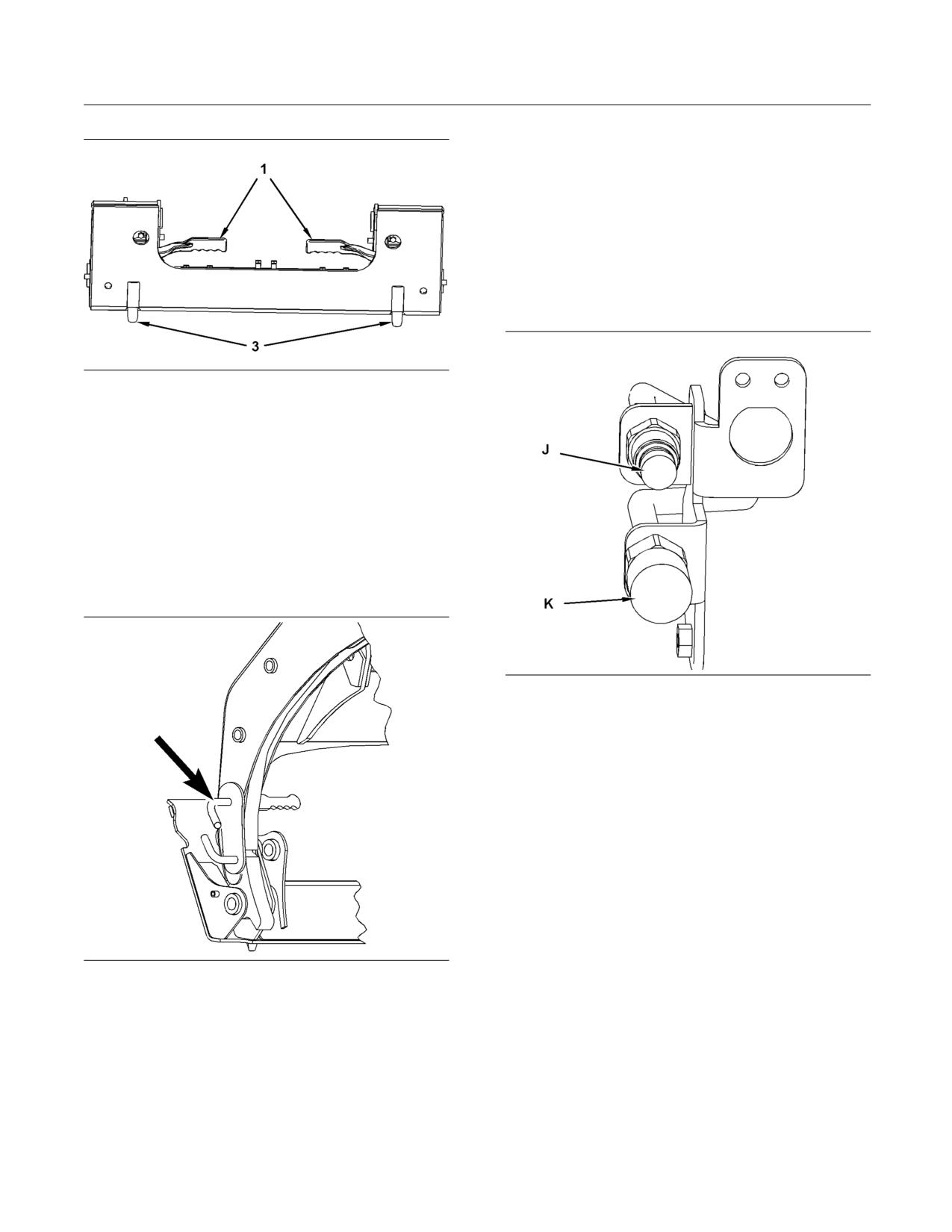
88
SEBU8407-06
Operation Section
Operation
b. Ensure that the quick connect couplers are
clean.
c. Connect the auxiliary hydraulic hoses for the
work tool to the machine. Twist the collar of the
quick connect coupler for one quarter of a turn
in order to secure the hydraulic connections.
If the work tool uses High Flow hydraulics,
refer to Operation and Maintenance Manual,
“Operator Controls - Auxiliary Hydraulic
Controls” for operating details.
g01263432
Illustration 62
13. Engage the coupler pins(3). If the machine is
equipped with a manual coupler, ensure that the
levers(1) for the coupler are in the ENGAGED
position. If the machine is equipped with a
hydraulic quick coupler refer to Operation and
Maintenance Manual, “Operator Controls” for
details on engaging the coupler pins.
14. If the work tool requires hydraulics, refer to
the following procedure in order to connect the
hydraulic hoses.
g01291620
Illustration 64
Standard Auxiliary Connection
g02020639
Illustration 63
a. Route the hydraulic hoses through the hose
guide on the machine in order to prevent
damage to the hoses. Not all work tools require
the hydraulic hoses to be routed through the
hose guide. The work tool Operation and
Maintenance Manual will inform you if the
hydraulic hoses need to be routed through the
hose guide. Caterpillar work tools require the
hoses to be routed through the hose guide.
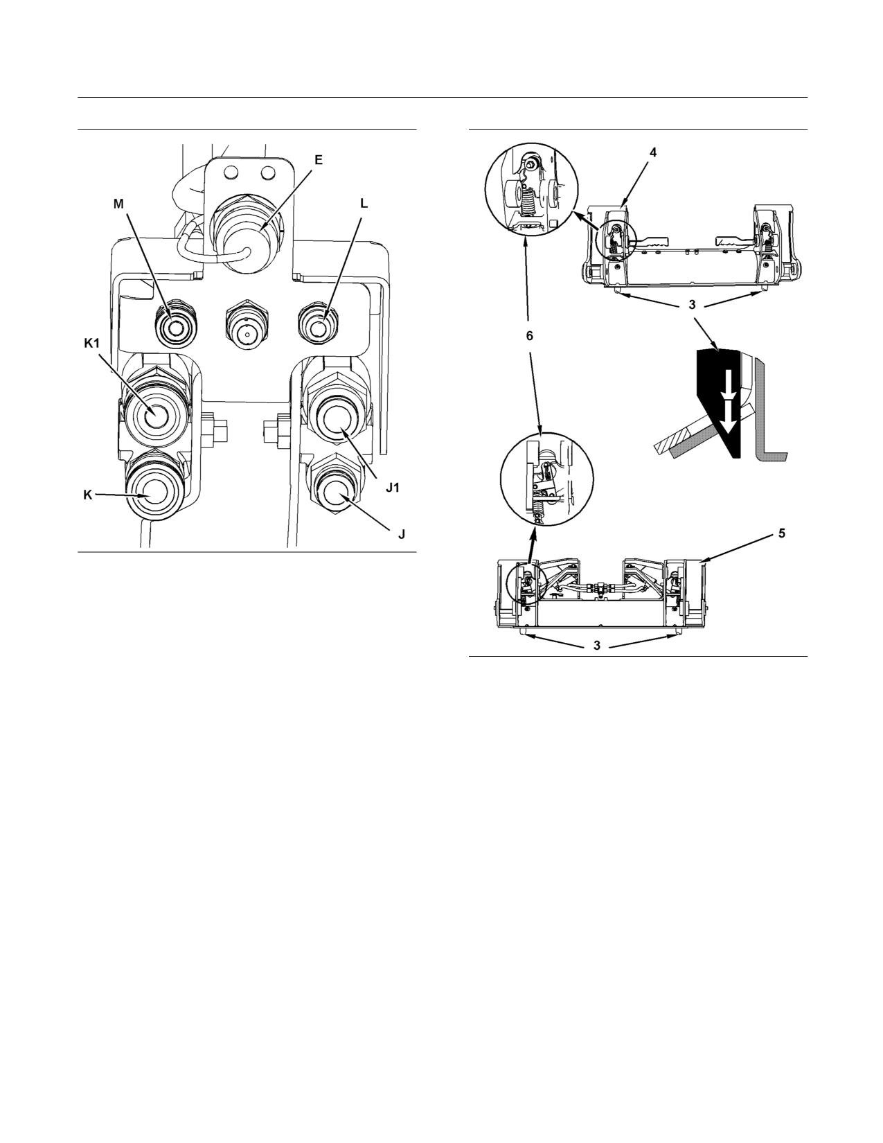
SEBU8407-06
89
Operation Section
Operation
g01210266
Illustration 65
High Flow Auxiliary Connection
d. If the work tool is equipped with electrical lines,
then route the electrical lines with the hydraulic
hoses and connect the wire harness to the
electrical connector (E) on the host machine.
g01352752
Illustration 66
Check the connections in order to ensure that
(3) Coupler Pins
the connections are properly secured. Check
(4) Manual Work Tool Coupler
the connections on the work tool in order to
(5) Hydraulic Work Tool Coupler
ensure that the connections are in the correct
(6) Lever for the Coupler Pin
receptacle.
15. Visually ensure that both coupler pins (3) are
Note: If your High Flow work tool does not have a
extending out of the holes in the work tool
wiring harness, a Jumper Plug needs to be installed
mounting bracket.
on the electrical plug for the work tool control. Without
this Jumper Plug, the machine will not provide high
16. Use the following procedure to verify engagement
flow to the work tool. Please refer to your Parts
of the coupler pins.
Manual for the current part number for the Jumper
Plug.
a. Enter the machine.
e. If the work tool is equipped with a water line,
b. Fasten the seat belt and lower the armrests.
then connect the water line from the work tool
to the connector on the machine. Move the
c. Start the engine.
water line to a position that is away from the
work tool mounting bracket.
d. Disengage the parking brake.
e. Raise the work tool off the ground.
f. Visually inspect the coupler pins (3) in order to
ensure that the pins are fully extended through
the work tool.
90
SEBU8407-06
Operation Section
Operation
g. Visually inspect the lever (6) that holds the
7. Disconnect the auxiliary hydraulic hoses from the
coupler pins in order to ensure that the lever is
machine.
in the proper position.
Note: If protective caps are available, install
h. Activate the tilt control in order to tilt the work
protective caps over the quick connect couplers.
tool downward.
8. If hoses are routed through the hose guide,
i. Apply down pressure on the work tool.
remove the hoses from the hose guide. Move the
hoses to a position that is away from the work tool
Note: The work tool Operation and Maintenance
mounting bracket.
Manual will inform you if forward pressure should not
be applied on a work tool.
Note: Connect the hoses for the work tool together.
Connecting the hoses together will reduce the
j. Move the machine backward. Ensure that the
probability of contaminating the hydraulic system.
coupler pins do not disengage from the work
Connecting the hoses together will reduce the
tool.
buildup of pressure in the hoses. Connecting the
hoses together will ease the connection of the hoses
17. Test the work tool for leaks and for proper
to the machine.
operation.
9. If the work tool is equipped with an electrical
line, then disconnect the wire harness from the
Removing the Work Tool
connector on the machine. If protective caps are
available, install protective caps over the electrical
connectors.
Disengaging the coupler pins will release the work
10. If the auxiliary electrical line is routed through the
tool from control of the operator.
hose guide, remove the line from the hose guide.
Move the auxiliary electrical line to a position that
Serious injury or death may result from disengag-
is away from the work tool mounting bracket.
ing the work tool when it is in an unstable position
or carrying a load.
11. If the work tool is equipped with a water line, then
disconnect the water line from the connector on
Place the work tool in a safe position before dis-
the machine. Move the water line to a position that
engaging the coupler pins.
is away from the work tool mounting bracket.
12. Exit the machine.
NOTICE
Auxiliary hoses for work tools must be disconnected
Note: If you are removing a material handling arm
before the quick coupler is disengaged.
that is not equipped with an optional center step,
do not exit the machine. A second person needs to
Pulling the work tool with the auxiliary hoses could
perform step 13.
result in damage to the host machine or the work tool.
13. Disengage the coupler pins. If the machine is
equipped with a manual coupler, ensure that the
1. Position the machine on level ground.
levers for the coupler are in the DISENGAGED
position. If the machine is equipped with a
2. Lower the work tool to the ground.
hydraulic quick coupler, refer to Operation and
Maintenance Manual, “Operator Controls” for
3. Rack back the work tool until the work tool is
details on disengaging the coupler pins with the
slightly off the ground.
hydraulic quick coupler control.
4. Turn the engine start switch key to the OFF
14. Enter the machine.
position in order to stop the engine.
15. Fasten the seat belt and lower the armrests.
5. If the work tool requires hydraulics the hydraulic
system pressure must be released. Refer to the
16. Start the engine.
section “Releasing the Auxiliary Hydraulic System
Pressure”.
17. Disengage the parking brake.
6. Perform Step 7 through Step 12 only after you
have released the hydraulic system pressure.
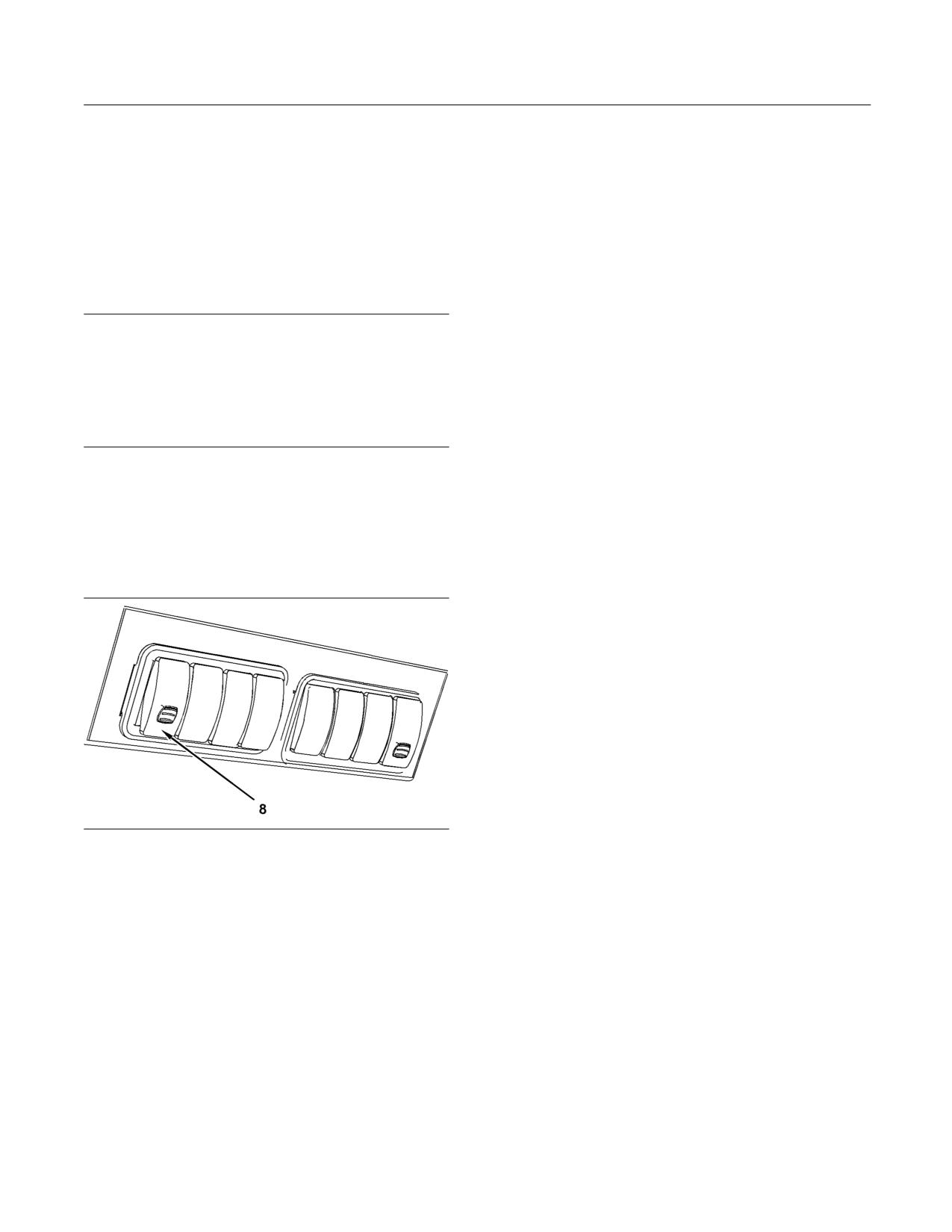
SEBU8407-06
91
Operation Section
Operation
18. As you slowly back away from the mounting
Note: The pressure in the secondary circuit is not
bracket, tilt the quick coupler assembly forward
affected by this switch.
until the top of the quick coupler assembly clears
the angled plate.
Note: The operator must remain in the seat with the
armrests in the LOWERED position in order for the
19. Back away from the work tool.
control to function. If equipped, the front door must
be closed.
Releasing the Auxiliary Hydraulic
3. Move the engine start switch to the OFF position.
System Pressure
Secondary Auxiliary Circuit
NOTICE
If the work tool is equipped with an Operation and
The pressure in the secondary circuit is released with
Maintenance Manual, follow the procedure that is de-
the following procedure:
scribed in the Operation and Maintenance Manual for
that work tool. Damage to the work tool and the host
If electrical power is available and the accumulator
machine may occur if you do not follow the proper in-
is charged, the pressure can be released from the
stallation procedure.
operator station with the work tool control.
1. Fasten the seat belt. Lower the armrests.
Refer to Operation and Maintenance Manual,
“Operator Controls - Auxiliary Hydraulic Pressure
2. Move the engine start switch to the ON position.
Release”.
Press the parking brake switch and release the
parking brake switch.
Standard Flow Auxiliary Circuit and the
Note: The parking brake indicator will remain
High Flow Auxiliary Circuit (if equipped)
illuminated since the engine is not running. When the
indicator for the work tool is no longer illuminated, the
pressure can be released.
3. Activate the controls for the secondary auxiliary
function. Activate the controls several times
in order to release all the pressure. Refer to
Operation and Maintenance Manual, “Operator
Controls - Auxiliary Hydraulic Controls” for
information about the controls.
If the pressure is not released, the accumulator is not
charged. It is possible to recharge the accumulator
by running the engine or cranking the engine for a
period of fifteen seconds. Repeat steps 2 and 3 in
g01274820
order to release the pressure.
Illustration 67
(8) Auxiliary Hydraulic Pressure Release
1. After the engine has run in order to charge
the accumulator, turn the ignition switch to the
OFF position. Turn the ignition switch to the ON
position. Press the parking brake switch and
release the parking brake switch.
Note: The parking brake indicator will remain
illuminated since the engine is not running. When the
indicator for the work tool is no longer illuminated, the
pressure can be released.
2. Push up on the locking tab and press the bottom
of the switch in order to release the pressure in the
Standard Flow Auxiliary Circuit and the High Flow
Auxiliary Circuit (if equipped). Hold the switch for
four seconds and release the switch.
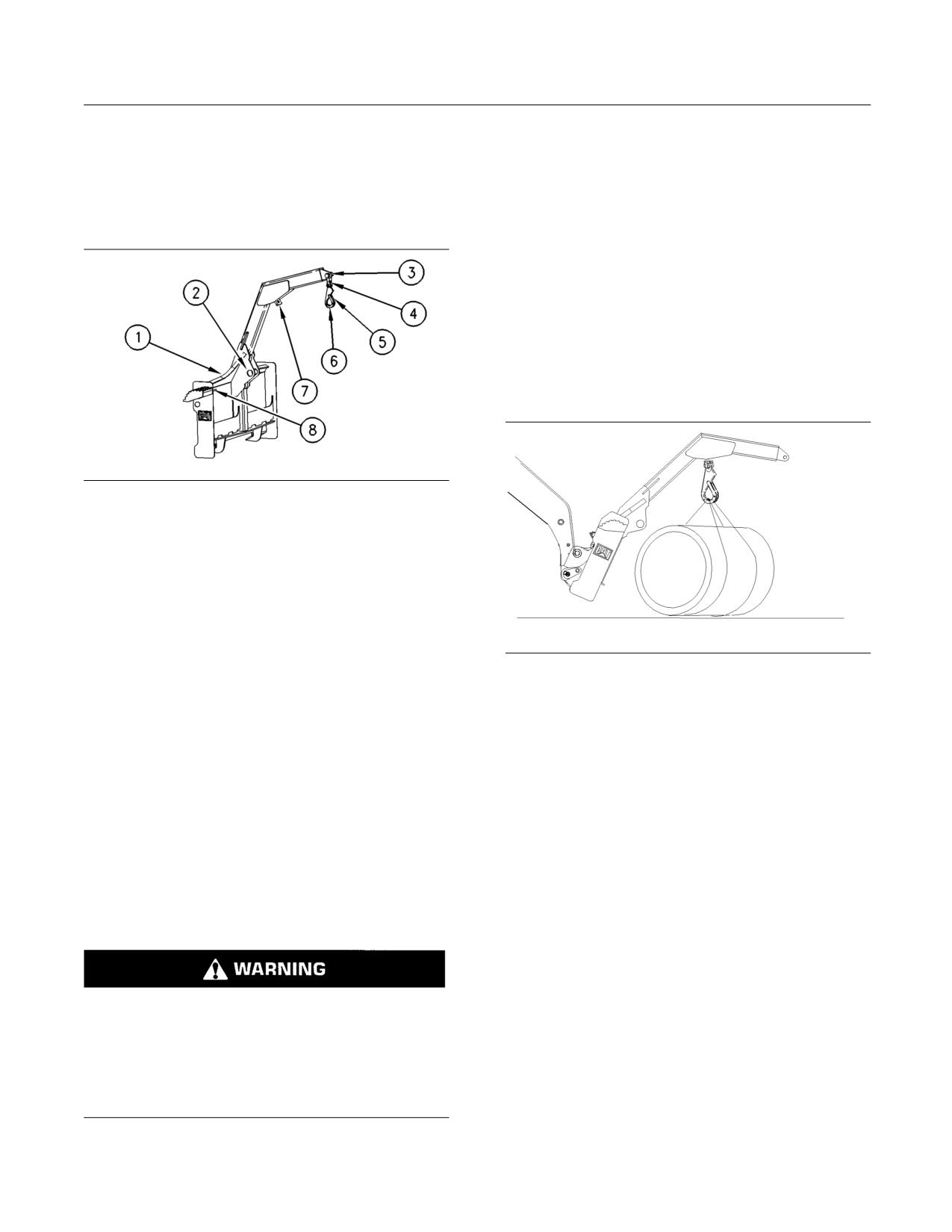
92
SEBU8407-06
Operation Section
Operation
i01964204
Two Person Operation
Material Handling Arm
Attaching A Load
Operation
1. Verify that the load does not exceed the weight
SMCS Code: 6400; 6700; 7000
limit. Refer to the Operation and Maintenance
Manual, “Material Handling Arm Rated Load” for
the rated load capacities.
2. Keep all personnel out of the work area at all
times, except when you are attaching or removing
a load.
3. Enter the machine. Start the engine.
4. Disengage the parking brake.
g00674640
Illustration 68
(1) Location of Optional Center Step
(2) Tie-Down Point
(3) Lifting Point 2
(4) Shackle
(5) Hook Clasp
(6) Hook
(7) Lifting Point 1
(8) Stored location of Position Lock Pin
Inspect the material handling arm and the
attachments for wear and damage. Ensure that the
g01020534
Illustration 69
load is properly attached to the material handling arm
before you operate the machine.
5. Keep the loader arms in the fully lowered position.
Slowly position the material handling arm until
Note: The physical size and the weight of the load
either lifting point 1 or the lifting point 2 is directly
determines the lifting point that is appropriate.
above the load.
Whenever it is possible, use the lifting point 1. This
will improve the stability and this will reduce the
6. Tilt the material handling arm forward until the
movement of the load. Refer to the Operation and
hook is slightly higher than the load in order to
Maintenance Manual, “Material Handling Arm Rated
minimize swinging of the load.
Load” for the limitations on the weight.
7. Stop the engine.
Note: Use only Caterpillar 9V-2714 Hook and
Caterpillar 9V-2715 Shackle to attach a load to the
8. Wait as the second person attaches the load
material handling arm. Never use an open hook. Use
securely to the hook. The second person needs
a line that is rated for 2.5 times the weight of the load.
to ensure that the hook clasp is in the locked
position.
9. Ensure that ALL personnel have left the work area.
Do not allow anyone to be near a suspended load
10. Start the engine.
unless the position lock pin is installed. If the lift
arms must be raised to handle a tall load, do not
11. Disengage the parking brake.
allow anyone to be near the suspended load un-
less the lift arms are blocked. Failure to follow the
12. Slowly tilt back the material handling arm until the
instructions or heed the warnings could result in
material handling arm is fully tilted back.
injury or death.
13. Stop the engine.
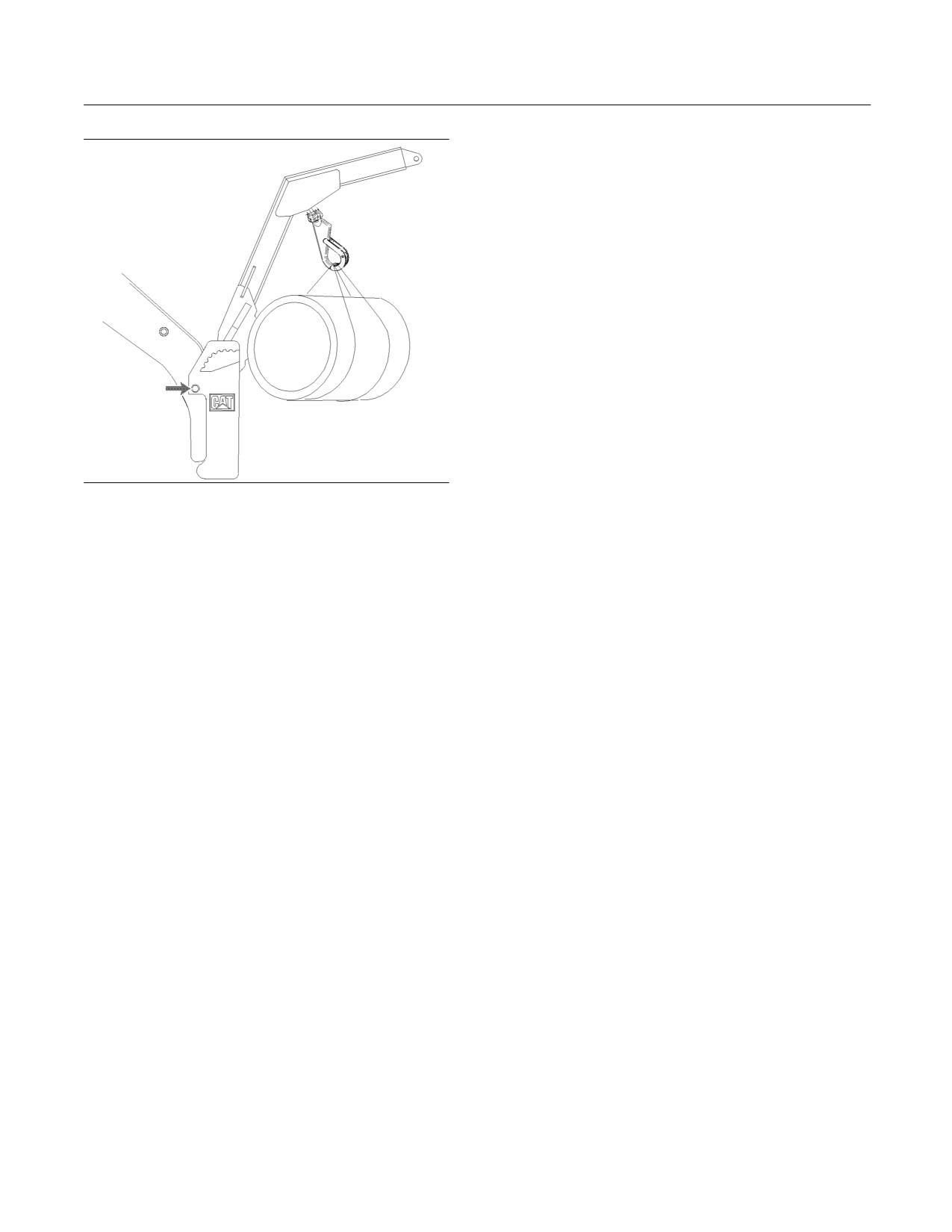
SEBU8407-06
93
Operation Section
Operation
5. Wait as the second person removes the position
lock pin. Wait as the second person places the pin
in the STORED position on the material handling
arm.
6. Remove all personnel from the work area.
7. Start the engine.
8. Disengage the parking brake.
9. Lower the load to the ground.
10. Stop the engine.
11. Wait as the second person removes the load from
the hook.
12. Remove all personnel from the work area.
13. Start the engine.
g01020535
Illustration 70
14. Disengage the parking brake.
14. Wait as the second person installs the position
15. Slowly tilt back the material handling arm until the
lock pin through the hole in the material handling
material handling arm is fully tilted back.
arm and the hole in the loader arm of the machine.
16. Back away from the load.
Note: This will prevent the material handling arm
from tilting forward.
One Person Operation
15. Wait as the second person secures the load to
the tie-down points with a suitable line in order
Note: The material handling arm must be equipped
to minimize load swing.
with a center step in order to do the one person
operation.
Note: Do not move the load when you are securing
the load. Do not pull the load toward the material
Attaching the Load
handling arm when you are securing the load to the
tie-down points.
1. Verify that the load does not exceed the weight
limit. Refer to the Operation and Maintenance
16. Wait as the second person removes the position
Manual, “Material Handling Arm Rated Load” for
lock pin. Wait as the second person places the pin
the rated load capacities.
in the STORED position on the material handling
arm.
2. Keep all personnel out of the work area at all
times, except when you are attaching or removing
Removing a Load
a load.
1. Slowly tilt back the material handling arm until the
3. Enter the machine. Start the engine.
material handling arm is fully tilted back. Lower
the loader arms fully.
4. Disengage the parking brake.
2. Stop the engine.
3. Wait as the second person installs the position
lock pin through the hole in the material handling
arm and the hole in the loader arm of the machine.
4. Wait as the second person removes the line that
secures the load to the tie-down points.
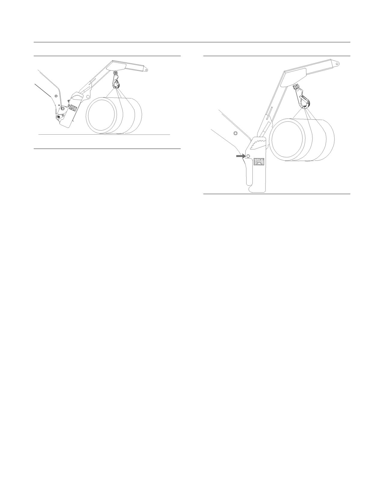
94
SEBU8407-06
Operation Section
Operation
g01020534
Illustration 71
5. Keep the loader arms in the fully lowered position.
Slowly position the material handling arm until
either lifting point 1 or lifting point 2 is directly
above the load.
g01020535
Illustration 72
6. Tilt the material handling arm forward until the
hook is slightly higher than the load in order to
14. Install the position lock pin through the hole in the
minimize swinging of the load.
material handling arm and the hole in the loader
arm of the machine.
7. Stop the engine. Exit the machine.
15. Secure the load to the tie-down points with a
8. Attach the load securely to the hook. Ensure that
suitable line in order to minimize load swing.
the hook clasp is in the LOCKED position.
Note: Do not move the load when you are securing
9. Keep all personnel out of the work area.
the load. Do not pull the load toward the material
handling arm when you are securing the load to the
10. Enter the machine. Start the engine.
tie-down points.
11. Disengage the parking brake.
16. Remove the position lock pin and place the pin
in the STORED position on the material handling
12. Slowly tilt back the material handling arm until the
arm.
material handling arm is fully tilted back.
13. Stop the engine. Exit the machine.
Removing a Load
1. Fully tilt back the material handling arm. Fully
lower the loader arms.
2. Stop the engine. Exit the machine.
3. Install the position lock pin through the hole in the
loader arm of the machine.
4. Remove the line that secures the load to the
tie-down points .
5. Remove the position lock pin and place the pin
in the STORED position on the material handling
arm.
6. Keep all personnel out of the work area.
7. Enter the machine. Start the engine.
8. Disengage the parking brake.
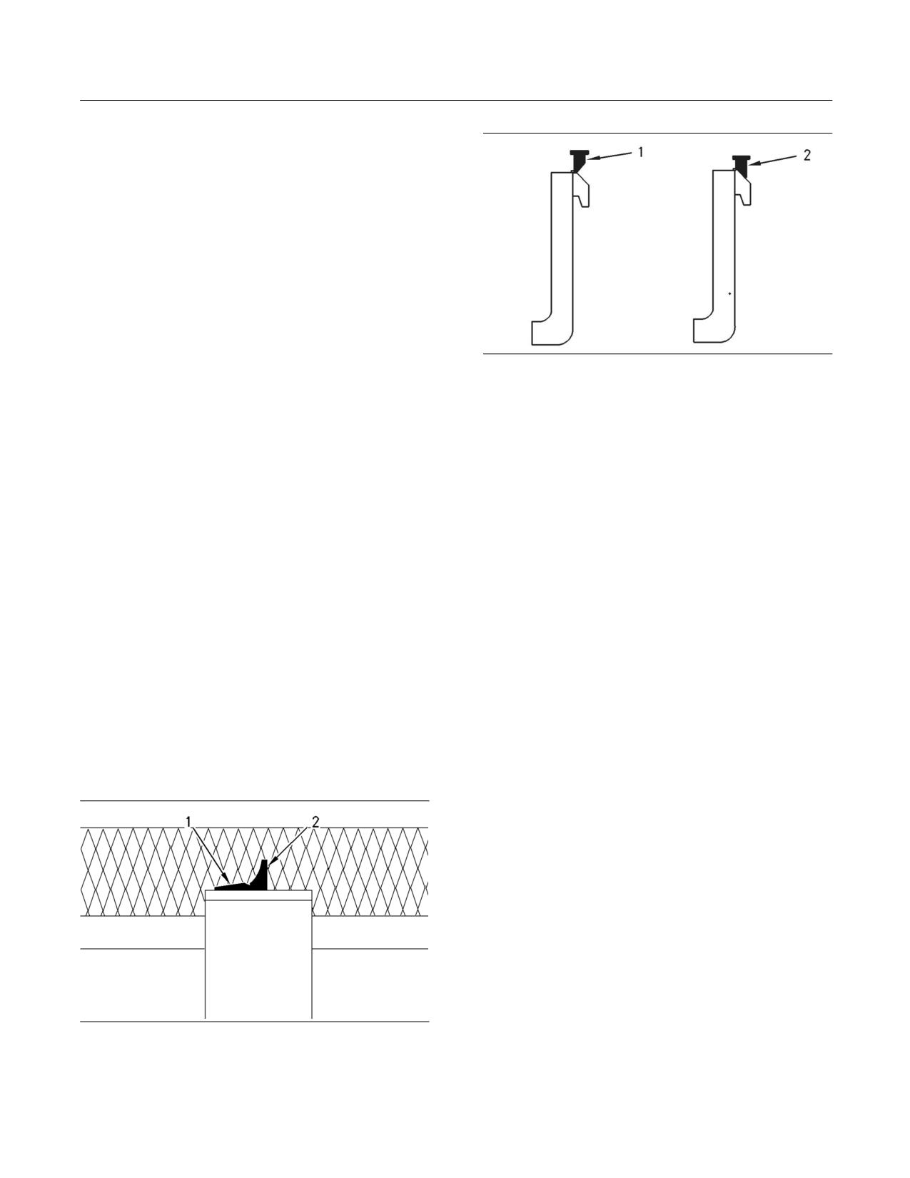
SEBU8407-06
95
Operation Section
Operation
9. Lower the load to the ground.
10. Stop the engine. Exit the machine.
Note: Make sure that the load is stable.
11. Remove the load from the hook.
12. Keep all personnel out of the work area.
13. Enter the machine. Start the engine.
14. Disengage the parking brake.
15. Slowly tilt back the material handling arm until the
g00955964
Illustration 74
material handling arm is fully tilted back.
The “type 2” pin that is in the unlocked position (1) and the locked
position (2).
16. Back away from the load.
1. Put the fork tines in the Unlocked position. Space
Traveling with a Load
the fork tines as far as possible from each other.
1. Ensure that all personnel have left the work area.
2. Put the fork tines in the Locked position.
2. Start the engine.
3. Slowly, move the machine into position and
engage the load. The machine should be square
3. Disengage the parking brake.
with the load. Space the forks evenly between the
pallet stringers.
4. Raise the load so that the load is slightly off of the
ground.
4. Move the machine forward until the load contacts
the carriage.
5. Slowly travel to the destination. Keep the load as
close to the ground as possible. Travel up slopes
5. Lift the load carefully.
with the load uphill. Travel down slopes with the
load uphill. Do not travel across slopes.
6. Slowly, move the machine in reverse until the load
is clear enough to lower.
i01878348
7. Carefully lower the load while you tilt the forks
Pallet Forks Operation
back to the travel position.
SMCS Code: 6700; 7000
Travel with the load as low as possible while you still
maintain ground clearance.
Travel with the load uphill on upgrades and on
downgrades.
g00955937
Illustration 73
The “type 1” pin that is in the unlocked position (2) and the locked
position (1).
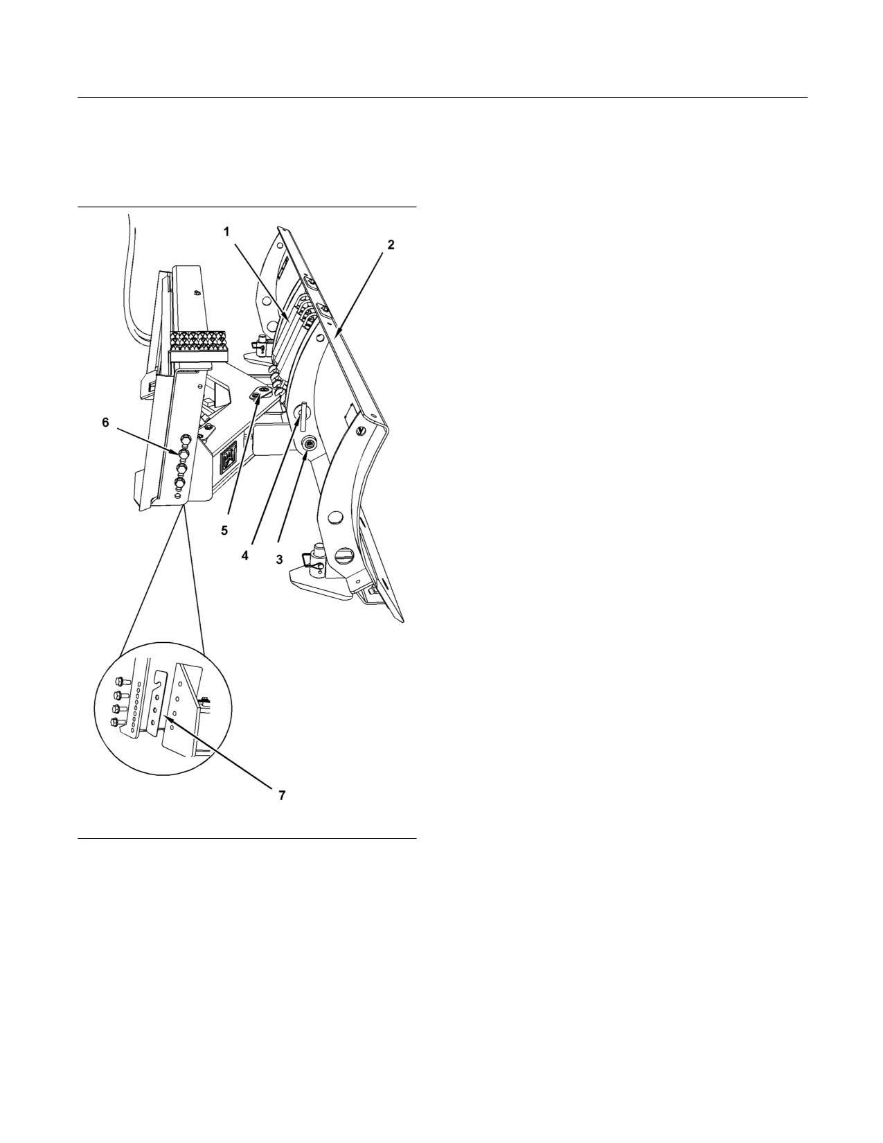
96
SEBU8407-06
Operation Section
Operation
i02955359
2. Position the blade so that the vertical pivot pin (5)
is in the vertical position.
Angle Blade Operation
3. Move the angle of the blade fully from one side
SMCS Code: 6060; 7000
to the other side. The blade cutting edge should
remain parallel to the ground.
4. If the blade cutting edge does not remain parallel
to the ground, the height of the blade needs to
be adjusted. Use the following steps in order to
adjust the height:
a. Lower the blade and the frame onto adjustable
stands.
b. Stop the engine and remove the ignition key.
c. Remove the bolts (6) for adjusting the height.
d. Move the frame to the desired height.
e. Ensure that the shims are installed. Install the
bolts for adjusting the height. Tighten the bolts
to a torque of 270 ± 40 N·m (199 ± 30 lb ft).
f. In order to test the adjustment, start the engine.
g. Repeat steps 2 and 3.
Tilt Lock
The angle blade has two modes of operation:
• Locked
• Spring load trip
In order to lock the blade, install the locking pin (4). In
the locked position, the blade can be used for heavy
operations. The blade will not tilt with the locking pin
in the locked position.
There may be lighter operations that allow the blade
to tilt. Remove the locking pin and store the locking
pin in the cab. This will help prevent damage to the
g01470952
blade or to the frame. If the plowing overcomes
Illustration 75
306 kg (675 lb) of spring force, the top of the blade
(1) Springs
will tilt forward.
(2) Blade
(3) Pivot pin for the blade
(4) Locking pin
i04000738
(5) Vertical pivot pin
(6) Bolts for adjusting height
(7) Shims
Work Tool Operation
SMCS Code: 6700; 7000
Height Adjustment
The following table describes the functionality of
In order to properly adjust the height of the blade,
approved Caterpillar work tools.
use the following procedure:
1. Start the engine.
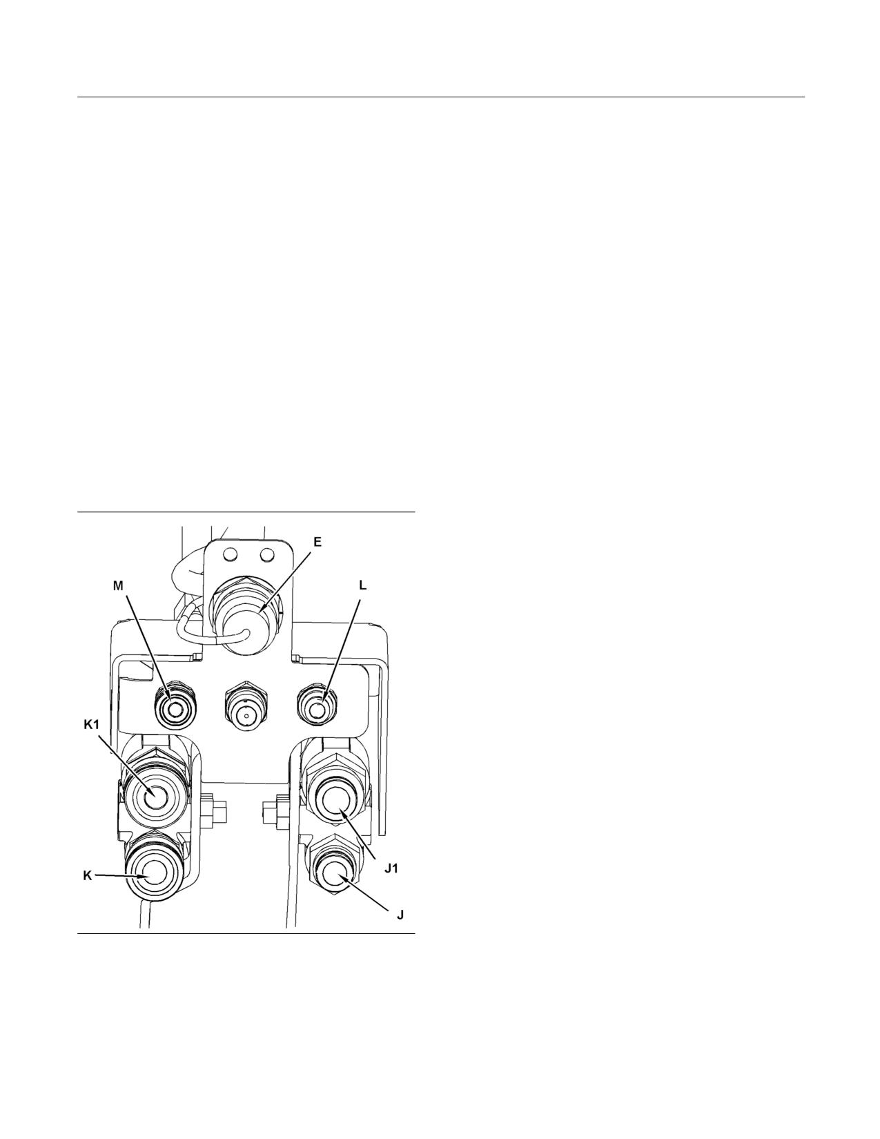
SEBU8407-06
97
Operation Section
Operation
Refer to Operation and Maintenance Manual,
Note: If your High Flow work tool does not have
“Operator Controls - Joystick Controls” and Operation
a wiring harness, a Jumper Plug (241-3763 Plug
and Maintenance Manual, “Operator Controls -
As) should be installed on the electrical plug (1) for
Auxiliary Hydraulic Controls” for the location and
the work tool control. Without this Jumper Plug, the
operation of the joystick controls that are referenced
machine will not provide High Flow to the work tool.
below.
The affected machines are in the following list:
Note: All of the work tool functions that are described
Simple Hydromechanical Work
below are viewed from the left side of the machine.
Tools
Operate the machine and the work tool slowly in an
open area. Check for proper operation of all controls
Work tools in the following table are approved by
and all protective devices on the machine and the
Caterpillar. Refer to Operation and Maintenance
work tool.
Manual, “Operator Controls - Joystick Controls”
and Operation and Maintenance Manual, “Operator
Note: During initial operation, unexpected motion
Controls - Auxiliary Hydraulic Controls” for the
may occur due to air in the hydraulic system. Cycle
location and operation of the joystick controls that are
the hydraulic system approximately five times in
referenced in the table.
order to purge air out of the circuit. You may need to
add hydraulic oil to the machine after the machine
Please read the manual and understand the
fills the hydraulic circuits of the work tool. Refer
instructions and warnings in the Operation and
to Operation and Maintenance Manual, “Hydraulic
Maintenance Manual for these work tools. Consult
System Oil Level - Check” for the proper procedure
your Caterpillar dealer for replacement manuals.
for checking the hydraulic oil level.
Proper care is your responsibility.
g01210266
Illustration 76
For all High Flow work tools, refer to Operation and
Maintenance Manual, “Operator Controls - Joystick
Controls”. Connect the wiring harness to the electrical
plug (E).

98
SEBU8407-06
Operation Section
Operation
Table 23
Operation of Caterpillar Simple Hydromechanical Work Tools
Work Tool
Left Hand Joystick
Right Hand Joystick
Actions
8
5
6
7
1
2
3
4
Multipurpose
X
The bucket clam closes.
Bucket
X
The bucket clam opens.
All Grapple Tools
X
The grapple closes.
X
The grapple opens.
Angle Blade
X
The blade angles to the left.
X
The blade angles to the right.
Dozer Blade
X
The blade angles to the left.
X
The blade angles to the right.
X
X
The blade tilts down to the left.
X
X
The blade tilts down to the right.
X
X
The blade tilts down to the left and the blade
angles to the left.
X
X
The blade tilts down to the right and the blade
angles to the right.
Complex Hydromechanical Work
Tools
Note: For the functionality of Caterpillar Complex
Work Tools, please read the Operation and
Maintenance Manual for the work tool.
Consult your Caterpillar dealer for replacement
manuals. Please read all the safety messages and
understand all the safety messages for each work
tool.
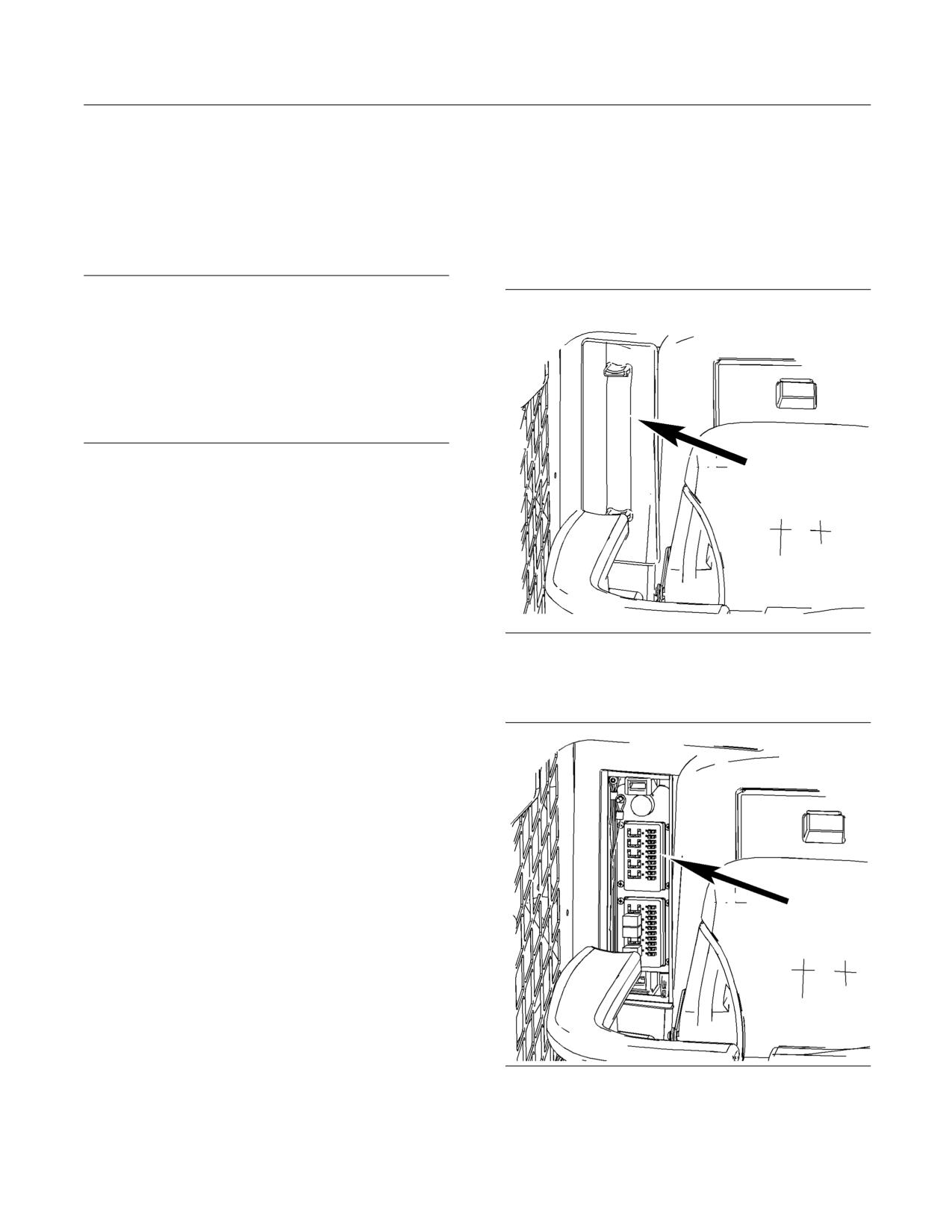
SEBU8407-06
99
Operation Section
Parking
i02417403
Parking
Stopping the Engine if an
i02582658
Electrical Malfunction Occurs
Stopping the Engine
SMCS Code: 1000; 7000
SMCS Code: 1000; 7000
Inside Cab
NOTICE
Stopping the engine immediately after it has been
working under load, can result in overheating and ac-
celerated wear of the engine components.
Refer to the following procedure, to allow the engine
to cool, and to prevent excessive temperatures in the
turbocharger housing (if equipped), which could cause
oil coking problems.
1. Operate the engine for five minutes at low idle
with no load.
Note: This allows hot areas in the engine to cool
gradually. This will extend the engine life.
2. Move the joysticks to the NEUTRAL position.
3. Turn the engine start switch key to the OFF
position.
g01287527
Illustration 77
4. Relieve the pressure in the auxiliary hydraulic
system. Refer to Operation and Maintenance
The fuse panel is located behind the seat on the right
Manual, “Work Tool Coupler Operation” for details.
side.
5. Ensure that the engine start switch key is in the
OFF position after the pressure in the auxiliary
hydraulic system has been relieved.
6. Cover the exhaust opening after the machine has
cooled down.
g01210555
Illustration 78
Remove the cover in order to access the fuse panel.
//////////////////////////////////////////