Galeo HD785-7 DUMP TRUCK. Operation and Maintenance Manual (2006) - page 11
 

  Index      Manuals     Galeo HD785-7 DUMP TRUCK. Operation and Maintenance Manual (2006)


Search            copyright infringement  


Content      ..     9      10      11     


Galeo HD785-7 DUMP TRUCK. Operation and Maintenance Manual (2006) - page 11


ATTACHMENTS, OPTIONS

HANDLING PAYLOAD METER (VHMS BUILT-IN TYPE)

DATA STORED IN PAYLOAD METER

The payload meter takes the cycle from one dumping operation to the next dumping operation as one cycle and
records the data.
Cycle data items

Date (month/day) of
dumping

Time of traveling empty

Time remaining
stationary when loading

Time remaining
stationary when loaded

Time of dumping

Distance traveled empty

Time traveling loaded

Time taken to dump

Machine ID

Travel speed when empty
(max.)

Distance traveled loaded  Speed limit

Open ID

Travel speed when empty
(ave.)

Travel speed when
loaded (max.) 

Warning items for each
cycle

Payload

Time remaining
stationary when empty

Travel speed when
loaded (ave.)

The maximum limit for stored cycle data is 2900 cycles.  If 2900 cycles is exceeded, the old data is overwritten.
Download the recorded data using the RS232C port of a personal computer which has the separately sold special
software installed.
The downloaded data is saved in the specified location on the personal computer as a text file (CSV file).  For
details, see the instruction manual for the special software.
It is possible to check the downloaded data with a commercially available spreadsheet software that can read text
files.

PROCEDURE WHEN DOWNLOADING

 CAUTION

When handling the cables, be careful not to damage them or pull them by force.
Do not leave the connectors disconnected.
Take steps to prevent dirt from entering the connector portion.
Do not let any metal objects touch the connector portion.

Download the recorded data to a personal computer which has the separately sold special software installed.

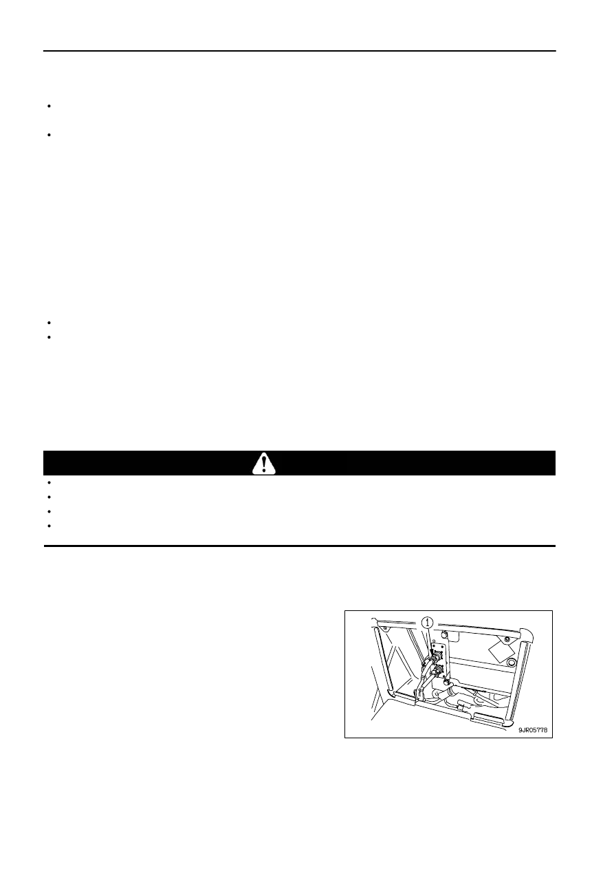
DOWNLOADING FROM DOWNLOAD CONNECTOR INSIDE CAB (REAR OF ASSISTANT'S SEAT)

 1. Remove connector (1) at the end marked PLM, and connect

the download cable supplied with the special software.
Connect the other end of the cable to the RS232C port of the
personal computer.

 2. Turn the starting switch to the ON position.

 3. Start up the personal computer and use the special software to download the data.

The download software for the HD785-3 card type payload meter can be used as it is for the special software.

 4. After completing the download operation, always return the cables to their original position.

6 - 22

ATTACHMENTS, OPTIONS

HANDLING PAYLOAD METER (VHMS BUILT-IN TYPE)

DOWNLOADING FROM GROUND LEVEL DOWNLOAD BOX OUTSIDE CAB

 WARNING

When downloading from outside the cab, check that the machine starting switch is at the OFF position.  In addition, be careful that
the starting switch inside the cab is not turned to the ON position during the download operation.  During the download operation,
pay careful attention to the machine and the surrounding area.

 1. Turn the starting switch to the OFF position.
 2. Open the ground level download box.  Use the starting switch key to open or close the box.
 3. Set switch (1) inside the box to the ON position.  After a short

time, display lamps (2) will light up.

 4. Connect the download cable supplied with the special software

to the end marked PLM, Connect the other end of the cable to
the RS232C port of the personal computer.

 5. Start up the personal computer and use the special software to

download the data.  For details of the download operation, see
"DOWNLOADING

FROM

DOWNLOAD

CONNECTOR

INSIDE CAB (REAR OF ASSISTANT'S SEAT) (PAGE 6-22)".

 6. After completing the download operation, return the switch inside the box to the OFF position, then close the box

securely.

6 - 23

ATTACHMENTS, OPTIONS

HANDLING PAYLOAD METER (VHMS BUILT-IN TYPE)

DOWNLOAD SOFTWARE

For details of installing the software, see the instruction manual provided with the download software.

 1. When the installation is completed, the icon shown in the

diagram on the right is created.

 2. Double click the icon.  The download software is started and

the screen shown in the diagram on the right is displayed.  After
that, screen [G1000] is displayed, so click [PLM].
[CARD] and [PMC] are not used, so do not click them.

 3. Click [Parameter Setting] on screen [G2000].

[PLM Remote Control] is not used, so do not click it.

6 - 24

ATTACHMENTS, OPTIONS

HANDLING PAYLOAD METER (VHMS BUILT-IN TYPE)

ATTACHMENTS, OPTIONS

HANDLING PAYLOAD METER (VHMS BUILT-IN TYPE)

 4. Click [Unit Setting] on screen [G2200].   Screen [G2210] is

displayed.
[User's Comment] is not used, so do not click it.

 5. On screen [G2210] it is possible to select the communication port (Com1, Com2), specify the destination for

saving the downloaded data, specify the file name, and select the unit for the data.   For details, see the
instruction manual for the download software.
The files used for the HD785-7 is the files for the summary and cycle data only, so put a check mark against
[Summary Data File] and [Cycle Data File] in [File]. Once the setting is mode, there is no need to make any
setting when the next download is carried out.
Click [Enter] to return to screen [G2200].

 6. On screen [G2200], click [BACK] to return to screen [G2000].
 7. Click [Download] on screen [G2000].   Screen [G2100] is

displayed, so click [START] to download.
After completing the download operation, click the [X] at the top
right of the screen to close the screen.

REMARK

Depending on the version of the software, screen [G2101
<Download - File ID>] is displayed.  Input the file ID, then click [OK]
to start the download operation.

6 - 25

ATTACHMENTS, OPTIONS

HANDLING PAYLOAD METER (VHMS BUILT-IN TYPE)

MACHINE ID, OPEN ID

It is possible to change the machine ID and open ID, which are cycle data items.  When changing the machine Serial
No. for the machine ID or the operator or type of load for the open ID, set the value specified by the customer
beforehand to make it possible to use to check the operator and type of load for the applicable cycle afterwards.

METHOD OF SETTING MACHINE ID, OPEN ID

 1. When the service meter/odometer is being displayed on the character display of the machine monitor, press the

(

"

) of machine monitor selector switch 1 to display reverse travel.

For details, see "OTHER FUNCTIONS OF MACHINE MONITOR (PAGE 3-27)".

 2. Press the (>) of machine monitor selector switch 2 several

times to display "PLM".

 3. Press the (

"

) of machine monitor selector switch 1 to display

"CALIBRATION".

 4. Press the (>) of machine monitor selector switch 2 to display

the screen shown in the diagram on the right.
ID1 corresponds to the machine ID.
The present setting is displayed on the bottom line.

6 - 26

ATTACHMENTS, OPTIONS

HANDLING PAYLOAD METER (VHMS BUILT-IN TYPE)

ATTACHMENTS, OPTIONS

HANDLING PAYLOAD METER (VHMS BUILT-IN TYPE)

 5. Press the (

"

) of machine monitor selector switch 1 to display

the screen shown in the diagram on the right.
The available settings range from 0 to 200; input in order from
the first digit.  The place for insertion is marked by the cursor.
Press the (<) or (>) of machine monitor selector switch 2 to
select 0 to 9.   After inputting the value, press the (

"

) of

machine monitor selector switch 1.  The cursor will move to the
next position.  
Repeat this procedure to input the values for all the digits, then
confirm the settings and return to the previous screen.

If the (

!

) of machine monitor mode selector switch 1 is pressed

while inputting any value, the value will stay as it is and the
cursor will move to the first digit.  If any mistake is made in the
input, input again from the first digit.
To abandon the input operation, press the (

!

) of machine

monitor mode selector switch 1 again and return to the
previous screen.

 6. When setting the open ID, press the (>) of machine monitor

selector switch 2 at Step 4 to display the screen shown in the
diagram on the right.
The procedure for setting is the same as for ID1 (machine ID).

 7. Press the (

!

) of machine monitor selector switch 1 several times to return to the service meter/odometer display.

6 - 27

ATTACHMENTS, OPTIONS

HANDLING PAYLOAD METER (VHMS BUILT-IN TYPE)

PAYLOAD (CYCLE DATA ITEM)

The payload measurements, which are recorded as data, apply to the haul payload in the applicable cycle.
The method for confirming the payload is to carry out processing of the total data sampled during travel from the
loading point to the dumping point.  These data are then saved.
The payload displayed on the machine monitor is the value before the above data-processing. It is possible that
the accuracy may become poor due to the weight of the machine while the data are being saved.
Use the display value on the machine monitor as a guideline.

SERVICE FUNCTIONS

The following functions are available, but for normal use, there is no need to make any change.  If it is necessary
to change the setting, please consult your Komatsu distributor.

 1. Setting travel distance needed to recognize completion of loading

The payload meter is set to judge that the loading is completed when the machine has traveled 160 m (524 ft
11 in) continuously from the loading point.  If the dumping point is within 160 m (524 ft 11 in) from the loading
point, the system will not judge that dumping has taken place, so the cycle data at that point will be incomplete.
In cases where the loading point and the dumping point are extremely close, use this function to change to the
setting for the travel distance needed to recognize the completion of loading.

OTHERS

If it is necessary to correct the data or time during the download operation, please consult your Komatsu
distributor.
If the payload and external display lamp display is different, or there is some error in the directory where the data
is downloaded by the special software, there may be a mistake in the setting for the machine.
In such a case, please consult your Komatsu distributor.
Use a serial communication port (RS232C) to download the data.
For computers without an RS232C port, it may be possible to use a third party USB-RS232C conversion adapter.
(Part for operation check: IO DATA USB-RSAQ2)
However, this does not guarantee the operation.  In addition, the download software supports COM1 and COM2,
so check which port it can be connected to.

6 - 28

ATTACHMENTS, OPTIONS

HANDLING DUMPING COUNTER

HANDLING DUMPING COUNTER

The dumping counter is an automatic counting function to count
the number of loads that have been dumped.
The number of loads dumped is displayed on the character
display.

METHOD OF DISPLAYING, RESETTING DUMPING COUNTER

 1. Check that the character display is showing the service meter/odometer, or the action code.  If it is giving any

other display, turn the starting switch OFF, then turn the starting switch to the ON position and wait for the above
display to be given.

 2. Press (

"

) of machine monitor mode selector switch 1. The

character display shows the dumping counter.

 3. When resetting the number of loads dumped, press (

"

) of

machine monitor mode selector switch 1. The display shows
the screen on the right.

 4. Press (

"

) of machine monitor mode selector switch 1. The

number of loads dumped is reset and the display returns to the
previous screen.
To abandon the resetting operation, press (

!

) of machine

monitor mode selector switch 1 to return to the previous
screen.

 5. When completing the operation, press (

!

) of machine monitor

mode selector switch 1 or turn the starting switch  OFF.

6 - 29

INDEX

INDEX

<A>
AIR CONDITIONER

3- 66

<B>
BEFORE READING THIS MANUAL

1-

2

BODY PIVOT PIN

3- 46

BREAKING-IN THE MACHINE

3- 99

<C>
CAR RADIO

3- 51

CAR STEREO

3- 57

CHECK BEFORE STARTING ENGINE

3- 74

CHECKS AFTER COMPLETION OF
WORK

3-127

CHECKS AFTER STOPPING ENGINE

3-100

COLD WEATHER OPERATION

3-136

    AFTER COLD WEATHER

3-138

    PRECAUTIONS AFTER
    COMPLETION OF WORK

3-137

    PRECAUTIONS FOR LOW
    TEMPERATURE

3-136

CONTROL LEVERS AND PEDALS

3- 41

<D>
DETERMINING AND MAINTAINING
TRAVEL ROAD

3-131

    DETERMINING TRAVEL ROAD

3-131

    MAINTAINING TRAVEL ROAD

3-131

DUMP OPERATIONS

3-123

DUST INDICATOR

3- 47

<E>
EXPLANATION OF COMPONENTS

3-

5

<F>
FUSES

3- 48

<G>
GENERAL VIEW

3-

2

GENERAL VIEW OF CONTROLS AND
GAUGES

3-

3

GENERAL VIEW OF MACHINE

3-

2

GUIDES TO MAINTENANCE

4-

2

<H>
HANDLING ABS

6- 10

    EXPLANATION OF COMPONENTS

6- 10

    OPERATION OF ABS

6- 12

    PRECAUTIONS WHEN USING

6- 13

    TROUBLESHOOTING

6- 14

    ABS SYSTEM CHECK AFTER
    STARTING ENGINE

6- 12

HANDLING AIR SUSPENSION SEAT

6-

3

    SEAT ADJUSTMENT

6-

3

HANDLING AUTOMATIC SPIN
REGULATOR (ASR)

6-

6

    ACTUATION OF ASR SYSTEM

6-

7

    BLEEDING AIR FROM ASR CIRCUIT

6-

9

    EXPLANATION OF COMPONENTS

6-

6

    PRECAUTIONS WHEN USING

6-

7

    TROUBLESHOOTING

6-

8

HANDLING DUMPING COUNTER

6- 29

HANDLING MACHINES EQUIPPED
WITH VHMS

3- 72

    PROCEDURE WHEN
    DOWNLOADING

3- 73

    VHMS AND COMMUNICATIONS
    TERMINAL INSTALLED

3- 72

    VHMS INSTALLED,
    COMMUNICATIONS TERMINAL NOT
    INSTALLED

3- 72

HANDLING OIL, FUEL, COOLANT, AND
PERFORMING OIL CLINIC

4-

5

HANDLING PAYLOAD METER (VHMS
BUILT-IN TYPE)

6- 16

    DATA STORED IN PAYLOAD METER

6- 22

    EXTERNAL DISPLAY LAMPS

6- 19

    MACHINE ID, OPEN ID

6- 26

    NORMAL OPERATION DISPLAY

6- 17

    OTHERS

6- 28

    OUTLINE OF SYSTEM

6- 16

    PAYLOAD (CYCLE DATA ITEM)

6- 28

    PERFORMING CALIBRATION

6- 20

    PROCEDURE WHEN
    DOWNLOADING

6- 22

    SERVICE FUNCTIONS

6- 28

HANDLING TIRES

3-128

<I>
IF TRANSMISSION HAS TROUBLE

3-141

INTENDED USE

1-

7

    DIRECTIONS OF MACHINE

1-

7

    USE OF MACHINE

1-

7

7 - 1

INDEX

    VISIBILITY FROM OPERATOR'S
    SEAT

1-

8

<L>
LOADING OPERATIONS

3-122

LOCATION OF FIRE EXTINGUISHER

3- 46

LOCATION OF PLATES, TABLE TO
ENTER SERIAL NO. AND
DISTRIBUTOR

1-

9

    EPA REGULATIONS, ENGINE
    NUMBER PLATE

1-

9

    PRODUCT IDENTIFICATION
    NUMBER (PIN)/MACHINE
    SERIAL NO. PLATE

1-

9

    SERVICE METER POSITION

1- 10

    TABLE TO ENTER SERIAL NO.
    AND DISTRIBUTOR

1- 10

LOCKING

3-127

LONG-TERM STORAGE

3-139

    AFTER STORAGE

3-139

    BEFORE STORAGE

3-139

    DURING STORAGE

3-139

    PRECAUTIONS BEFORE TRAVELING
    AFTER LONG-TERM STORAGE

3-139

<M>
MACHINE MONITOR

3-

5

MAINTENANCE SCHEDULE CHART

4- 23

METHOD OF LOWERING DUMP BODY
    IN EMERGENCY

3-141

MOVING MACHINE OFF (FORWARD,
REVERSE), STOPPING

3-101

<O>
OPERATION

3- 74

OPERATIONS, CHECKS AFTER
STARTING ENGINE

3- 99

OTHER FUNCTIONS OF MACHINE
MONITOR

3- 27

OUTLINE OF ELECTRIC SYSTEM

4-

9

OUTLINE OF SERVICE

4-

5

<P>
PARKING MACHINE

3-126

PERIODIC REPLACEMENT OF SAFETY
CRITICAL PARTS

4- 15

PRECAUTIONS COMMON TO
OPERATION AND MAINTENANCE

2- 10

PRECAUTIONS DURING OPERATION

2- 17

PRECAUTIONS FOR MACHINE

2- 32

PRECAUTIONS FOR MAINTENANCE

2- 24

PRECAUTIONS FOR OPERATION

3-125

PRECAUTIONS WITH TIRES

2- 31

<R>
RECOMMENDED FUEL, COOLANT,
AND LUBRICANT

4- 11

    RECOMMENDED BRANDS,
    RECOMMENDED QUALITY FOR
    PRODUCTS OTHER THAN
    KOMATSU GENUINE OIL

4- 13

    USE OF FUEL, COOLANT AND
    LUBRICANTS ACCORDING
    TO AMBIENT TEMPERATURE

4- 12

<S>
SAFETY CRITICAL PARTS

4- 16

SAFETY INFORMATION

1-

5

SAFETY INFORMATION

2-

2

SAFETY LABELS

2-

4

    POSITION FOR ATTACHING SAFETY
    LABELS

2-

5

    SAFETY LABELS

2-

6

SELECTING DUMP BODY

6-

2

SERVICE PROCEDURE

4- 25

    CHECK BEFORE STARTING

4- 52

    EVERY 1000 HOURS SERVICE

4- 70

    EVERY 15000 HOURS SERVICE

4- 92

    EVERY 2000 HOURS SERVICE

4- 84

    EVERY 250 HOURS SERVICE

4- 53

    EVERY 4000 HOURS SERVICE

4- 87

    EVERY 500 HOURS SERVICE

4- 66

    EVERY 8000 HOURS SERVICE

4- 91

    INITIAL 250 HOURS SERVICE (ONLY
    AFTER THE FIRST 250 HOURS)

4- 25

    WHEN REQUIRED

4- 26

SHIFTING GEAR

3-106

SPECIFICATIONS

5-

2

STANDARD TIGHTENING TORQUES
FOR BOLTS AND NUTS

4- 14

STARTING ENGINE

3- 97

STEERING THE MACHINE

3-122

STOPPING ENGINE

3-100

SWITCHES

3- 32

<T>
TORQUE LIST

4- 14

TRANSPORTATION

3-132

    METHOD OF LIFTING MACHINE

3-133

    METHOD OF SECURING MACHINE

3-132

7 - 2

INDEX

    PRECAUTIONS WHEN
    TRANSPORTING

3-132

    STEPS FOR TRANSPORTATION

3-132

TRAVELING DOWNHILL

3-108

TROUBLESHOOTING

3-140

    AFTER RUNNING OUT OF FUEL

3-140

    IF BATTERY IS DISCHARGED

3-146

    METHOD OF TOWING MACHINE

3-142

    OTHER TROUBLE

3-150

<W>
WEAR PARTS

4- 10

WEAR PARTS LIST

4- 10

7 - 3


Content      ..     9      10      11