Parker Variable Speed Drive AC30 series. User’s Manual (2017) - page 4


  Index      Manuals     Parker Variable Speed Drive AC30 series. User’s Manual (2017)


Search            copyright infringement  


Content      ..     2      3      4      5     ..


Parker Variable Speed Drive AC30 series. User’s Manual (2017) - page 4


4-29 

Installation    


Auto/Manual Control Wiring 
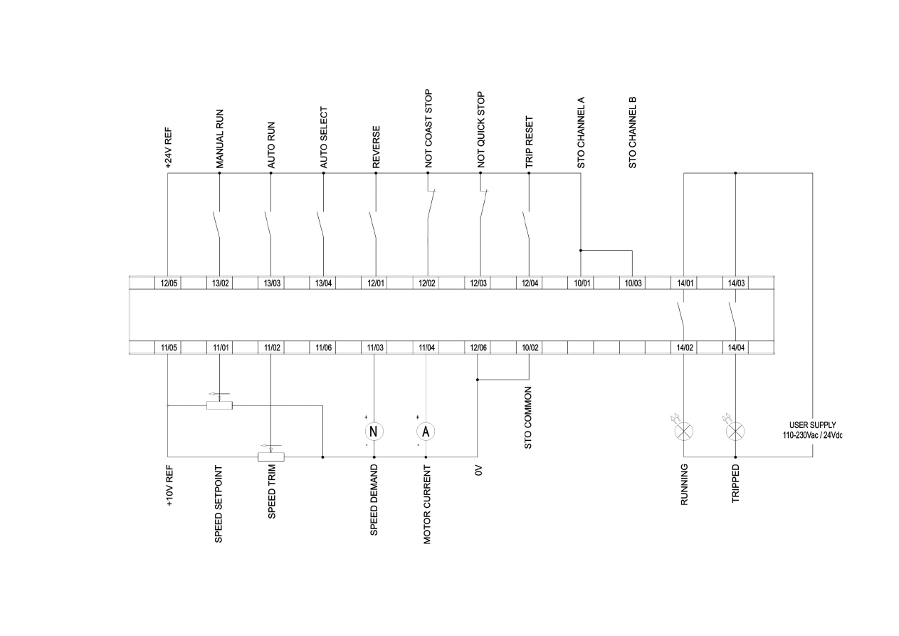


Installation 

4-30  


APPLICATION 2:   RAISE / LOWER TRIM 

Application 2:

“Speed Raise/Lower”

IDEAL FOR APPLICATIONS REQUIRING SPEED 

CONTROL FROM MULTIPLE LOCATIONS

ANIN 01 

(X11/01)

ANIN 02 

(X11/02)

RAMP

0486 

Acceleration Time

0487 

Deceleration Time

Not Used

Not Used

CURRENT LIMIT

V/F SHAPING

CT

VT

V

F

PWM CONTROL

I FDBK

F

V

F

V

0484 

Seq Stop Method

DIGIN 01

 (X13/02)

DIGIN 02 

(X13/03)

DIGIN 03 

(X13/04)

DIGIN 04

 (X12/01)

DIGIN 05

 (X12/02)

DIGIN 06

 (X12/03)

DIGIN 07

 (X12/02)

RUN

LOWER SPEED
RAISE/LOWER RESET

NOT COAST STOP
NOT QUICKSTOP

TRIP RESET

RAISE SPEED

0422 

Vhz Shape 

0457 

Base Frequency 

0447 

Fixed Boost 

0455 

Rated Motor Current

ANOUT 01 

(X11/03)

ANOUT 02 

(X11/04)

SPEED DEMAND

MOTOR CURRENT

SEQUENCING LOGIC

1901 

Ramp Time

1902 

Reset Value

1903 

Maximum Value

1904 

Minimum Value

RAISE/LOWER

MIN /MAX SPEED

1264 

Ref Min Speed Clamp

1265 

Ref Max Speed Clamp

0504 

Stop Ramp Time

0508 

Quickstop Ramp Time

FEEDBACKS

RUNNING

NOT

TRIPPED

RELAY 01

(X14/01)

(X14/02)

RELAY 02

(X14/03)

(X14/04)

RELAY 11

(X23/01)

(X23/02)

if AC30V

Requires IO Option 

7004-01-00

RELAY 12

(X23/03)

(X23/04)

if AC30V

Requires IO Option 

7004-01-00

OR

OR


Raise/Lower Trim Application 

This Application mimics the operation of a motorised potentiometer. Digital inputs allow the setpoint to be increased and decreased between 
limits. The limits and ramp rate can be set using the keypad. 
The Application is sometimes referred to as Motorised Potentiometer.


4-31 

Installation    


Raise/Lower Trim Wiring 


Installation 

4-32  


APPLICATION 3:  PRESETS SPEEDS 

ANIN 01 

(X11/01)

ANIN 02 

(X11/02)

RAMP

0486 

Acceleration Time

SPEED SETPOINT

SPEED TRIM

CURRENT LIMIT

V/F SHAPING

CT

VT

V

F

PWM CONTROL

I FDBK

F

V

F

V

0484 

Seq Stop Method

DIGIN 01

 (X13/02)

DIGIN 02 

(X13/03)

DIGIN 03 

(X13/04)

DIGIN 04

 (X12/01)

DIGIN 05

 (X12/02)

DIGIN 06

 (X12/03)

DIGIN 07

 (X12/02)

RUN

PRESET SELECT 2
PRESET SELECT 3
NOT COAST STOP
NOT QUICKSTOP
TRIP RESET

PRESET SELECT 1

0422 

Vhz Shape 

0457 

Base Frequency 

0447 

Fixed Boost 

0455 

Rated Motor Current

ANOUT 01 

(X11/03)

ANOUT 02 

(X11/04)

SPEED DEMAND

MOTOR CURRENT

1916  

Preset Speed 0 

1917  

Preset Speed 1 

1918  

Preset Speed 2 

1919  

Preset Speed 3 

1920  

Preset Speed 4 

1921  

Preset Speed 5 

1922  

Preset Speed 6 

1923  

Preset Speed 7 

    0V        0V         0V          0

    24V      0V         0V          1

    0V       24V        0V          2

    24V     24V        0V          3

    24V       0V        0V          4

    0V         0V        24V        5

   24V      24V        0V          6

   24V      24V       24V         7

SEQUENCING LOGIC

Application 3:

“Speed Presets”

IDEAL FOR GENERAL PURPOSE APPLICATIONS 

REQUIRING MULTIPLE DISCRETE SPEED LEVELS

Speeds

Preset

1   Setup
2   Clean
3   Operate  1
4   Operate  2

MIN /MAX SPEED

1265 

Ref Max Speed Clamp

1264 

Ref Min Speed Clamp

0487 

Deceleration Time

0504 

Stop Ramp Time

0508 

Quickstop Ramp Time

FEEDBACKS

RUNNING

NOT

TRIPPED

RELAY 01

(X14/01)

(X14/02)

RELAY 02

(X14/03)

(X14/04)

RELAY 11

(X23/01)

(X23/02)

if AC30V

Requires IO Option 

7004-01-00

RELAY 12

(X23/03)

(X23/04)

if AC30V

Requires IO Option 

7004-01-00

OR

OR

Presets Speeds Application 

This is ideal for applications requiring multiple discrete speed levels. 
The setpoint is selected from either the sum of the analogue inputs, (as in Application 1 and known here as PRESET 0), or as one of up to seven 
other pre-defined speed levels.  These are selected using DIN2, DIN3 and DIN4, refer to the Truth Table above. 
Edit parameters 

P

1917 to 

P

1923 on the keypad to re-define the speed levels of PRESET 1 to PRESET 7. Reverse direction is achieved by 

entering a negative speed setpoint. 

4-33 

Installation    


Presets Speeds Wiring 


Installation 

4-34  


APPLICATION 4:  PID CONTROL 

ANIN 01 

(X11/01)

ANIN 02 

(X11/02)

RAMP

0486 

Acceleration Time

PROCESS SETPOINT

PROCESS FEEDBACK

CURRENT LIMIT

V/F SHAPING

CT

VT

V

F

PWM CONTROL

I FDBK

F

V

F

V

0484 

Seq Stop Method

DIGIN 01 

(X13/02)

DIGIN 02 

(X13/03)

DIGIN 03 

(X13/04)

DIGIN 04 

(X12/01)

DIGIN 05 

(X12/02)

DIGIN 06 

(X12/03)

DIGIN 07 

(X12/02)

SEQUENCING LOGIC

RUN 

PID INTEGRAL DEFEAT

NOT STOP
NOT COAST STOP
NOT QUICKSTOP
TRIP RESET

PID ENABLE

0422 

Vhz Shape 

0457 

Base Frequency 

0447 

Fixed Boost 

0455 

Rated Motor Current

ANOUT 01 

(X11/03)

ANOUT 02 

(X11/04)

SPEED DEMAND

MOTOR CURRENT

Application 4:

“Process PID”

EASY TUNING FOR SETPOINT/FEEDBACK 

CONTROL APPLICATIONS REGULATING 

VOLUME OR PRESSURE, SUCH AS AIR 

HANDLING OR PUMPING

Speed

Setpoint

Pressure  or  Volume Feedback

Transducer

PID CONTROL


1928 

Proportional Gain

1929 

Integral TC

1930 

Derivative TC

1931 

Output Filter TC

1932 

Output Pos Limit

1933 

Output Neg Limit

1934 

Output Scaling

MIN /MAX SPEED

1264 

Ref Min Speed Clamp

1265 

Ref Max Speed Clamp

0487 

Deceleration Time

0504 

Stop Ramp Time

0508 

Quickstop Ramp Time

FEEDBACKS

RUNNING

NOT

TRIPPED

RELAY 01

(X14/01)

(X14/02)

RELAY 02

(X14/03)

(X14/04)

RELAY 11

(X23/01)

(X23/02)

if AC30V

Requires IO Option 

7004-01-00

RELAY 12

if AC30V

Requires IO Option 

7004-01-00

OR

OR

(X23/03)

(X23/04)


PID Control Application 

A simple application using a Proportional-Integral-Derivative 3-term controller. By default the setpoint is taken from AIN1, with feedback signal 
from the process on AIN2, scaling parameter 1939 swaps the routing of AIN1 & 2. The scale and offset features of the analogue input blocks may 
be used to correctly scale these signals. The difference between these two signals is taken as the PID error. The output of the PID block is then 
used as the inverter setpoint. 

4-35 

Installation    


PID Control Wiring 


Installation 

4-36  


APPLICATION 5:  ACTIVE FRONT-END


Application 5: 

“AFE”

ACTIVE FRONT END APPLICATION THAT ALLOWS THE 

DRIVE TO PERFORM REGENERATION OF ENERGY BACK 

INTO THE GRID, AND EXECUTES CONTROL OF 

EXTERNAL PRECHARGE SWITCHES AND CONTACTORS

M

AFE Drive

Motoring Drive

Grid

Motor


AFE Control Application 

A simple application that controls external precharge relays and contactors, and ensures that all pre-requisites for regenerative operation of the 
drive are satisfied. If the drive is used as an active front end this application MUST be loaded and enabled. If the shown control wiring to the 
control card terminals is correct no further modification to the application is needed to be able to run in AFE mode. (The line sync card needs to 
be wired to the encoder option too.)  

4-37 

Installation    


AFE Control Wiring – Excludes 7004-04-00 Wiring 


Installation 

4-38  


TERMINAL BLOCK WIRE RANGE 

 
Wire sizes for Europe should be chosen with respect to the operating conditions and your local National Electrical Safety Installation 
Requirements. Local wiring regulations always take precedence. For North American UL wire sizes refer to Appendix C: “Compliance” - 
Requirements for UL Compliance. 


Frame Size 

Power Terminals 

(minimum/maximum acceptance for aperture) 

Earth Connections 

Control Terminals 

Frame D 

0.05 - 6 mm

2


M4 ring crimp 

0.229 - 2.5 mm

Frame E 

0.05 – 6 mm

2


M4 ring crimp 

0.229 - 2.5 mm

Frame F  

1 - 10 mm

(*16 mm

2

M4 ring crimp 

0.229 – 2.5 mm

Frame G 

1.3 – 25 mm

2


M5 ring crimp 

0.229 – 2.5 mm

2


Frame H 

M8 post, accepting crimps or lugs up to width 26.5mm 

(minimum 25mm

2

 wire size) 

M8 ring crimp 

0.229 – 2.5 mm

2


Frame J 

M8 post, accepting crimps or lugs up to width 32mm 

(minimum 25mm

2

 wire size) 

M8 ring crimp 

Up to width 26.5mm 

0.229 – 2.5 mm

2


Frame K 

M12 post, accepting crimps or lugs up to width 38mm 

M8 ring crimp 

0.229 – 2.5 mm

2


*The larger wire size can be used provided a crimp is fitted to the wire 


4-39 

Installation    


TERMINAL TIGHTENING TORQUES 


Frame Size 

Power Terminals 

DC Bus Terminals 

Brake Terminals 

Ground Stud 

Frame D 

0.56-0.8Nm 

(5-7 lb-in) 

0.56-0.8Nm 

(5-7 lb-in) 

0.56-0.8Nm 

(5-7 lb-in) 

1.8Nm 

(16 lb-in) 

Frame E 

0.56-0.8Nm 

(5-7 lb-in) 

0.56-0.8Nm 

(5-7 lb-in) 

0.56-0.8Nm 

(5-7 lb-in) 

1.8Nm 

(16 lb-in) 

Frame F  

1.35Nm 

(12 lb-in) 

1.35Nm 

(12 lb-in) 

1.35Nm 

(12 lb-in) 

1.8Nm 

(16 lb-in) 

Frame G 

2.0Nm 

(18 lb-in) 

2.0Nm or 2.5Nm 

(18 lb-in or 22 lb-in) 

2.0Nm 

(18 lb-in) 

3.6Nm 

(32 lb-in) 

Frame H 

20Nm Max. 

(177 lb-in) 

20Nm Max. 

(177 lb-in) 

2.0Nm 

(18 lb-in) 

20Nm Max. 

(177 lb-in) 

Frame J 

20Nm Max. 

(177 lb-in) 

20Nm Max. 

(177 lb-in) 

20Nm Max. 

(177 lb-in) 

20Nm Max. 

(177 lb-in) 

Frame K 

38Nm Max. 

(336 lb-in) 

38Nm Max. 

(336 lb-in) 

38Nm Max. 

(336 lb-in) 

20Nm Max. 

(177 lb-in) 


1

 Cream or black coloured power terminals 2.0Nm (18 Ib-in) 

Green coloured power terminals 2.5Nm (22 lb-in) 


OPTIONAL EQUIPMENT 

Refer to Chapter 5 Associated Equipment. 
 

BRAKE WIRING 

Refer to Chapter 5 Associated Equipment on wiring details. 

Installation 

4-40  


Fitting a Remote GKP 

When fitting the GKP remotely to either a cubicle or panel mount it 

must 

be fitted to a flat surface.  Maximum cable length < 3 meters. 

  7001-00-00 – includes the GKP only 

  7001-00-01 - includes the GKP, 3m connection lead and screws. 


If ordered and supplied with the inverter the connection lead is

 NOT 

supplied, to order the lead the part number is LA501991U300. 

Cut out details: 


Gasket 

Reverse side of the 

GKP 

GKP – Reverse side 
 

The yellow dotted line is the cutout 
detail to allow remote fitting the 
connection lead, also shows screw 
hole details. 
 
Use M3 x 10 self tapping screws. 
 
Connection lead RS232/REM OP 
STA with a Steward 28A2025-OAO 
connector. 
 
All measurements in millimeter. 

4-41 

Installation    


Getting Started 

GKP SETUP WIZARD 

Purpose of the Setup Wizard 

The purpose of the setup wizard is to configure the inverter in a clear and concise manner.  

First familiarize yourself with Chapter 7 Graphical Keypad, for the keypad functions. 

Starting the Setup Wizard 

The Setup Wizard is automatically invoked when the inverter is reset to factory default settings. The setup 
wizard may be invoked at any other time by navigating to the Welcome Screen at the “top” of the menu 
tree the pressing the

key, Soft Key 1. 

Running the Setup Wizard 

At each point in the wizard pressing the OK key selects the displayed value and moves on to the next 
step. Pressing 

Soft Key 1

 moves back a step. Pressing the UP and DOWN keys modifies the selected 

value. 

Setup Wizard Stages 

After selecting the required view level and language, the next option is “Set Factory Defaults”. Changing this parameter to TRUE then pressing 
OK resets all parameters back to the default value determined by the inverters hardware configuration. If this choice is left FALSE the setup 
wizard starts with all parameters with their previously set values. Accepting each choice without change by pressing OK will result in no change to 
the inverter’s configuration. 
 
The rest of the Setup Wizard consists of a several sections. Each section corresponds to a functional component of the inverter, for example: 


Application selection 


IO Option, (includes the Encoder) 


Analog input and output ranges. 


Motor Data 


Motor Control 


Fieldbus options 


On-board Ethernet 


Auto tune 

 
If not required, any section may be skipped. 
 
The default setting for all parameters depends on earlier answers and on the physical configuration of the inverter.  All data entered is 
automatically saved without the need for any additional commands. 

Finalising Setup 

Once the Setup Wizard has been run to completion the feature is automatically disabled. Re-starting the inverter will not cause the Setup Wizard 
to be run again. (If it is desired to re-run the Setup Wizard, this can be achieved as detailed above in “Starting the Setup Wizard”). 
 
For complete details go to “Chapter 9 Setup Wizards”. 

OK key 

Soft Key 1 

Installation 

4-42  


ETHERNET COMMUNICATIONS 

 
The inverter comes with built-in Ethernet providing communications with the PC programming tools PDQ and PDD, a Modbus TCP server and a 
web server.  See Chapter 12 - Ethernet for recommended cable information. 
 

Connecting the Ethernet Cable – AC30V 


Disconnecting the Ethernet Cable – AC30V 
 

To remove the cable first remove the GKP and then insert a 
screwdriver to release the catch on the Ethernet clip. 

4-43 

Installation    


Connecting the Ethernet Cables – AC30P and AC30D 


DO NOT TOUCH 

DO NOT touch the board surface via the aperture shown 

Installation 

4-44  


Setting the IP Address 

The inverter’s Ethernet requires an IP address to participate in communications.  The factory default is set so that an IP address is selected 
automatically depending on the network on which it is connected.  It may obtain an IP address using DHCP or Auto-IP. 

DHCP 

If the network has a DHCP (Dynamic Host Communications Protocol) server, then the inverter will obtain an address from this.   

Auto-IP 

If the network has no DHCP server or if connecting the inverter directly to a PC then the IP address will be chosen randomly by the inverter from 
the link-local address range 169.254.*.*.  Note that when connecting the inverter directly to a PC it may take 1 – 2 minutes for the PC to obtain a 
link-local address. 
 

Manual 

The IP address may be fixed if required.  The DHCP and Auto-IP must both be disabled. 
 
 
The current IP address of the inverter may be monitored using the following parameters 

0926 IP Address, 0927 Subnet Mask, 0928 Gateway 

Address, 

found in menu: 

Parameters::Base Comms::Ethernet


The state of the Ethernet may be monitored using the parameter 

0919 Ethernet State 

and from the Ethernet icon on the GKP status bar. 


More Information 

For more information on customizing and troubleshooting the inverter’s Ethernet see Chapter 12 – Ethernet.   
 
Accessing the inverter’s web page is also described in Chapter 12 and information on using the Modbus TCP server can be found in Appendix A 
- Modbus TCP. 


Content      ..     2      3      4      5     ..