Parker Torqmotor Service Procedure (TC, TS, TB, TE, TJ, TF, TG, TH and TL Series). Manual (2007) - page 3
HY13-1512-006-M1/USA
Torqmotor™ Service Procedure
Disassembly and Inspection
TC, TS, TB, TE, TJ, TF, TG, TH and TL Series
Inspect housing
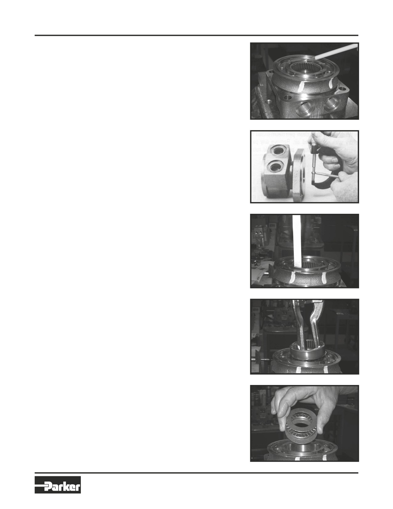
21. If the housing (18) assembly has passed
bearing/bushing
inspection to this point, inspect the housing
bearings/bushings (19) and (13) and if they
are captured in the housing cavity the two
thrust washers (14) and thrust bearing (15).
The bearing rollers must be firmly retained
in the bearing cages, but must rotate and
orbit freely. All rollers and thrust washers
must be free of brinelling and corrosion.
SEE FIGURE 27. The TB Series bushing (19)
or (13) to coupling shaft diameter clearance
Figure 27
must not exceed .010 inch (.025 mm). A
bearing, bushing, or thrust washer that does
not pass inspection must be replaced. SEE
FIGURE 28. If the housing has passed this
inspection the disassembly of the Torqmo-
tor™ is completed.
NOTE
NOTE: The depth or location of bear-
ing/bushing (13) in relation to the housing
Figure 28
wear plate surface and the depth or loca-
tion of bearing/bushing (19) in relation to
the beginning of bearing/bushing coun-
ter bore should be measured and noted
before removing the bearings/bushings.
This will facilitate the correct
reassembly of new bearings/bushings.
SEE FIGURE 29.
Figure 29
Remove
22. If the bearings, bushing or thrust washers
bearings
must be replaced use a suitable size bear-
or bushings
ing puller to remove bearing/bushings (19)
& thrust
and (13) from housing (18) without damag-
washers
ing the housing. Remove thrust washers
(14) and thrust bearing (15) if they were
previously retained in the housing by bear-
ing (13). SEE FIGURES 30 & 31.
Figure 30
THE DISASSEMBLY OF TORQMOTOR™ IS COMPLETED.
Figure 31
37
Parker Hannifin Corporation
Hydraulic Pump/Motor Division
Greeneville, TN 37745 US
HY13-1512-006-M1/USA
Torqmotor™ Service Procedure
Torqmotor™ Assembly
TC, TS, TB, TE, TJ, TF, TG, TH and TL Series
• Replace all seals and seal rings with new ones each time you reassemble the Torqmotor™ unit. Lubricate all
seals and seal rings with SAE 10W40 oil or clean grease before assembly.
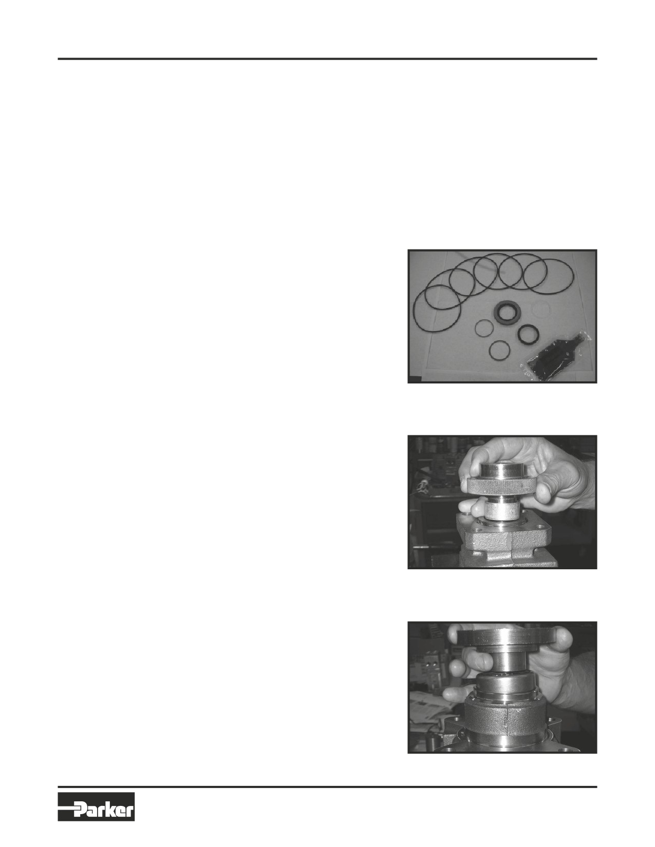
• NOTE: Individual seals and seal rings as well as a complete seal kit are available. SEE FIGURE 32.
The parts should be available through most OEM parts distributors or Parker approved Torqmotor™
distributors. (Contact your local dealer for availability).
• NOTE: Unless otherwise indicated, do not oil or grease parts before assembly.
• Wash all parts in clean petroleum-based solvents before assembly. Blow them dry with compressed air. Re-
move any paint chips from mating surfaces of the end cover, commutator set, manifold rotor set, wear plate
and housing and from port and sealing areas.
WARNING
WARNING: SINCE THEY ARE FLAMMA-
BLE, BE EXTREMELY CAREFUL WHEN
USING ANY SOLVENT. EVEN A SMALL
4
EXPLOSION OR FIRE COULD CAUSE
INJURY OR DEATH.
3
20
WARNING
WARNING: WEAR EYE PROTECTION
AND BE SURE TO COMPLY WITH OSHA
17
16
OR OTHER MAXIMUM AIR PRESSURE
25
REQUIREMENTS.
Press in outer
1.
If the housing (18) bearing components were
Figure 32, TF, TG seal kit
bearing/bushing
removed for replacement, thoroughly coat
and pack a new outer bearing/bushing (19)
with clean corrosion resistant grease recom-
mended in the material section. Press the
new bearing/bushing into the counterbore at
the mounting flange end of the housing, using
the appropriate sized bearing mandrel such
as described in figure 1 or figure 2 which will
control the bearing/ bushing depth.
Small Frame Series TC, TS, TB and TE Torq-
motor™ housings require the use of bearing
mandrel shown in figure 1 to press bearing/
bushing (19) into the housing to a required
Figure 33
depth of .151/.161 inches (3.84/4.09 mm)
from the end of the bearing counterbore. SEE
FIGURE 33. (TC reference page 10).
Large Frame Series TF, TL, TG & TJ Torqmo-
tor™ housings require the use of the bearing
mandrel shown in figure 2 to press bearing
(19) into the housing to a required depth of
.290/.310 inches (7.37/7,87 mm) from the
outside end of the bearing counterbore.
SEE FIGURE 34.
Large Frame Series TH Torqmotor housings
require the use of a bearing mandrel. Consult
factory for specifications.
Figure 34
38
Parker Hannifin Corporation
Hydraulic Pump/Motor Division
Greeneville, TN 37745 US
HY13-1512-006-M1/USA
Torqmotor™ Service Procedure
Torqmotor™ Assembly
TC, TS, TB, TE, TJ, TF, TG, TH and TL Series
NOTE
NOTE: Bearing mandrel must be pressed
against the lettered end of bearing shell.
Take care that the housing bore is square
with the press base and the bearing/
bushing is not cocked when pressing a
bearing/bushing into the housing.
CAUTION
CAUTION: If the bearing mandrel speci-
fied in the “Tools and Materials Required
for Servicing” section is not available and
alternate methods are used to press in
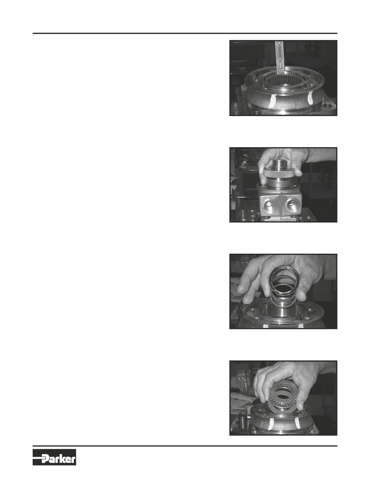
Figure 35
bearing/bushing (13) and (19) the bear-
ing/bushing depths specified must be
achieved to insure adequate bearing
support and correct relationship to adja-
cent components when assembled. SEE
FIGURE 35.
CAUTION
CAUTION: Because the bearing/bush-
ings (13) and (19) have a press fit into the
housing they must be discarded when
removed. They must not be reused.
Figure 36
Press in inner
2.
The Small Frame Series TC, TB, TS and TE
bearing/bushing
Torqmotor™ inner housing bearing/bushing
(13) can now be pressed into its counter-
bore in housing (18) flush to .03 inch (.76
mm) below the housing wear plate contact
face. Use the opposite end of the bearing
mandrel that was used to press in the outer
bearing/bushing (19). Reference figure 1,
“Tools and Materials Required for Servicing”
section. SEE FIGURE 36.
The Large Frame Series TF, TL, TG & TJ
Torqmotor™ housing (18) requires that you
assemble a new backup washer (25) &
Figure 37
backup ring (17), new seal (16), with the lip
facing to the inside of Torqmotor (see figure
69A), new thrust washer (14), new thrust
bearing (15) and a new second thrust wash-
er (14) in that order before pressing in the
inner housing bearing (13). SEE FIGURE 37
& 38. When these components are in place,
press new bearing (13) into the housing (18)
to a depth of .105/.125 inches (2.67/3.18),
.03 inches max for TJ (.76) below the hous-
ing wear plate contact face. Use the op-
posite end of the bearing mandrel used to
press in outer bearing (19). Reference figure
2, in the “Tools and Materials Required for
Servicing” section. SEE FIGURE 39.
Figure 38
39
Parker Hannifin Corporation
Hydraulic Pump/Motor Division
Greeneville, TN 37745 US
HY13-1512-006-M1/USA
Torqmotor™ Service Procedure
Torqmotor™ Assembly
TC, TS, TB, TE, TJ, TF, TG, TH and TL Series
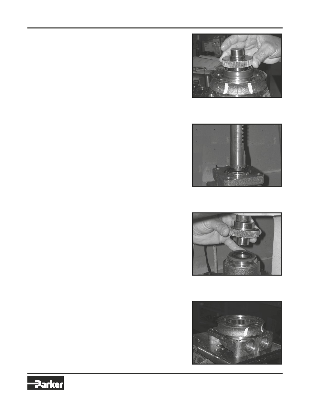
Press in dirt &
3. Press a new dirt and water seal (20) into the
water seal
housing (18) outer bearing counterbore.
Figure 39
The Small Frame Series TC, TS, TB and TE
Torqmotor™ dirt and water seal (20) must
be pressed in until its’ flange is flush against
the housing. SEE FIGURE 40.
Figure 40
The Large Frame Series TF, TL, TG, TJ & TH
Torqmotor™ dirt and water seal (20) must
be pressed in with the lip facing out and
until the seal is flush to .020 inches (.51 mm)
below the end of housing. SEE FIGURE 41.
Figure 41
Place housing
4. Place housing (18) assembly into a soft
assembly
jawed vise with the coupling shaft bore
into vice
down, clamping against the mounting
flange. SEE FIGURE 42.
Figure 42
40
Parker Hannifin Corporation
Hydraulic Pump/Motor Division
Greeneville, TN 37745 US
HY13-1512-006-M1/USA
Torqmotor™ Service Procedure
Torqmotor™ Assembly
TC, TS, TB, TE, TJ, TF, TG, TH and TL Series
Assemble backup
5.
On Small Frame, Series TC, TS, TB & TE
washer & seal
Torqmotors™ assemble a new backup ring
(17), new bakcup washer (25) and new seal
(16) with the seal lip facing toward the inside
of Torqmotor™ (see Figure 69B), into their
respective counterbores in housing (18) if
they were not assembled in procedure 2.
Large Frame, Series TF, TG, TJ & TH Torq-
motor™ housing (18) that did not require
replacement of the bearing package will
Figure 43
require that the two “captured” thrust wash-
ers (14) and thrust bearing (15) be unseated
and vertical to the counterbore and the
new backup ring (17), new backup washer
(25), and new seal (16) be worked around
the thrust bearing package and placed into
their respective counterbores. The seal lip
must face out of the seal counterbore and
toward the inside of Torqmotor™ (see figure
69A). Be sure the thrust bearing package is
reseated correctly after assembly of the seal
and backup washer. SEE FIGURES 43 & 44.
CAUTION
CAUTION: Original design Large Frame,
Figure 44
TF & TG Torqmotors™ that do not have
backup washer (25) when disassembled
must be assembled with a new backup
ring (17), new backup washer (25), and
new seal (16).
Assemble thrust
6.
Assemble thrust washer (14) then thrust
washer & bearing
bearing (15) that was removed from the
Series TC, TB, TS or TE Torqmotor™. SEE
FIGURE 45.
NOTE
NOTE: Small Frame Series TC, TS, TB
and TE Torqmotors™ require one thrust
washer (14) with thrust bearing (15). The
coupling shaft will be seated directly
Figure 45
against the thrust bearing.
Apply masking
7. Apply masking tape around splines or
tape to shaft
keyway on shaft (12) to prevent damage to
seal. SEE FIGURE 46.
Figure 46
41
Parker Hannifin Corporation
Hydraulic Pump/Motor Division
Greeneville, TN 37745 US
HY13-1512-006-M1/USA
Torqmotor™ Service Procedure
Torqmotor™ Assembly
TC, TS, TB, TE, TJ, TF, TG, TH and TL Series
Install
8.
Be sure that a generous amount of clean
coupling
corrosion resistant grease has been applied
shaft
to the lower (outer) housing bearing/bushing
(19). Install the coupling shaft (12) into hous-
ing (18), seating it against the thrust bearing
(15) in TC, TS, TB and TE Series housings
and against the second thrust washer (14)
in TF, TL, TG and TH Series housings. SEE
FIGURE 47.
CAUTION
CAUTION: The outer bearing (19) is not
Figure 47
lubricated by the system’s hydraulic
fluid. Be sure it is thoroughly packed with
the recommended grease, Parker Gear
grease specification #045236, E/M Lubri-
cant #K-70M.
NOTE
NOTE: Mobil Mobilith SHC ® 460
NOTE: A 102 Tube (P/N 406010) is includ-
ed in each seal kit.
NOTE
NOTE: The coupling shaft (12) will be
flush or just below the housing wear
surface on Small Frame, Series TC, TS,
TB, TE & TJ Torqmotors™ when properly
seated while the coupling shaft (12) on
Figure 48
Large Frame, Series TF, TL, TG, or TH
Torqmotors™ will be approximately .10
inch (2.54 mm) below the housing wear
plate surface to allow the assembly of
thrust bearing (11). The coupling shaft
must rotate smoothly on the thrust bear-
ing package. SEE FIGURE 48.
Install thrust
9.
Install thrust bearing (11) onto the end of
bearing
coupling shaft (12) only if you are servicing
an TF, TL, TG, TH or TL Series Torqmotor™.
SEE FIGURE 49.
Insert seal
10. Apply a small amount of clean grease to a
Figure 49
ring
new seal ring (4) and insert it into the hous-
ing (18) seal ring groove. SEE FIGURE 50.
NOTE
NOTE: One or two alignment studs
screwed finger tight into housing (18) bolt
holes, approximately 180 degrees apart,
will facilitate the assembly and alignment
of components as required in the follow-
ing procedures. The studs can be made
by cutting off the heads of either
3/8-24 UNF 2A or 5/16-24 UNF 2A bolts
as required that are over .5 inch (12.7
mm) longer than the bolts (1, 1A, 1B, or
1C) used in the Torqmotor™.
Figure 50
42
Parker Hannifin Corporation
Hydraulic Pump/Motor Division
Greeneville, TN 37745 US
HY13-1512-006-M1/USA
Torqmotor™ Service Procedure
Torqmotor™ Assembly
TC, TS, TB, TE, TJ, TF, TG, TH and TL Series
Install
11. Install drive link (10) the long splined end
drive link
down into the coupling shaft (12) and en-
gage the drive link splines into mesh with
the coupling shaft splines. SEE FIGURE 51.
NOTE
NOTE: Use any alignment marks put on
the coupling shaft and drive link before
disassembly to assemble the drive link
splines in their original position in the
mating coupling shaft splines.
Figure 51
Assemble
12. Assemble wear plate (9) over the drive link
wear plate
(10) and alignment studs onto the housing
(18). SEE FIGURE 52.
Assemble
13. Apply a small amount of clean grease to a
seal ring
new seal ring (4) and assemble it into the
Figure 52
seal ring groove on the wear plate side of
the rotor set stator (8B). SEE FIGURE 53.
Install the
14. Install the assembled rotor set (8) onto wear
assembled
plate (9) with rotor (8A) counterbore and seal
rotor set
ring side down and the splines into mesh
with the drive link splines. SEE FIGURE 54.
NOTE
NOTE: It may be necessary to turn one
alignment stud out of the housing (18)
temporarily to assemble rotor set (8) or
manifold (7) over the drive link.
Figure 53
NOTE
NOTE: If necessary, go to the appropri-
ate, “Rotor Set Component Assembly
Procedure.”
NOTE
NOTE: The rotor set rotor counterbore
side must be down against wear plate for
drive link clearance and to maintain the
original rotor-drive link spline contact. A
rotor set without a counterbore and that
was not etched before disassembly can
be reinstalled using the drive link spline
pattern on the rotor splines if apparent,
to determine which side was down. The
rotor set seal ring groove faces toward
the wear plate (9).
Figure 54
43
Parker Hannifin Corporation
Hydraulic Pump/Motor Division
Greeneville, TN 37745 US
HY13-1512-006-M1/USA
Torqmotor™ Service Procedure
Torqmotor™ Assembly
TC, TS, TB, TE, TJ, TF, TG, TH and TL Series
Assemble
15. Apply clean grease to a new seal ring (4)
seal ring
and assemble it in the seal ring groove in
in manifold
the rotor set contact side of manifold (7).
SEE FIGURE 55.
NOTE
NOTE: The manifold (7) is made up of
several plates bonded together perma-
nently to form an integral component.
The manifold surface that must contact
the rotor set has it’s series of irregular
shaped cavities on the largest circumfer-
Figure 55
ence or circle around the inside diameter.
The polished impression left on the mani-
fold by the rotor set is another indication
of which surface must contact the rotor
set.
Assemble
16. Assemble the manifold (7) over the align-
manifold
ment studs and drive link (10) and onto the
rotor set. Be sure the correct manifold sur-
face is against the rotor set. SEE FIGURE
56.
Figure 56
Insert a seal
17. Apply grease to a new seal ring (4) and
in manifold
insert it in the seal ring groove exposed on
the manifold. SEE FIGURE 57.
Figure 57
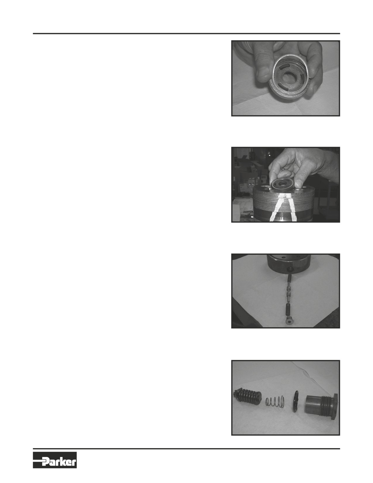
Assemble
18. Assemble the commutator ring (6) over
commutator ring
alignment studs onto the manifold. SEE
FIGURE 58.
Figure 58
44
Parker Hannifin Corporation
Hydraulic Pump/Motor Division
Greeneville, TN 37745 US
HY13-1512-006-M1/USA
Torqmotor™ Service Procedure
Torqmotor™ Assembly
TC, TS, TB, TE, TJ, TF, TG, TH and TL Series
Assemble
19. Assemble a new seal ring (3) flat side up,
seal &
into commutator (5) and assemble com-
commutator
mutator over the end of drive link (10) onto
manifold (7) with seal ring side up. SEE
FIGURE 59, 60.
Figure 59
Figure 60
Assemble shuttle
20. If shuttle valve components items #21, #22,
valve parts into
#23, #24 were removed from the end cover
end cover
(2) turn a plug (21) with a new o-ring (22),
loosely into one end of the valve cavity in
the end cover. Insert a spring (23) the valve
(24) and the second spring (23) into the
other end of the valve cavity. Turn the sec-
ond plug (21) with a new o-ring (22) loosely
into the end cover valve cavity. 3/16 inch
Allen wrench required. SEE FIGURE 61.
Figure 61
Assemble relief
21. If relief valve components items #21, #22,
valve parts in
#24 were removed from the end cover (2)
end cover
assemble a new o-ring (22) on the two
plugs (21). Assemble a two piece relief valve
(24) in each of the plugs, with the large end
of the conical spring into the plug first and
the small nut of the other valve piece in the
small end of the conical spring. Turn each
of the plug and relief valve assemblies into
the end cover loosely to be torqued later.
3/8 inch Allen or 1 inch Hex socket required.
SEE FIGURE 62.
Figure 62
45
Parker Hannifin Corporation
Hydraulic Pump/Motor Division
Greeneville, TN 37745 US
HY13-1512-006-M1/USA
Torqmotor™ Service Procedure
Torqmotor™ Assembly
TC, TS, TB, TE, TJ, TF, TG, TH and TL Series
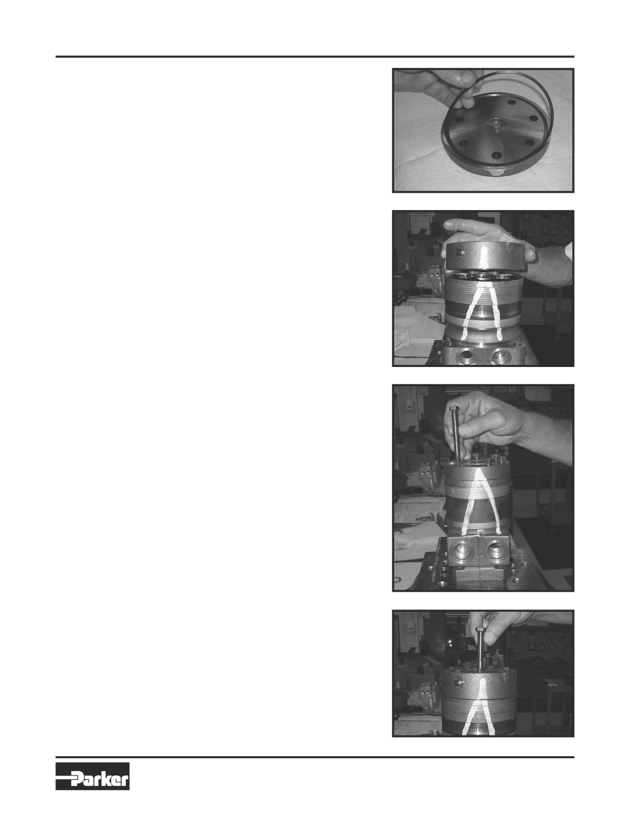
Assemble seal
22. Assemble a new seal ring (4) into end cover
ring &
(2) and assemble end cover over the align-
end cover
ment studs and onto the commutator set.
SEE FIGURE 63, 64. If the end cover has
only 5 bolt holes be sure the cover holes are
aligned with the 5 threaded holes in hous-
ing (18). The correct 5 bolt end cover bolt
hole relationship to housing port bosses is
shown in FIGURE 65.
Figure 63
NOTE
NOTE: If the end cover has a valve (24)
or has five bolt holes, use the line you
previously scribed on the cover to radi-
ally align the end cover into its original
position.
Figure 64
Assemble
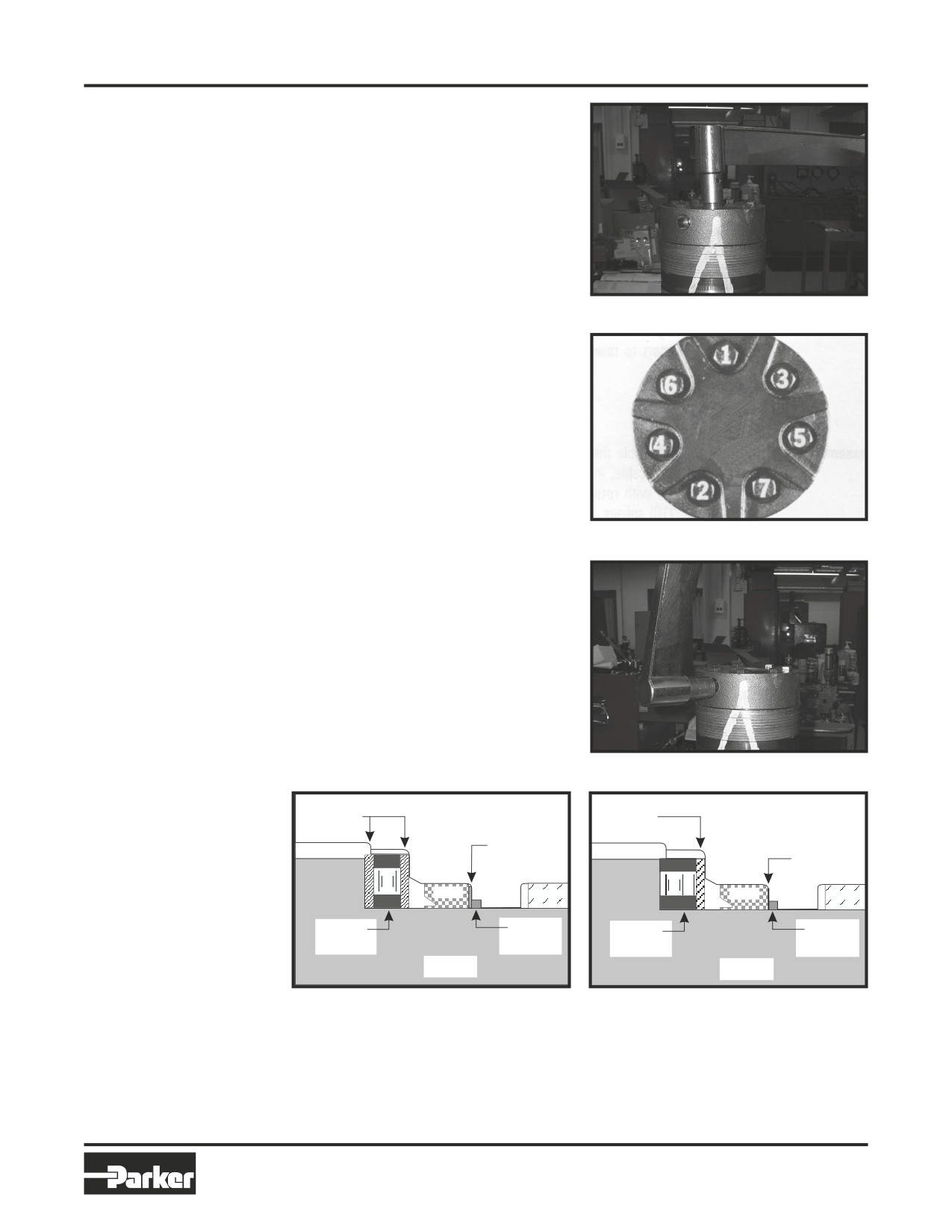
23. Assemble the 5, 6 or 7 special bolts (1, 1A,
Figure 65
cover bolts
1B or 1C) and screw in finger tight. Remove
and replace the two alignment studs with
bolts after the other bolts are in place. Al-
ternately and progressively tighten the bolts
to pull the end cover and other components
into place with a final torque of 25-30 ft. lbs.
(34-41 N m) for the five TC, TS, TB or six TE
Series 5/16 24 threaded bolts or six TJ bolts
or 50-55 ft. lbs. (68-75 N m) for the seven
TF, TL, TG & TH Series 3/8-24 threaded
bolts. SEE FIGURE 66, 67, 68.
Figure 66
46
Parker Hannifin Corporation
Hydraulic Pump/Motor Division
Greeneville, TN 37745 US
HY13-1512-006-M1/USA
Torqmotor™ Service Procedure
Torqmotor™ Assembly
TC, TS, TB, TE, TJ, TF, TG, TH and TL Series
NOTE
NOTE: The special bolts required for use
with the relief or shuttle valve (24) end
cover assembly (2) are longer than the
bolts required with standard and cover
assembly. Refer to the individual service
parts lists or parts list charts for correct
service part number if replacement is
required.
Figure 67
Figure 68
Torque the
24. Torque the two shuttle valve plug assem-
valve plugs
blies (21) in end cover assembly to 9-12 ft.
lbs. (12-16 N m) if cover is so equipped.
SEE FIGURE 69.
Torque the two relief valve plug assemblies
(21) in end cover assembly to 45-55 ft. lbs.
(61-75 N m) if cover is so equipped.
Figure 69
Thrust
Thrust
Housing
Washers
Washers
Housing
Steel
Washer
Steel
Washer
Seal
Seal
Thrust
Backup
Thrust
Backup
Bearing
Washer
Bearing
Washer
Shaft
Shaft
Not To Scale
Not To Scale
Figure 69A
Large Frame Figure 69B
Small Frame
THE ASSEMBLY OF THE TORQMOTOR™ IS NOW COMPLETE EXCEPT FOR WOODRUFF KEY (12A), NUT
(12B), WASHER (12C), BOLT (12D), LOCKWASHER (12E), RETAINER RING (12F) or PORT O-RINGS (18A) AT
INSTALLATION IF APPLICABLE. PROCEED TO FINAL CHECKS SECTION.
47
Parker Hannifin Corporation
Hydraulic Pump/Motor Division
Greeneville, TN 37745 US
HY13-1512-006-M1/USA
Torqmotor™ Service Procedure
Rotor Set Component Assembly
TC, TS, TB, TE, TJ, TF, TG, TH and TL Series
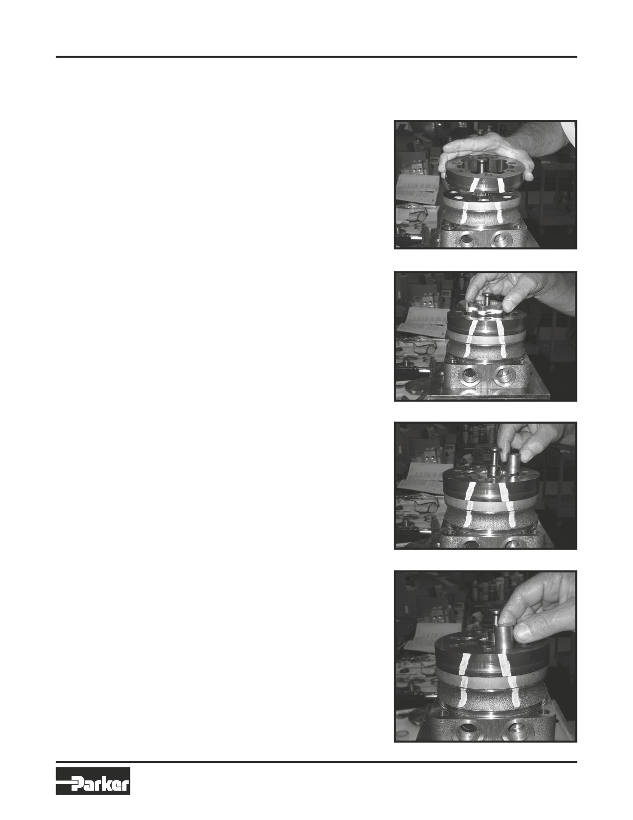
One Piece Stator Construction
A disassembled rotor (8A) stator (8B) and vanes (8C) that cannot be readily assembled by hand can be assem-
bled by the following procedures.
Assemble stator
1.
Place stator (8B) onto wear plate (9) with
seal ring (4) side down, after following Torq-
motor™ assembly procedures 1 through
13. Be sure the seal ring is in place. SEE
FIGURE 70.
Insert
2.
If assembly alignment studs are not being
two bolts
utilized, align stator bolt holes with wear
plate and housing bolt holes and turn two
bolts (1) finger tight into bolt holes approxi-
mately 180 degrees apart to retain stator
and wear plate stationary.
Figure 70
Assemble rotor
3.
Assemble the rotor (8A), counterbore down
if applicable, into stator (8B), and onto wear
plate (9) with rotor splines into mesh with
drive link (10) splines. SEE FIGURE 71.
NOTE
NOTE: If the manifold side of the rotor
was etched during Torqmotor disassem-
bly, this side should be up. If the rotor is
not etched and does not have a coun-
terbore, use the drive link spline contact
pattern apparent on the rotor splines to
Figure 71
determine the rotor side that must be
against the wear plate.
Assemble vanes
4. Assemble six vanes (8C), or as many vanes
that will readily assemble into the stator
vane pockets. SEE FIGURE 72.
CAUTION
CAUTION: Excessive force used to push
the rotor vanes into place could shear
off the coating applied to the stator vane
pockets.
Figure 72
Assemble full
complement
5. Grasp the output end of coupling shaft (12)
of vanes
with locking pliers or other appropriate
turning device and rotate coupling shaft,
drive link and rotor to seat the rotor and the
assembled vanes (8C) into stator (8B), cre-
ating the necessary clearance to assemble
the seventh or full complement of seven
vanes. Assemble the seven vanes using
minimum force. SEE FIGURE 73.
Remove two
assembled bolts
6. Remove the two assembled bolts (1) if used
to retain stator and wear plate.
Go to Torqmotor™ assembly procedure
#15, to continue Torqmotor™ assembly.
Figure 73
48
Parker Hannifin Corporation
Hydraulic Pump/Motor Division
Greeneville, TN 37745 US
HY13-1512-006-M1/USA
Torqmotor™ Service Procedure
Rotor Set Component Assembly
TC, TS, TB, TE, TJ, TF, TG, TH and TL Series
Two Piece Stator Construction
A disassembled rotor set (8) that cannot be readily assembled by hand and has a two piece stator can be
assembled by the following procedures.
Assemble
1. Place stator half (8B) onto wear plate (9) with
stator halves
seal ring (4) side down, after following Torqmo-
tor™ assembly procedures 1 through 13. Be
sure the seal ring is in place.
Insert two
2. Align stator bolt holes with wear plate and
alignment
housing bolts and turn two alignment studs
studs
finger tight into bolt holes approximately 180
degrees apart to retain stator half and wear
plate stationary.
Assemble rotor
3. Assemble rotor (8A), counterbore down if appli-
cable, into stator half (8B), and onto wear plate
(9) with rotor splines into mesh with drive link
(10) splines.
NOTE
NOTE: Use any marking you applied to rotor
set components to reassemble the compo-
nents in their original relationship to ensure
ultimate wear life and performance.
Assemble vanes
4. Assemble six vanes (8C), or as many vanes that
will readily assemble into the stator vane pock-
ets.
CAUTION
CAUTION: Excessive force used to push the
rotor vanes into place could shear off the
coating applied to the stator vane pockets.
Assemble full
5. Grasp the output end of coupling shaft (12)
complement
with locking pliers or other appropriate turning
of vanes
device and rotate coupling shaft, drive link and
rotor to seat the rotor and the assembled vanes
(8C) into stator half (8B), creating the neces-
sary clearance to assemble the seventh or full
complement of seven vanes. Assemble the
seven vanes using
minimum force.
Assemble seal
6. Place second stator half (8D) on a flat surface
ring in stator
with seal ring groove up. Apply a small amount
half
of grease to a new seal ring (4) and assemble it
into stator half ring groove.
49
Parker Hannifin Corporation
Hydraulic Pump/Motor Division
Greeneville, TN 37745 US
HY13-1512-006-M1/USA
Torqmotor™ Service Procedure
Rotor Set Component Assembly
TC, TS, TB, TE, TJ, TF, TG, TH and TL Series
Assemble second
7. Assemble the second stator half (8D) over the
stator half
two alignment studs and rotor (8A) with seal ring
side down onto the first stator half (8B) aligning
any timing marks applied for this purpose.
CAUTION
CAUTION: If the stator half (8B) is a different
height (thickness) than stator half (8D) the
stator vanes (8C) or (8E) of the same length
(height) as the stator half must be reas-
sembled in their respective stator half for the
rotor set to function properly.
Assemble vanes
8. Assemble six vanes (8E), or as many vanes that
will readily assemble into the stator vane pock-
ets.
Assemble full
9. Grasp the output end of coupling shaft (12)
complement
with locking pliers or other appropriate turn-
of vanes
ing device and rotate coupling shaft, drive link
and rotor to seat the rotor and the assembled
vanes (8E) into stator (8D), creating the neces-
sary clearance to assemble the seventh or full
complement of seven vanes. Assemble the
seven vanes using minimum force.
Go to Torqmotor™ assembly procedure #15, to
continue Torqmotor™ assembly.
50
Parker Hannifin Corporation
Hydraulic Pump/Motor Division
Greeneville, TN 37745 US
HY13-1512-006-M1/USA
Torqmotor™ Service Procedure
Final Checks
TC, TS, TB, TE, TJ, TF, TG, TH and TL Series
Final Checks
• Pressurize the Torqmotor™ with 100 p.s.i. dry air or nitrogen and submerge in solvent to check for
external leaks.
• Check Torqmotor™ for rotation. Torque required to rotate coupling shaft should not be more than
50 ft. lbs. (68 N m)
• On TC, TS, TB, TE & TJ Series Torqmotors, pressure port with “A” cast under it on housing (18) is for clock-
wise coupling shaft rotation as viewed from the output end of coupling shaft. Pressure port with “B” cast
under it is for counter clockwise coupling shaft rotation.
• On TF, TL, TG, & TH Series Torqmotors, pressure port with “B” cast under it on housing (18) is for clockwise
coupling shaft rotation as viewed from the output end of coupling shaft. Pressure port with “A” case under
it is for counter clockwise coupling shaft rotation.
• Use test stand if available, to check operation of the Torqmotor™.
Hydraulic Fluid
Keep the hydraulic system filled with one of the following:
•
10W40 SE or SF manufacturers suggested oil.
• Hydraulic fluid as recommended by equipment manufacturer, but the viscosity should not drop below 50
SSU or contain less than .125% zinc anti-wear additives.
CAUTION: Do not mix oil types. Any mixture, or an unapproved oil, could deteriorate the seals. Main-
tain the proper fluid level in the reservoir. When changing fluid, completely drain old oil from the sys-
tem. It is suggested also that you flush the system with clean oil.
Filtration
Recommended filtration 20-50 micron.
Oil Temperature
Maximum operating temperature 200°F (93.3° C).
51
Parker Hannifin Corporation
Hydraulic Pump/Motor Division
Greeneville, TN 37745 US
HY13-1512-006-M1/USA
Torqmotor™ Service Procedure
Tips
TC, TS, TB, TE, TJ, TF, TG, TH and TL Series
Tips for Maintaining the Torqmotor™ Hydraulic System
•
Adjust fluid level in reservoir as necessary.
•
Encourage all operators to report any malfunction or accident that may have damaged the hydraulic system
or component.
•
Do not attempt to weld any broken Torqmotor™ component. Replace the component with original equip-
ment only.
•
Do not cold straighten, hot straighten, or bend any Torqmotor™ part.
•
Prevent dirt or other foreign matter from entering the hydraulic system. Clean the area around and the filler
caps before checking oil level.
•
Investigate and correct any external leak in the hydraulic system, no matter how minor the leak.
•
Comply with manufacturer’s specifications for cleaning or replacing the filter.
CAUTION: Do not weld, braze, solder or any way alter any Torqmotor™ component.
CAUTION: Maximum operating pressure must not exceed recommended Torqmotor™ pressure ca-
pacity.
CAUTION: Always carefully inspect any system component that may have been struck or damaged
during operation or in an accident. Replace any component that is damaged or that is questionable.
CAUTION: Do not force any coupling onto the Torqmotor™ coupling shaft as this could damage the
unit internally.
Parker extends close technical cooperation and assistance. If problems occur which you cannot solve,
please contact your local Parker approved Distributor or Parker Technical Support. Our phone number and
fax number and address are on the back cover of this manual.
52
Parker Hannifin Corporation
Hydraulic Pump/Motor Division
Greeneville, TN 37745 US
HY13-1512-006-M1/USA
Torqmotor™ Service Procedure
Notes
TC, TS, TB, TE, TJ, TF, TG, TH and TL Series
53
Parker Hannifin Corporation
Hydraulic Pump/Motor Division
Greeneville, TN 37745 US
HY13-1512-006-M1/USA
Torqmotor™ Service Procedure
Notes
TC, TS, TB, TE, TJ, TF, TG, TH and TL Series
54
Parker Hannifin Corporation
Hydraulic Pump/Motor Division
Greeneville, TN 37745 US