Parker Torqmotor Service Procedure (TC, TS, TB, TE, TJ, TF, TG, TH and TL Series). Manual (2007) - page 2
HY13-1512-006-M1/USA
Torqmotor™ Service Procedure
TB Service Parts List Chart
TC, TS, TB, TE, TJ, TF, TG, TH and TL Series
EXPLODED VIEW
ITEM #
12
12A
12B
COUPLING
WOODRUFF
DESCRIPTION
SHAFT
KEY
NUT
01-
Long 6B Snapwire Groove
MF019007
09-
1” Ø, 0.38 Pinhole, 0.55” from end
MF019000
10-
1” Short Woodruff Key 1/4” Tap
MF019006
038015 (1/4x1)
11-
1” Short 6B Spline, 1/4” Snapwire Groove
MF019003
12-
1” Tapered (Short)
MF019004
038015 (1/4x1)
025136
13-
1” Long Woodruff Snapwire Groove
MF019005
038015 (1/4x1)
14-
1” Ø, Double Pinhole
MF019001
15-
1” Ø, 0.32 Pinhole 0.4” from end
MF019002
21-
“-10 Code” plus Corrosion Resistant
MF019008
22-
25 mm Straight with 7 mm Keyway, 6 mm Tap
MF019009
25-
1” Tapered SAE
MF019011
038015 (1/4x1)
025136
26-
25 mm Straight with 8 mm Keyway
MF019012
039042
28-
13 Tooth Spline
MF019014
33-
1” Tapered, 3/16 Key, 3/4-16 Thd
MF019016
40-
Short Wood, 6mm Tap
MF019021
EXPLODED VIEW
ITEM #
2
3
4
16
21
22
23
24
END COMMUTATOR SEAL INNER PLUG & O-RING SPRING
VALVE
DESCRIPTION
BOLTS (5)
COVER
SEAL RING (5) SEAL O-RING ASSY
W/SPRING
AAAB No Paint
Item #1
032435
032821
032377
AAAC Corrosion Resistant Paint
Item #1
032435
032821
032377
AAAH Fluorocarbon Seals
Item #1
032435
032822
032809
BBCK 1740 PSI Internal Bidirectional
Item #1C
MF016006A7
032435
032821
032377
036297
032750
401660
4100107
Relief, No Paint
BBCM 1200 PSI Internal Bidirectional
Item #1C MF016006A31
032435
032821
032377
036297
032750
401660
41001031
Relief, No Paint
BBCN 2030 PSI Internal Bidirectional
Item #1C
MF016006A5
032435
032821
032377
036297
032750
401660
4100105
Relief, No Paint
BBCP 1450 PSI Internal Bidirectional
Item #1C MF016006A10
032435
032821
032377
036297
032750
401660
41001010
Relief, No Paint
BBCT 1560 PSI Internal Bidirectional
Item #1C
MF016006A2
032435
032821
032377
036297
032750
401660
4100102
Relief, No Paint
BBCP 1450 PSI Internal Bidirectional
Item #1C MF016006A10
032435
032821
032377
036297
032750
401660
41001010
Relief, No Paint
AAJV Bidirectional Shuttle Valve
Item #1A
MF016003A1
032435
032821
032377
036297
032750
401660
415603
(3:30), Black Paint
1 Service housing ass’y ITEM #18 with part number suffix-A2 includes ITEM #13 and #19.
2 Order (2) #032790 ITEM #18A for service housing assembly where manifold ports are used.
Standard seal kit #SK000090 includes six #032821 seal rings, #032435 commutator seal, #032377 inner seal, #028516 back up washer, #478036 dirt & water seal, #406018
grease pack, bulletin #050015 and 028552 backup washer.
Special seal kit #SK000091 for units that use fire retardant fluids include six #032822 seal rings, #032435 commutator seal, #032809 inner seal, #028516 back up washer,
#478036 dirt & water seal, #406018 grease pack, bulletin #050015 and 028552 backup washer.
Vespel commutator seal 032751.
For reverse timed manifold, use MF015001.
* Speed sensor not available in TB Series.
Commutator set for rear ported units MF018001A1
Vespel commutator seal kit #SK000100 includes six #032821 seal rings, #032751 commutator seal, #032377 inner seal, #028516 back up washer, #478036 dirt & water seal,
#406018 grease pack, #bulletin 050015 and #028552 steel backup washer.
Vespel commutator/Viton shaft seal kit #SK000230 includes six #032821 seal rings, #032751 Vespel commutator seal, #032809 Viton shaft seal, #028516 back-up washer,
#478036 dirt and water seal, #406018 grease pack, bulletin 050015 and #028552 steel back-up washer.
19
Parker Hannifin Corporation
Hydraulic Pump/Motor Division
Greeneville, TN 37745 US
HY13-1512-006-M1/USA
Torqmotor™ Service Procedure
TE Service Parts List Chart
TC, TS, TB, TE, TJ, TF, TG, TH and TL Series
Chart Use Example:
TE0045AS010AAAB Torqmotor™ includes part numbers listed to the right of TE (SERIES), 0045 (DISP.), AS (MOUNTING/
PORTING), 01(SHAFT), 0 (ROTATION), and AAAB (OPTION) shown in the left hand column of the chart.
Caution:
The charted component service information is for the Torqmotors listed only. Refer to the original equipment manufacturer of
the equipment using the Torqmotor for assembly numbers not listed below.
EXPLODED VIEW
ITEM #
5 & 6
7
9
A13
14
15
17
A19
20
25
COMMUTATOR MANIFOLD WEAR
THRUST
THRUST
BACKUP
DIRT & WATER BACKUP
DESCRIPTION
& RING ASSY
(SEE NOTE) PLATE BEARING WASHER
BEARING
WASHER BEARING
SEAL
WASHER
TE- Service Part #
MF018000A1 MF015000
477341
069512
028483
065066
028516
065506
478036
028552
EXPLODED VIEW
ROTOR
ITEM #
1
or
1A or
1C
THICKNESS
8A
8B
10
“L” Dim
DISPLACEMENT
“L” DIM. OF
ROTOR
FREE RUNNING
DRIVE
Overall
(in3/rev)
BOLT (6)†
BOLT (6)
BOLT (5)
ROTOR THICKNESS
SET
ROTOR SET††
LINK
Length
0036- 2.2
021356
.2750
MF017003
MF017005
MF013000
2.975
0045- 2.7
021311
021433
021308
.3169
MF027003
MF027005
MF023000
3.021
0050- 3.0
021311
021444
021308
.3751
MF037003
MF037005
MF033000
3.080
0065- 4.0
021306
021358
021435
.5001
MF047003
MF047005
MF043000
3.206
0080- 5.0
021382
021438
021359
.6258
MF057003
MF057005
MF053000
3.334
0100- 6.0
021357
021308
021445
.7508
MF067003
MF067005
MF063000
3.460
0130- 8.0
021307
021359
021439
1.0008
MF087003
MF087005
MF083000
3.712
0165- 9.9
021358
021310
1.2508
MF107003
MF107005
MF103000
3.969
0195- 11.9
021308
021383
021465
1.5008
MF127003
MF127005
MF123000
4.215
0230- 13.9
021359
021384
021460
1.7508
MF147003
MF147005
MF143000
4.467
0260- 15.9
021310
021446
021467
2.0008
MF167003
MF167005
MF163000
4.718
0295- 17.9
021383
021414
2.2508
MF187003
MF187005
MF183000
4.970
0330- 20.0
021384
021459
021448
2.5008
MF207003
MF207005
MF203000
5.220
0365- 22.6
021460
021448
2.8406
MF227003
N/A
MF223000
5.557
0390- 24.0
021414
021449
021464
3.0030
MF247003
N/A
MF243000
5.716
† Bolts for TE Series front ported units are the same as rear ported units.
†† Free running rotorset is not available in 0365 or 0390 displacements.
* Not released.
EXPLODED VIEW
SPEED SENSOR
ITEM #
2
1,418
18
1,218A
18
18
DESCRIPTION
6 BOLT
5 BOLT HSG
6 BOLT HSG
6 BOLT HSG
MOUNTING
PORTING
END COVER SERVICE PART #
SERVICE PART #
O-RING (2)
SERVICE PART # SENSOR
MS- Standard (4 Bolt)
7/8” O-Ring MF016007
MF012014A1
MF012214A1
MF012314A1
455069
AS- SAE A (2 Bolt)
7/8” O-Ring MF016007
MF012001A1
MF012201A1
MF012301A1
455069
US- Wheel Mount
7/8” O-Ring MF016007
MF012002A1
MF012202A1
MF012302A1
455069
FS-
4 Bolt
7/8” O-Ring MF016007
MF012003A1
MF012203A1
MF012303A1
455069
AM-
SAE A (2 Bolt)
Manifold
MF016007
MF012004A1
MF012204A1
032790
MF012304A1
455069
FM-
4 Bolt
Manifold
MF016007
MF012005A1
MF012205A1
032790
MM- Standard (4 Bolt)
Manifold
MF016007
MF012049A1
MF012249A1
032790
AP- SAE A (2 Bolt)
1/2” NPTF
MF016007
MF012006A1
MF012206A1
MF012306A1
455069
FP-
4 Bolt
1/2” NPTF
MF016007
MF012007A1
MF012207A1
MF012307A1
455069
AT-
SAE A (2 Bolt)
1/2” BSPF
MF016007
MF012011A1
MF012211A1
EXPLODED VIEW
SPEED SENSOR
ITEM #
2
1,418
18
18
DESCRIPTION
5 BOLT
5 BOLT HSG
5 BOLT HSG
MOUNTING
PORTING
END COVER
SERVICE PART #
SERVICE PART # SENSOR
MR- Standard (4 Bolt) Rear Port (3/4”-16 SAE O-Ring) MF016001
MF012021A1
UR- Small Wheel Mount Rear Port (3/4”-16 SAE O-Ring) MF016001
MF012009A1
N/A
455069
FR-
4 Bolt Mount
Rear Port (3/4”-16 SAE O-Ring) MF016001
MF012010A1
AR-
SAE A (2 Bolt)
Rear Port (3/4”-16 SAE O-Ring) MF016001
MF012008A1
N/A
455069
NOTE: Rear ported TE motors always have 5 bolts at the back end cover.
20
Parker Hannifin Corporation
Hydraulic Pump/Motor Division
Greeneville, TN 37745 US
HY13-1512-006-M1/USA
Torqmotor™ Service Procedure
TE Service Parts List Chart
TC, TS, TB, TE, TJ, TF, TG, TH and TL Series
EXPLODED VIEW
SPEED SENSOR
ITEM #
12
12A
12B
12
COUPLING
WOODRUFF
COUPLING
DESCRIPTION
SHAFT
KEY
NUT
SHAFT
01-
Long 6B Snapwire Groove
MF019007
MF019307
09-
1” Ø, 0.38 “Pinhole, 0.55” from end
MF019000
10-
1” Short Woodruff Key 1/4” Tap
MF019006
038015 (1/4x1)
MF019306
11-
1” Short 6B Spline, 1/4” Snapwire Groove
MF019003
MF019303
12-
1” Tapered (Short)
MF019004
038015 (1/4x1)
025136
MF019304
13-
1” Long Woodruff Snapwire Groove
MF019005
038015 (1/4x1)
MF019305
14-
1” Ø, Double Pinhole
MF019001
15-
1” Ø, 0.32 “Pinhole 0.4” from end
MF019002
21-
“-10 Code” plus Corrosion Resistant
MF019008
MF019308
22-
25 mm Straight Shaft with 7 mm Keyway
MF019009
039041
25-
1” Tapered SAE
MF019011
038015 (1/4x1)
025136
MF019311
26-
25 mm Straight with 8 mm Keyway
MF019012
039042
MF019312
28-
13 Tooth Spline
MF019014
MF019314
69-
25mm Straight with 8mm (stainless steel)
MF019412
70-
1” dia short, woodruff key, 1/4 tap (stainless steel)
MF019406
75-
1” dia long, woodruff key, 1/4 tap (stainless steel)
MF019446
EXPLODED VIEW
ITEM #
41, 1A, 1C
2
2
3
4
16
5 BOLT
6 BOLT COMMUTATOR SEAL INNER
DESCRIPTION
BOLT
END COVER
END COVER
SEAL
RING (5) SEAL
SENSOR
AAAA Standard Black Paint
Item #1
MF016007
032435
032821
032377
AAAB No Paint
Item #1
MF016007
032435
032821
032377
AAAC Corrosion Resistant Paint
Item #1
MF016007
032435
032821
032377
AAAG Fluorocarbon Seals
Item #1
MF016007
032435
032822
032809
AABJ Free Running Rotor Set
Item #1
MF016007
032435
032821
032377
BBCK 1740 PSI Internal Bidirectional Relief, No Paint
Item #1C MF016006A7
N/A
BBCM 1200 PSI Internal Bidirectional Relief, No Paint
Item #1C MF016006A31
N/A
BBCN 2030 PSI Internal Bidirectional Relief, No Paint
Item #1C MF016006A5
N/A
BBCP 1450 PSI Internal Bidirectional Relief, No Paint
Item #1C MF016006A10
N/A
BBCT 1560 PSI Internal Bidirectional Relief, No Paint
Item #1C MF016006A2
N/A
AAJV Bidirectional Shuttle Valve (3:30), Black Paint
Item #1A MF016003A1 MF016009A1
032435
032821
032377
FSAA Speed Sensor, Black Paint
Item #1
MF016007
032435
032821
032377
455069
FSAB Speed Sensor, No Paint
Item #1
MF016007
032435
032821
032377
455069
FSAH Speed Sensor, Castle Nut, No Paint
Item #1
MF016007
032435
032821
032377
455069
FSAJ Speed Sensor, Castle Nut, Black Paint
Item #1
MF016007
032435
032821
032377
455069
1 Service housing ass’y ITEM #18 with part number suffix-A1 includes ITEM
#032822 seal rings, #032435 commutator seal, #032809 inner seal, #028516 back up
#13, #14, #15 and #19.
ring, #478036 dirt & water seal, #028552 backup washer, #406018 grease pack and
bulletin #050015.
2 Select the required bolt number in designated “DISPLACEMENT GROUP”
under bolt ITEM #1, 1A, 1B or 1C shown in designated “OPTION GROUP”
For reverse timed manifold, use MF015001.
3 Castle Nut #025156 is required if the designated “OPTION GROUP” is AAAF,
Vespel commutator seal 032751.
AAAN, or AAAU.
Commutator set for rear ported unit MF018001A1
4 Order (2) #032790 ITEM #18A for service housing assembly where manifold
* TD Series motors were (5) five bolt end cover with (5) five bolt
ports are used.
housing. The newly released TE Series motors are (6) six bolt
Standard seal kit #SK000090 includes six #032821 seal rings, #032435 commuta-
end cover with (6) bolt housing.
tor seal, #032377 inner seal, #028516 backup, #478036 dirt & water seal, #406018
grease pack, bulletin #050015 and #028552 backup washer.
Special seal kit #SK000091 for units that use fire retardant fluids include six
Vespel commutator seal kit #SK000100 includes six #032821 seal rings, #032751 commutator seal, #032377 inner seal, #028516 back up washer, #478036 dirt & water seal,
#406018 grease pack, #bulletin 050015 and #028552 steel backup washer.
21
Parker Hannifin Corporation
Hydraulic Pump/Motor Division
Greeneville, TN 37745 US
HY13-1512-006-M1/USA
Torqmotor™ Service Procedure
TJ Service Parts List Chart
TC, TS, TB, TE, TJ, TF, TG, TH and TL Series
Chart Use Example:
TJ0045US080AAAB Torqmotor™ includes part numbers listed to the right of TJ (SERIES), 0045 (DISP.), US (MOUNTING/
PORTING), 08(SHAFT), 0 (ROTATION), and AAAB (OPTION) shown in the left hand column of the chart.
Caution:
The charted component service information is for the Torqmotors listed only. Refer to the original equipment manufacturer of
the equipment using the Torqmotor for assembly numbers not listed below.
EXPLODED VIEW
ITEM #
15 & 6
7
9
113
114
115
17
119
20
25
COMMUTATOR MANIFOLD WEAR INNER
THRUST THRUST BACKUP OUTER DIRT & WATER BACKUP
DESCRIPTION
ASSEMBLY
(SEE NOTE) PLATE BEARING WASHER(2) BEARING WASHER BEARING
SEAL
WASHER
TJ- Service Part #
MF018000A1 MF015000
477341
069513
028348
069030
028515
068027
478035
029118
EXPLODED VIEW
ROTOR
ITEM #
1
or
1A
or
1C
THICKNESS
8A
8B
10
“L” Dim
DISPLACEMENT
“L” DIM. OF
FREE RUNNING
Overall
(in3/rev)
BOLT (6)
BOLT (6)
BOLT (6) ROTOR THICKNESS
ROTOR SET ROTOR SET†† DRIVE LINK
Length
0036- 2.2
021311
.2750
MF017003
MF017005
MF013000
2.975
0045-2.7
021311
021433
021308
.3169
MF027003
MF027005
MF023000
3.021
0050- 3.0
021311
021444
021308
.3751
MF037003
MF037005
MF033000
3.080
0065- 4.0
021306
021358
021435
.5001
MF047003
MF047005
MF043000
3.206
0080- 5.0
021382
021438
021359
.6258
MF057003
MF057005
MF053000
3.334
0100- 6.0
021357
021308
021445
.7508
MF067003
MF067005
MF063000
3.460
0130- 8.0
021307
021359
021439
1.0008
MF087003
MF087005
MF083000
3.712
0165- 10.0
021358
021310
1.2508
MF107003
MF107005
MF103000
3.969
0195- 12.0
021308
021383
021465
1.5008
MF127003
MF127005
MF123000
4.215
0230- 14.0
021359
021384
021460
1.7508
MF147003
MF147005
MF143000
4.467
0260- 16.0
021310
021446
021467
2.0008
MF167003
MF167005
MF163000
4.718
0295- 18.0
021383
021414
2.2508
MF187003
MF187005
MF183000
4.970
0330- 20.0
021384
021459
021448
2.5008
MF207003
MF207005
MF203000
5.280
0365- 22.6
021460
021448
2.8406
MF227003
N/A
MF223000
5.557
0390- 24.0
021414
021449
021464
3.0030
MF247003
N/A
MF243000
5.716
†† Free running rotorset is not available in 0365 or 0390 displacements.
* Not released.
EXPLODED VIEW
EXPLODED VIEW
ITEM #
118
ITEM #
12
12A
12B
DESCRIPTION
SERVICE
COUPLING
MOUNTING
PORTING
HOUSING ASS’Y
DESCRIPTION
SHAFT
KEY
NUT
US- Wheel Mount (4 Bolt)
7/8”-14 SAE O-Ring MP012002A1
08-
1 1/4” Tapered MP019000
038016 (5/16x1)
025126
EXPLODED VIEW
ITEM #
21, 1A, 1C
2
3
4
16
END
COMMUTATOR
SEAL
INNER
DESCRIPTION
BOLT
COVER
SEAL
RING (5)
SEAL
AAAB No Paint
ITEM #1
MF016007
032435
032821
032817
AAAC Corrosion Resistant Paint
ITEM #1
MF016007
032435
032821
032817
AAAG Fluorocarbon Seals
ITEM #1
MF016007
032435
032822
032818
AABJ Free Running Rotor Set
ITEM #1
MF016007
032435
032821
032817
BBCK
1740 PSI Internal Bidirectional Relief, No Paint
ITEM #1C
MF016006A7
BBCM 1200 PSI Internal Bidirectional Relief, No Paint
ITEM #1C
MF016006A31
BBCN
2030 PSI Internal Bidirectional Relief, No Paint
ITEM #1C
MF016006A5
BBCP
1450 PSI Internal Bidirectional Relief, No Paint
ITEM #1C
MF016006A10
BBCT
1560 PSI Internal Bidirectional Relief, No Paint
ITEM #1C
MF016006A2
AAJV
Bidirectional Shuttle Valve (3:30), Black Paint
ITEM #1A
MF016009A1
032435
032821
032817
1 Service housing ass’y ITEM #18 with part number suffix-A1 includes
Special seal kit #SK000148 for units that use fire retardant fluids or higher temperature
ITEM #13, #14, #15 and #19.
oil includes five #032822 seal rings, #032435 commutator seal, #032818 shaft seal,
#028515 backup ring, #478035 dirt & water seal, #406018 grease pack, #029118
2 Order (2) #032790 ITEM #18A for service housing assembly where manifold
backup washer, #050016 bulletin.
ports are used.
Vespel commutator seal 032751.
3 Nut #025113 is required if the designated “OPTION GROUP” is AAAF, AAAN,
or AAAU.
For reverse timed manifold, use MF015001.
Standard seal kit #SK000146 includes five #032821 seal rings, #032435 commuta-
tor seal, #032817 shaft seal, #028515, backup ring #050016 and #029118 backup
washer, #478035 dirt & water, #406018 grease pack, bulletin #050016.
22
Parker Hannifin Corporation
Hydraulic Pump/Motor Division
Greeneville, TN 37745 US
HY13-1512-006-M1/USA
Torqmotor™ Service Procedure
TF Service Parts List Chart
TC, TS, TB, TE, TJ, TF, TG, TH and TL Series
Chart Use Example:
TF0080AS010AAAB Torqmotor™ includes part numbers listed to the right of TF (SERIES), 0080 (DISP.), AS (MOUNTING/
PORTING), 01(SHAFT), 0 (ROTATION), and AAAA (OPTION) shown in the left hand column of the chart.
Caution:
The charted component service information is for the Torqmotors listed only. Refer to the original equipment manufacturer of
the equipment using the Torqmotor for assembly numbers not listed below.
EXPLODED VIEW
ITEM #
75 & 6
7
9
11
113
114
115
17
119
20
25
COMMUTATOR MANIFOLD WEAR THRUST INNER
THRUST THRUST BACKUP OUTER DIRT & WATER BACKUP
DESCRIPTION
ASSEMBLY
(SEE NOTE) PLATE BEARING BEARING WASHER(2) BEARING WASHER BEARING
SEAL
WASHER
TF- Service Part # ME018000A1 ME015000
477342
068024
071019
400136
069017
028515
068027
478035
029118
2
EXPLODED VIEW
(SELECT ITEM # BOLT PER OPTION GROUP)
ITEM #
1
OR
1A OR
1B OR
1C
8A
8B
10
DISPLACEMENT
ROTOR
FREE RUNNING
“L DIM”
(in3/rev)
BOLT (7) BOLT (7) BOLT (7) BOLT (7) THICKNESS
ROTOR SET ROTOR SET DRIVE LINK
12 TOOTH
14 TOOTH
0080-
4.9
021326
021340
021273
021413
.4393
MB057003 MB057005 MB063000
4.262”
0100-
6.1
021326
021340
021273
021413
.4393
MB067003 MB067005 MB063000
4.262”
0130-
7.8
021271
021386
021273
021279
.5643
MB087003 MB087005 MB083000
4.388”
0140-
8.6
021390
021273
021273
021379
.6268
MB097003 MB097005 MB093000
4.451”
0170-
10.3
021376
021387
021387
021392
.7518
MB107003 MB107005 MB103000
4.577”
0195-
12.0
021352
021379
021379
021291
.8768
MB127003 MB127005 MB123000
4.703”
0240-
14.5
021272
021291
021291
021412
1.0643
MB157003 MB157005 MB153000
4.892”
0280-
17.1
021340
021392
021392
021385
1.2518
MB187003 MB187005 MB183000
5.081”
0360-†
22.2
021387
021378
021378
021415
1.5018
ME237003 ME237007 ME233000
5.458”
0365-
22.2
021387
021378
021378
021415
1.6268
MB237003 MB237005 MB233000
5.458”
0405-†
24.7
021379
021366
021415
021374
1.7923
ME247003 ME247007 ME243000
5.604”
0475-†
29.1
021392
021394
021394
021393
2.1268
ME297003 ME297007 ME293000
5.947”
† (Not available in clutch motor)
EXPLODED VIEW
SPEED SENSOR
ITEM #
2
118
18
18
DESCRIPTION
END
SERVICE
SERVICE
MOUNTING
8PORTING
COVER
HOUSING ASS’Y
HOUSING ASS’Y SENSOR
MS-
Standard (4 Bolt)
7/8” O-Ring
ME016000
ME012001A1
ME012301A1
455069
US-
Wheel Mt. (4 Bolt)
7/8” O-Ring
ME016000
ME012002A1
ME012301A1
455069
AS-
SAE A (2 Bolt)
7/8” O-Ring
ME016000
ME012006A1
ME012306A1
455069
HS-
Whl. (US) w/Machined Pilot Nose
7/8” O-Ring
ME016000
ME012008A1
LS-
Whl. w/Brake Mt. (4 Bolt)
7/8” O-Ring
ME016000
ME012009A1
BS-
SAE B (2 Bolt)
7/8” O-Ring
ME016000
ME012019A1
ME012319A1
455069
GS-
Clutch Motor
7/8” O-Ring
ME016000
ME012013A1
AM-
SAE A (2 Bolt)
Manifold
ME016000
ME012028A1
ME012328A1
455069
MM-
Standard (4 Bolt)
Manifold
ME016000
ME012018A1
AT-
SAE A (2 Bolt)
1/2” BSPF
ME016000
ME012027A1
MT-
Standard (4 Bolt)
1/2” BSPF
ME016000
ME012010A1
ME012310A1
455069
EXPLODED VIEW
SPEED SENSOR
ITEM #
1, 1A, 1B, 1C
2
118
18
18
DESCRIPTION
END
SERVICE
SERVICE
MOUNTING
8PORTING
BOLT
COVER
HOUSING ASS’Y
HOUSING ASS’Y SENSOR
MA-
Standard (4 Bolt)
Rear Port (7/8” O-Ring; Axial) Item #1B ME016009
ME012004A1
UA-
Wheel Mt. (4 Bolt)
Rear Port (7/8” O-Ring; Axial) Item #1B ME016009
ME012005A1
AA-
SAE A (2 Bolt)
Rear Port (7/8” O-Ring; Axial) Item #1B ME016009
ME012007A1
ME012307A1
455069
WA-
Wheel, Optional (4 Bolt) Rear Port (7/8” O-Ring; Axial) Item #1B ME016009
ME012011A1
VA-
SAE A (4 Bolt)
Rear Port (7/8” O-Ring; Axial) Item #1B ME016009
ME012049A1
MB-
Standard (4 Bolt)
Rear Port (7/8” O-Ring; Radial) Item #1B ME016002
ME012004A1
UB-
Wheel Mt. (4 Bolt)
Rear Port (7/8” O-Ring; Radial) Item #1B ME016002
ME012005A1
AB-
SAE A (2 Bolt)
Rear Port (7/8” O-Ring; Radial) Item #1B ME016002
ME012007A1
ME012307A1
455069
WB-
Wheel, Optional (4 Bolt) Rear Port (7/8” O-Ring; Radial) Item #1B ME016002
ME012011A1
VB-
SAE A (4 Bolt)
Rear Port (7/8” O-Ring; Radial) Item #1B ME016002
ME012049A1
ME-
Standard (4 Bolt)
Rear Port (Manifold; Radial)
Item #1B ME016001J1
ME012004A1
UE-
Wheel Mt. (4 Bolt)
Rear Port (Manifold; Radial)
Item #1B ME016001J1
ME012005A1
AE-
SAE A (2 Bolt)
Rear Port (Manifold; Radial)
Item #1B ME016001J1
ME012007A1
ME012307A1
455069
WE-
Wheel, Optional (4 Bolt) Rear Port (Manifold; Radial)
Item #1B ME016001J1
ME012011A1
VE-
SAE A (4 Bolt)
Rear Port (Manifold; Radial)
Item #1B ME016001J1
ME012049A1
23
Parker Hannifin Corporation
Hydraulic Pump/Motor Division
Greeneville, TN 37745 US
HY13-1512-006-M1/USA
Torqmotor™ Service Procedure
TF Service Parts List Chart
TC, TS, TB, TE, TJ, TF, TG, TH and TL Series
SPEED CLUTCH
EXPLODED VIEW
SENSOR MOTOR
ITEM #
12
12
12
12A
12B
12C
12D
12E
12F
COUPLING
COUPLING COUPLING
5/8-18 LOCK RETAINING
DESCRIPTION
SHAFT
SHAFT
SHAFT KEY
NUT WASHER BOLT WASHER RING
01-
Long 6B Snapwire Groove
MB019001
MB019301
02-
Long Woodruff, 1/4” Tap Snapwire Groove MB019002
MB019302
038015
03-
1.25” Straight Keyed 5/8-18 Int. Thd.
MB019003
MB019303
093044
039028
028413
021482
028992
401333
04-
10B Spline
MB019004
MB019304
05-
14 Tooth Spline 5/8-18 Int. Thd.
MB019005
MB019305
093043
028413
021482
028992
06-
19 Tooth Spline
MB019006
07-
15 Tooth Spline
MB019007
MB019307
08-
1.25” Tapered Shaft
MB019000
MB019300
038016
3025126
17-
19 Tooth Spline (16/32)
MB019011
22-
25mm Str. w/7mm Key
MB019009
MB019309
26-
25mm Str. w/8mm Key
MB019017
MB019317
28-
13 Tooth Spline (16/32)
MB019023
MB019323
58-
1.25” Str. Nitrotec C
MB019040
EXPLODED VIEW
SPEED SENSOR
ITEM #
12
12
COUPLING
COUPLING
DESCRIPTION
SHAFT
SHAFT
SENSOR
01-
Long 6B Snapwire Groove
ME019001
ME019301
455069
02-
Long Woodruff, 1/4” Tap Snapwire Groove
ME019002
ME019302
455069
03-
1.25” Straight Keyed 5/8-18 Int. Thd.
ME019003
ME019303
455069
04-
10B Spline
ME019004
ME019304
05-
14 Tooth Spline 5/8-18 Int. Thd.
ME019005
ME019305
455069
06-
19 Tooth Spline
ME019006
07-
15 Tooth Spline
ME019007
08-
1.25” Tapered Shaft
ME019000
ME019300
455069
19-
1.38” Tapered 1.125-18 Thd.
ME019010
20-
1.38” Straight Key 5/8 Tap
ME019011
ME019311
† (Not available in clutch motor)
EXPLODED VIEW
ITEM #
21, 1A, 1B, 1C
2
3
4
16
621 & 22
4,622
623
624
12B
END COMMUTATORSEAL INNERPLUG & O-RING
CASTLE
DESCRIPTION
BOLT (7)
COVER
SEAL RING (5) SEAL ASSEMBLY O-RINGSPRING (2)VALVE
NUT SENSOR
AAAA Black Paint
Item #1
032435
032819
032817
AAAC Corrosion Resistant Paint
Item #1
032435
032819
032817
AAAF Castle Nut Replacing
Item #1
032435
032819
032817
025113
Patch Lock Nut
AAAG Fluorocarbon Seals, Black Paint
Item #1
032435
032820
032818
AAAH Fluorocarbon Seals, No Paint
Item #1
032435
032820
032818
AAAT Bidirectional Shuttle Valve 11:00
Item #1A
6ME016003A1
032435
032819
032817
036297
032791
401642
415569
AAAU Bidirectional Shuttle Valve
Item #1A
6ME016003A1
032435
032819
032817
036297
032791
401642
415569
025113
11:00 & Castle Nut
BBBA 1000 PSI Cross Port
Item #1C
6ME016004A1
032435
032819
032817
411063A1
032424
41001210
(2), 1000 PSI
Relief Endcover, Black Paint
BBBG 1500 PSI Cross Port
Item #1C ME016004A5
032435
032819
032817
411063A1
032424
41000976
(2), 1500 PSI
Relief Endcover, Black Paint
BBBB 2000 PSI Cross Port
Item #1C
6ME016004A2
032435
032819
032817
411063A1
032424
41001220
(2), 2000 PSI
Relief Endcover, Black Paint
BBCG 2500 PSI Int. Bidirectional
Item # 1C ME016004A6
032435
032819
032817
411063A1
032424
41001225
(2), 2500 PSI
Relief Endcover, No Paint
BBCX 2500 PSI Int. Bidirectional
Item # 1C ME016004A6
032435
032819
032817
411063A1
032424
41001225
(2), 2500 PSI
Relief Endcover, No Nut, Black Paint
BBCW 3000 PSI Int. Bidirectional
Item # 1C ME016004A3
032435
032819
032817
411063A1
032424
41001230
(2), 3000 PSI
Relief Endcover, No Nut, No Paint
BBBC 3000 PSI Cross Port
Item #1C
6ME016004A3
032435
032819
032817
411063A1
032424
41001230
(2), 3000 PSI
Relief Endcover, Black Paint
BBBD 4000 PSI Cross Port
Item #1C
6ME016004A4
032435
032819
032817
411063A1
032424
41001240
(2), 4000 PSI
Relief Endcover, Black Paint
DDDA Clutch Motor
Item #1
ME016000
032435
032819
032817
FSAA Speed Sensor Option
Item #1
ME016000
032435
032819
032817
455069
For reverse timed manifold, use ME015001.
8 Order (2) #032790 seals for parts when ordering manifold-style porting.
1 Service housing ass’y ITEM #18 with part number suffix-A1 includes ITEM
Standard seal kit #SK000092 includes six #032819 seal rings, #032435 commutator seal,
#13, #14 two req’d, #15 and #19.
#032817 inner seal, #028515 and #029118 back washers, #478035 dirt & water, #406018
2 Select the required bolt number in designated “DISPLACEMENT GROUP”
grease pack, bulletin #050016.
under bolt ITEM #1, 1A, 1B or 1C shown in designated “OPTION GROUP.”
Special seal kit #SK000093 for units that use fire retardant fluids includes six #032820 seal
3 1-20 UNEF slotted nut #025113 is required on 1-1/4” tapered shaft if the designated “OP-
rings, #032435 commutator seal, #032818 inner seal, #028515 and #029118 back up wash-
TION GROUP” is AAAF, AAAN, or AAAU.
ers, #478035 dirt & water seal, #406018 grease pack, bulletin #050016.
4 ITEM #22 is part of plug & o-ring assy’s but can be serviced separately.
Vespel commutator seal AADJ #032439. High temperature seal black in color.
5 Service endcover ME016001J1 includes two #032790 o-rings, ITEM 18A on
* Standard seal kit #SK000092 for motor only. If repairing clutch, need #SK000039. Kit in-
the exploded ass’y view that can also be serviced separately.
cludes two #067033 bearing and cone assemblies, two #400140 bearing cups, one #400141
thrust washer, one #401622 snap ring, one #401632 retaining ring, and one #478030 dirt
6 End cover assembly item #2 also includes item #21, #22, #24 and if
required item #23. All but item #21 can be serviced separately.
and water seal.
#SK000099 Vespel commutator seal kit, #032439 Vespel seal, #032817 inner seal, #028515
7 ME018001A1 commutator ass’y. is required if the designated “OPTION GROUP”
and #029118 back up washers, #478035 dirt & water seal, #032819 six seal rings, #406018
is AAAM, AAAN, or AAAP.
grease pack, bulletin #050016.
24
Parker Hannifin Corporation
Hydraulic Pump/Motor Division
Greeneville, TN 37745 US
HY13-1512-006-M1/USA
Torqmotor™ Service Procedure
TG Service Parts List Chart
TC, TS, TB, TE, TJ, TF, TG, TH and TL Series
Chart Use Example:
TG0140AS010AAAB Torqmotor™ includes part numbers listed to the right of TG (SERIES), 0140 (DISP.), AS (MOUNTING/
PORTING), 01(SHAFT), 0 (ROTATION), and AAAB (OPTION) shown in the left hand column of the chart.
Caution:
The charted component service information is for the Torqmotors listed only. Refer to the original equipment manufacturer of
the equipment using the Torqmotor for assembly numbers not listed below.
EXPLODED VIEW
ITEM #
75 & 6
7
9
11
113
114
115
17
119
20
25
COMMUTATOR MANIFOLD WEAR THRUST INNER
THRUST THRUST BACKUP OUTER DIRT & WATER BACKUP
DESCRIPTION ASSEMBLY
(see note)
PLATE BEARING BEARING WASHER(2) BEARING WASHER BEARING
SEAL
WASHER
TG- Service Part # ME018000A1 ME015000
477342
068024
071031
400136
069017
028515
068027
478035
029118
EXPLODED VIEW 2(SELECT ITEM # BOLT PER OPTION GROUP)
ITEM #
1
or
1A or
1B or
1C
8A
8B
10
DISPLACEMENT
ROTOR
ROTOR FREE RUNNING DRIVE DRIVE LINK
(in3/rev)
BOLT (7)
BOLT (7)
BOLT (7) BOLT (7)
THICKNESS
SET
ROTOR SET
LINK
“L DIM”
0140-
8.6
021390
021273
021273
021379
.6286
ME097003 ME097007 ME093000
4.4385
0170-
10.3
021376
021387
021387
021392
.7518
ME107003 ME107007 ME103000
4.5650
0195-
12.0
021352
021379
021379
021291
.8768
ME127003 ME127007 ME123000
4.6905
0240-
14.5
021272
021291
021291
021412
1.0643
ME157003 ME157007 ME153000
4.8795
0280-
17.1
021340
021392
021392
021385
1.2518
ME187003 ME187007 ME183000
5.0685
0310-
021340
021385
1.3738
ME197003 ME197007 ME193000
5.1935
0335-
20.6
021273
021385
021385
021366
1.5018
ME217003 ME217007 ME213000
5.3195
0405-
24.7
021379
021366
021415
021374
1.7923
ME247003 ME247007 ME243000
5.6045
0475-
29.1
021392
021394
021394
021393
2.1268
ME297003 ME297007 ME293000
5.9475
0530-
32.3
021385
021393
021393
021395
2.3768
ME337003 ME337007 ME333000
6.1985
0625-
38.0
021366
021329
021329
021458
2.7536
ME377003
N/A
ME373000
6.5745
0785-
48.0
021395
021388
021388
021416
3.5036
ME487003
N/A
ME483000
7.3285
0960-
58.5
021396
021389
021389
021399
4.2536
ME587003
N/A
ME583000
8.0815
EXPLODED VIEW
SPEED SENSOR
ITEM #
118
118A
18
18
DESCRIPTION
SERVICE
SERVICE
MOUNTING
8PORTING
HOUSING ASS’Y
O-RING (2)
HOUSING ASS’Y SENSOR
MS-
Standard (4 Bolt)
7/8” O-Ring
ME012001A3
ME012301A3
455069
US-
Wheel Mt. (4 Bolt)
7/8” O-Ring
ME012002A3
ME012302A3
455069
AS-
SAE A (2 Bolt)
7/8” O-Ring
ME012006A3
ME012306A3
455069
BS-
SAE B (2 Bolt)
7/8” O-Ring
ME012019A3
ME012319A3
455069
HS-
Wheel (US) with Machined Pilot Nose
7/8” O-Ring
ME012008A3
AM-
SAE A (2 Bolt)
Manifold
ME012028A3
032790
ME012328A3
455069
MM-
Standard (4 Bolt)
Manifold
ME012018A3
032790
AT-
SAE A (2 Bolt)
1/2” BSPF
ME012027A3
MT-
Standard (4 Bolt)
1/2” BSPF
ME012010A3
ME012310A3
455069
EXPLODED VIEW
SPEED SENSOR
ITEM #
1, 1A, 1B, 1C
2
118
18
18
DESCRIPTION
END
SERVICE
SERVICE
MOUNTING
8PORTING
BOLT
COVER
HOUSING ASS’Y
HOUSING ASS’Y SENSOR
MA-
Standard (4 Bolt)
Rear Port (7/8” O-Ring; Axial) Item #1B ME016009
ME012004A3
UA-
Wheel Mt. (4 Bolt)
Rear Port (7/8” O-Ring; Axial) Item #1B ME016009
ME012005A3
AA-
SAE A (2 Bolt)
Rear Port (7/8” O-Ring; Axial) Item #1B ME016009
ME012007A3
ME012307A3
455069
WA-
Wheel, Optional (4 Bolt) Rear Port (7/8” O-Ring; Axial) Item #1B ME016009
ME012011A3
VA-
SAE A (4 Bolt)
Rear Port (7/8” O-Ring; Axial) Item #1B ME016009
ME012049A3
MB-
Standard (4 Bolt)
Rear Port (7/8” O-Ring; Radial) Item #1B ME016002
ME012004A3
UB-
Wheel Mt. (4 Bolt)
Rear Port (7/8” O-Ring; Radial) Item #1B ME016002
ME012005A3
AB-
SAE A (2 Bolt)
Rear Port (7/8” O-Ring; Radial) Item #1B ME016002
ME012007A3
ME012307A3
455069
WB-
Wheel, Optional (4 Bolt) Rear Port (7/8” O-Ring; Radial) Item #1B ME016002
ME012011A3
VB-
SAE A (4 Bolt)
Rear Port (7/8” O-Ring; Radial) Item #1B ME016002
ME012049A3
ME-
Standard (4 Bolt)
Rear Port (Manifold; Radial)
Item #1B ME016001J1 ME012004A3
UE-
Wheel Mt. (4 Bolt)
Rear Port (Manifold; Radial)
Item #1B ME016001J1 ME012005A3
AE-
SAE A (2 Bolt)
Rear Port (Manifold; Radial)
Item #1B ME016001J1 ME012007A3
ME012307A3
455069
WE-
Wheel, Optional (4 Bolt) Rear Port (Manifold; Radial)
Item #1B ME016001J1 ME012011A3
VE-
SAE A (4 Bolt)
Rear Port (Manifold; Radial)
Item #1B ME016001J1 ME012049A3
25
Parker Hannifin Corporation
Hydraulic Pump/Motor Division
Greeneville, TN 37745 US
HY13-1512-006-M1/USA
Torqmotor™ Service Procedure
TG Service Parts List Chart
TC, TS, TB, TE, TJ, TF, TG, TH and TL Series
EXPLODED VIEW
SPEED SENSOR
ITEM #
12
12
12A
12B
12C
12D
12E
12F
COUPLING
COUPLING
5/8-18
LOCK RETAINING
DESCRIPTION
SHAFT
SHAFT
KEY
NUT WASHER BOLT
WASHER RING
01-
Long 6B Snapwire Groove
ME019001
ME019301
02-
Long Woodruff, 1/4” Tap Snapwire Groove ME019002
ME019302
038015*
03-
1.25” Straight Keyed 5/8-18 Int. Thd.
ME019003
ME019303
039028
028413
021482
028992
401333
04-
10B Spline
ME019004
ME019304
05-
14 Tooth Spline 5/8-18 Int. Thd.
ME019005
ME019305
028413
021482
028992
06-
19 Tooth Spline
ME019006
07-
15 Tooth Spline
ME019007
08-
1.25” Tapered Shaft
ME019000
ME019300
038016**
3025126
19-
1.38” Tapered 1.125-18 Thd.
ME019010
038016**
7025138
20-
1.38” Straight Key 5/8 Tap
ME019011
ME019311
039028
028518
021482
028992
401658
*(1/4 x 1)
**(5/16x1)
EXPLODED VIEW
ITEM #
21, 1A, 1B, 1C
2
3
4
16
621 & 22
4,622
623
624
END COMMUTATORSEAL INNER PLUG & O-RING
DESCRIPTION
BOLT (7)
COVER
SEAL RING (5) SEAL ASSEMBLY O-RING
SPRING (2) VALVE
SENSOR
AAAA
Black Paint
Item #1 ME016000
032435 032819 032817
AAAC
Corrosion Resistant PaintItem #1 ME016000
032435 032819 032817
AAAF
Castle Nut Replacing Item #1 ME016000
032435 032819 032817
Patch Lock Nut
AAAG
Fluorocarbon Seals
Item #1 ME016000
032435 032820 032818
AAAT
Bidirectional Shuttle Item #1A
6ME016003A1 032435 032819 032817
036297
032791
401642
415569
Valve Endcover 11:00
AAAU
Bidirectional Shuttle Item #1A
6ME016003A1 032435 032819 032817
036297
032791
401642
415569
Valve Endcover 11:00 & Castle Nut
BBBA
1000 PSI Cross Port Item #1C 6ME016004A1 032435 032819 032817
411063A1
032424
41001210(2), 1000 PSI
Relief Endcover
BBBG
1500 PSI Cross Port Item #1C ME016004A5
032435 032819 032817
411063A1
032424
41000976(2), 1500 PSI
Relief Endcover
BBBB
2000 PSI Cross Port Item #1C 6ME016004A2 032435 032819 032817
411063A1
032424
41001220(2), 2000 PSI
Relief Endcover
BBCG 2500 PSI Cross Port Item #1C ME016004A6
032435 032819 032817
411063A1
032424
41001225(2), 2500 PSI
Relief Endcover
BBBC
3000 PSI Cross Port Item #1C 6ME016004A3 032435 032819 032817
411063A1
032424
41001230(2), 3000 PSI
Relief Endcover
BBBD
4000 PSI Cross Port Item #1C
6ME01604A4
032435 032819 032817
411063A1
032424
41001240(2), 4000 PSI
Relief Endcover
FSAA Speed Sensor Option Item #1 ME016000
032435 032819 032817
455069
For reverse timed manifold, use ME015001.
Standard seal kit #SK000092 includes six #032819 seal rings, #032435 commuta-
tor seal, #032817 inner seal, #028515 and #029118 back washers, #478035 dirt &
1 Service housing ass’y ITEM #18 with part number suffix-A1 includes ITEM #13, #14
water seal, #406018 grease pack, bulletin #050016.
two req’d, #15 and #19.
2 Select the required bolt number in designated “DISPLACEMENT GROUP” under
Special seal kit #SK000093 for units that use fire retardant fluids includes six
bolt ITEM #1, 1A, 1B or 1C shown in designated “OPTION GROUP.”
#032820 seal rings, #032435 commutator seal, #032818 inner seal, #028515 and
#029118 back up washers, #478035 dirt & water seal, #406018 grease pack, bul-
31-20 UNEF slotted nut #025113 is required on 1-1/4” tapered shaft if the designated
letin #050016.
“OPTION GROUP” is AAAF, AAAN, or AAAU.
Vespel commutator seal AAAJ #032439. High temp seal black in color.
4 ITEM #22 is part of plug & o-ring assy’s but can be serviced separately.
(08) 1-1/4 Shaft zinc di chromate Castle Nut 1-20 #025139
5 Service end cover ME016001J1 includes two #032790 o-rings, ITEM 18A on the
exploded ass’y view that can also be serviced separately.
(08) 1-1/4 Shaft Castle Nut 1-20 #025113
6 End cover assembly item #2 also includes item #21, #22, #24 and if required item
(19) 1-3/8 Shaft Zinc DiChromate Castle Nut 1-1/4-18 #025139
#23. All but item #21 can be serviced separately.
7 ME018001A1 commutator ass’y. is required if the designated “OPTION GROUP” is
AAAM, AAAN, or AAAP.
8 Order (2) #032790 seals for parts when ordering manifold-style porting.
26
Parker Hannifin Corporation
Hydraulic Pump/Motor Division
Greeneville, TN 37745 US
HY13-1512-006-M1/USA
Torqmotor™ Service Procedure
TH Service Parts List Chart
TC, TS, TB, TE, TJ, TF, TG, TH and TL Series
Chart Use Example:
TH0140AS010AAAB Torqmotor™ includes part numbers listed to the right of TH (SERIES), 0140 (DISP.), A (MOUNTING), S (PORTING),
31 (SHAFT), 0 (ROTATION), and AAAB (OPTION) shown in the left hand column of the chart.
Caution:
The charted component service information is for the Torqmotors listed only. Refer to the original equipment manufacturer of the equipment
using the Torqmotor for assembly numbers not listed below.
EXPLODED VIEW
ITEM #
85 & 6
7
9
11
113
114
115
17
119
20
25
COMMUTATOR MANIFOLD WEAR THRUST INNER
THRUST
THRUST BACKUP OUTER DIRT & WATER BACKUP
DESCRIPTION ASSEMBLY
(SEE NOTE) PLATE BEARING BEARING WASHER(2)
BEARING WASHER BEARING
SEAL
WASHER
TH- Service Part # ME018000A1 ME015000
477342
068024
071031
069023 (2)
069022
028537
069021
478063
028538
2
EXPLODED VIEW
(SELECT ITEM # BOLT PER OPTION GROUP)
ITEM #
1 OR
1A OR 1B OR
1C
8A
8B
10
DISPLACEMENT
ROTOR
ROTOR FREE RUNNING DRIVE DRIVE LINK
(in3/rev)
BOLT (7) BOLT (7) BOLT (7)BOLT (7)
THICKNESS
SET
ROTOR SET
LINK
“L DIM”
0140-
8.6
021390
021273
021273
021379
.6286
ME097003
ME097007
ME093000
4.4385
0170-
10.3
021376
021387
021387
021392
.7518
ME107003
ME107007
ME103000
4.5650
0195-
12.0
021352
021379
021379
021291
.8768
ME127003
ME127007
ME123000
4.6905
0240-
14.5
021272
021291
021291
021412
1.0643
ME157003
ME157007
ME153000
4.8795
0280-
17.1
021340
021392
021392
021385
1.2518
ME187003
ME187007
ME183000
5.0685
0335-
20.6
021273
021385
021385
021366
1.5018
ME217003
ME217007
ME213000
5.3195
0405-
24.7
021379
021366
021415
021374
1.7923
ME247003
ME247007
ME243000
5.6045
0475-
29.1
021392
021394
021394
021393
2.1268
ME297003
ME297007
ME293000
5.9475
0530-
32.3
021385
021393
021393
021395
2.3768
ME337003
ME337007
ME333000
6.1985
0625-
38.0
021366
021329
021329
021458
2.7536
ME377003
N/A
ME373000
6.5745
0785-
48.0
021395
021388
021388
021416
3.5036
ME487003
N/A
ME483000
7.3285
0960-
58.5
021396
021389
021389
021399
4.2536
ME587003
N/A
ME583000
8.0815
EXPLODED VIEW
ITEM #
118
DESCRIPTION
SERVICE
MOUNTING
PORTING
HOUSING ASS’Y
MS-
SAE A (4 Bolt)
7/8” O-Ring
MJ012002A1
US-
Wheel Mt. (4 Bolt)
7/8” O-Ring
MJ012001A1
MM-
Standard Mt. (4 Bolt)
Manifold
MJ012014A1
EXPLODED VIEW
ITEM #
1, 1A, 1B, 1C
2
118
DESCRIPTION
END
SERVICE
MOUNTING
PORTING
BOLT
COVER
HOUSING ASS’Y
MA-
Standard Mount (4 Bolt)
Rear Port (7/8” O-Ring; Axial)
Item #1B
ME016009
MJ012004A1
UA-
Wheel Mt. (4 Bolt)
Rear Port (7/8” O-Ring; Axial)
Item #1B
ME016009
MJ012003A1
MB-
Standard Mount (4 Bolt)
Rear Port (7/8” O-Ring; Radial)
Item #1B
ME016002
MJ012004A1
UB-
Wheel Mt. (4 Bolt)
Rear Port (7/8” O-Ring; Radial)
Item #1B
ME016002
MJ012003A1
ME-
Standard Mount (4 Bolt)
Rear Port (Manifold; Radial)
Item #1B
ME016001J1
MJ012004A1
UE-
Wheel Mt. (4 Bolt)
Rear Port (Manifold; Radial)
Item #1B
ME016001J1
MJ012003A1
P*-
SAE B (4 Bolt)
Rear Port Only
MJ012008A1
K*-
SAE CC (4 Bolt)
Rear Port Only
Item #1B
MJ012019A1
EXPLODED VIEW
ITEM #
12
12A
12B
12C
12D
12E
12F
COUPLING
7/8-14x1.250
LOCK
RETAINING
DESCRIPTION
SHAFT
KEY
NUT
WASHER
BOLT
WASHER
RING
19- 1 3/8” Tapered Shaft
MJ019011
31- 1-1/2” Tapered Shaft
MJ019000
039046* (3/8x1)
025131
32- 1-1/2” Straight Key
MJ019001
039040** (3/8x1.43)
028492
021483
028966
401464
36- 17 Tooth Spline
MJ019002
62- 14 Tooth Spline
MJ019007
73- 17 Tooth Spline M12 Tap MJ019009
27
Parker Hannifin Corporation
Hydraulic Pump/Motor Division
Greeneville, TN 37745 US
HY13-1512-006-M1/USA
Torqmotor™ Service Procedure
TH Service Parts List Chart
TC, TS, TB, TE, TJ, TF, TG, TH and TL Series
EXPLODED VIEW
ITEM #
21, 1A, 1B, 1C
2
3
4
16
621 & 22
4,622
623
624
END COMMUTATOR SEAL INNER PLUG & O-RING
DESCRIPTION
BOLT (7) COVER SEAL RING (5) SEAL ASSEMBLY O-RING SPRING (2) VALVE
AAAA Black Paint
Item #1 ME016000
032435
032819
032836
AAAC Corrosion Resistant Paint
Item #1 ME016000
032435
032819
032836
AAAF Castle Nut Replacing Patch Lock Nut Item #1 ME016000
032435
032819
032836
AAAG Viton Seals Black Paint
Item #1 ME016000
032435
032820
032836
AAAH Viton Seals No Paint
Item #1 ME016000
032435
032820
032836
AAAT Hot Oil Shuttle Endcover 11:00
Item #1A 6ME016003A1 032435
032819
032836
036297
032790
401642
415569
AAAU Hot Oil Shuttle Endcover 11:00
Item #1A 6ME016003A1 032435
032819
032836
036297
032790
401642
415569
& Castle Nut
BBBA
1000 PSI Cross Port Relief Endcover Item #1C 6ME016004A1 032435
032819
032836
411063A1
032424
41001210 (2), 1000PSI
BBBB
2000 PSI Cross Port Relief Endcover Item #1C 6ME016004A2 032435
032819
032836
411063A1
032424
41001220 (2), 2000PSI
BBBC
3000 PSI Cross Port Relief Endcover Item #1C 6ME016004A3 032435
032819
032836
411063A1
032424
41001230 (2), 3000PSI
BBBD
4000 PSI Cross Port Relief Endcover Item #1C 6ME016004A4 032435
032819
032836
411063A1
032424
41001240 (2), 4000PSI
BBBG
1500 PSI Cross Port Relief Endcover Item #1C ME016004A5 032435
032819
032836
411063A1
032424
41000976 (2), 1500PSI
BBCG
2500 PSI Cross Port Relief Endcover Item #1C ME016004A6 032435
032819
032836
411063A1
032424
41001225 (2), 2500PSI
For reverse timed manifold, use MF015001.
4 ITEM #22 is part of plug & o-ring assy’s but can be serviced separately.
1 Service housing ass’y ITEM #18 with part number suffix-A1 includes
5 Service and cover ME016001J1 includes two #032790 o-rings, ITEM 18A
ITEM #13, #14 two req’d, #15 and #19.
on the exploded ass’y view that can also be serviced separately.
2 Select the required bolt number in designated “DISPLACEMENT
6 End cover assembly item #2 also includes item #21, #22, #24 and if
GROUP” under bolt ITEM #1, 1A, 1B or 1C shown in designated “OPTION
required item #23. All but item #21 can be serviced separately.
GROUP.”
7 ME018001A1 commutator ass’y. is required if the designated “OPTION
3 1-20 UNEF slotted nut #025133 is required if the designated “OPTION
GROUP” is AAAM, AAAN, or AAAP.
GROUP” is AAAF, AAAN, or AAAU.
Standard seal kit #SK000115 includes six #032819 seal rings, #032435
commutator seal, #032836 inner seal, #028537 and #028538 backup
washers, #478063 dirt & water, #406018 grease pack, bulletin #050016.
28
Parker Hannifin Corporation
Hydraulic Pump/Motor Division
Greeneville, TN 37745 US
HY13-1512-006-M1/USA
Torqmotor™ Service Procedure
TL Service Parts List Chart
TC, TS, TB, TE, TJ, TF, TG, TH and TL Series
Chart Use Example:
TL0240US080AAAB Torqmotor™ includes part numbers listed to the right of TL (SERIES), 0240 (DISP.), US (MOUNTING/
PORTING), 08 (SHAFT), 0 (ROTATION), and AAAB (OPTION) shown in the left hand column of the chart.
Caution:
The charted component service information is for the Torqmotors listed only. Refer to the original equipment manufacturer of
the equipment using the Torqmotor for assembly numbers not listed below.
EXPLODED VIEW
ITEM #
5 & 6
7
11
113
114
115
17
119
20
25
COMMUTATOR MANIFOLD THRUST INNER THRUST THRUST BACKUP OUTER
DIRT & WATER BACKUP
DESCRIPTION ASSEMBLY
(see note) BEARING BEARING WASHER(1) BEARING WASHER BEARING
SEAL
WASHER
TL- Service Part # ME018000A1 TL015000
068024
071031
400136
069017
028515
068027
478035
029118
EXPLODED VIEW 2(SELECT ITEM # BOLT PER OPTION GROUP)
ITEM #
1
8A
10
9
DISPLACEMENT
ROTOR
ROTOR
DRIVE
DRIVE LINK
WEAR
(in3/rev)
BOLT (7) THICKNESS
SET
LINK
“LENGTH”
PLATE
0140-
8.6
021111
.6271
TL097003 TL123000
3.414
477014
0195- 12.0
021270
.8768
TL127003 TL123000
3.414
477342
0240- 14.5
021111
1.0643
TL157003 TL153000
3.597
477342
0280- 17.1
021326
1.2518
TL187003 TL183000
3.760
477342
EXPLODED VIEW
ITEM #
118
2
DESCRIPTION
SERVICE
REAR
MOUNTING
8PORTING
HOUSING ASS’Y
COVER
US- Wheel Mt. (4 Bolt)
7/8” O-Ring
TL012000A1
TL016000
LS- Wheel Mt. Front Brake Nose
7/8” O-Ring
TL012001A1
TL016000
UB- Wheel Mt. (4 Bolt)
7/8” Rear Radial
TL012002A1
ME016002
EXPLODED VIEW
ITEM #
12
12A
12B
12C
12D
12E
12F
COUPLING
5/8-18
LOCK
RETAINING
DESCRIPTION
SHAFT
KEY
NUT
WASHER
BOLT
WASHER
RING
08-
1.25” Tapered Shaft
TL019000
038016*(1/4 x 1.00) 3025126
03-
1.25” Str. Keyed 5/8-18 Int. Thd.
TL019003
EXPLODED VIEW
ITEM #
21, 1A, 1B, 1C
2
3
4
16
END COMMUTATOR
SEAL
INNER
DESCRIPTION
BOLT (7)
COVER
SEAL
RING (6)
SEAL
AAWM Black Paint
Item #1
TL016000
032439
032819
032818
AAWL No Paint
Item #1
TL016000
032439
032819
032818
Shaft seal #16, can be replaced without replacing back up ring, #17, or backup washer, #25.
Inspect items #17 and #25 to be sure wear or corrosion has not affected these parts. If not, remove
the old shaft seal, noting position and direction of seal lip. To replace the new shaft seal, use only
fingers (tools not required) and replace the seal from the rear of the motor.
If corrosion or wear is a problem and item #17 and #25 must be replaced, the factory recommends
replacing the entire housing assembly (TL012xxx0A1).
For reverse timed manifold, use TL015001.
1 Service housing assembly ITEM #18 with part number suffix-A1 includes ITEM #13, #14 , #14,
#16, #17, #18, #19, #20 & #25.
2 Select the required bolt number in designated “DISPLACEMENT GROUP” under bolt ITEM #1,
1A, 1B or 1C shown in designated “OPTION GROUP.”
31-20 UNEF slotted nut #025113 is required on 1-1/4” tapered shaft if the designated “OPTION
GROUP” is AAAF, AAAN, or AAAU.
Standard seal kit #SK000212 includes six #032819 seal rings (buna), #032439 vespel commutator
seal, #032818 inner seal fluorocarbon and #478035 dirt & water seal, 406018 grease pack and
bulletin #050073.
Shaft nuts are zinc dichromate.
29
Parker Hannifin Corporation
Hydraulic Pump/Motor Division
Greeneville, TN 37745 US
HY13-1512-006-M1/USA
Torqmotor™ Service Procedure
Disassembly and Inspection
TC, TS, TB, TE, TJ, TF, TG, TH and TL Series
Preparation Before Disassembly
• Before you disassemble the Torqmotor™ unit or any of its components read this entire manual. It provides
important information on parts and procedures you will need to know to service the Torqmotor™.
• Determine whether the Torqmotor™ you are about to disassemble is the Small Frame Series TC, TS, TB, TE or
TJ or the Large Frame Series TF, TG, TL or TH so you can follow those procedures that pertain to that Series
Torqmotor™. The first two letters of the “spec” number on the Torqmotor™ identification tag is the Series des-
ignation. Also determine the type of end construction from the alternate views shown on the exploded view.
• The Small Frame Series TC, TS, TB & TE Torqmotors™ will have a 3.66 inch (92.9 mm) main body outside
diameter and five or six 5/16-24 UNF 2A cover bolts. The Medium Frame Series TJ Torqmotors™ will have a
3.66 inch (92.9 mm) main body outside diameter and six 5/16-24 UNF 2A cover bolts. The Large Frame Series
TF, TG, TL & TH Torqmotors™ will have a 5 inch (127.9 mm) main body outside diameter and seven 3/8 24
UNF 2A cover bolts.
• Refer to “Tools and Materials Required for Services” section for tools and other items required to service the
Torqmotor™ and have them available.
• Thoroughly clean off all outside dirt, especially from around fittings and hose connections, before disconnect-
ing and removing the Torqmotor™. Remove rust or corrosion from coupling shaft.
• Remove coupling shaft connections and hose fittings and immediately plug port holes and fluid lines.
• Remove the Torqmotor™ from system, drain it of fluid and take it to a clean work surface.
• Clean and dry the Torqmotor™ before you start to disassemble the unit.
• As you disassemble the Torqmotor™ clean all parts, except seals, in clean petroleum-based solvent, and blow
them dry.
WARNING: petroleum-base solvents are flammable. Be extremely careful when using any solvent. Even a small
explosion or fire could cause injury or death.
WARNING: WEAR EYE PROTECTION AND BE SURE TO COMPLY WITH OSHA OR OTHER MAXIMUM AIR
PRESSURE REQUIREMENTS.
CAUTION: Never steam or high pressure wash hydraulic components. Do not force or abuse closely fitted parts.
• Keep parts separate to avoid nicks and burrs.
• Discard all seals and seal rings as they are removed from the Torqmotor™. Replace all seals, seal rings and
any damaged or worn parts with genuine Parker or OEM approved service parts.
30
Parker Hannifin Corporation
Hydraulic Pump/Motor Division
Greeneville, TN 37745 US
HY13-1512-006-M1/USA
Torqmotor™ Service Procedure
Disassembly and Inspection
TC, TS, TB, TE, TJ, TF, TG, TH and TL Series
Reference Exploded Assembly View
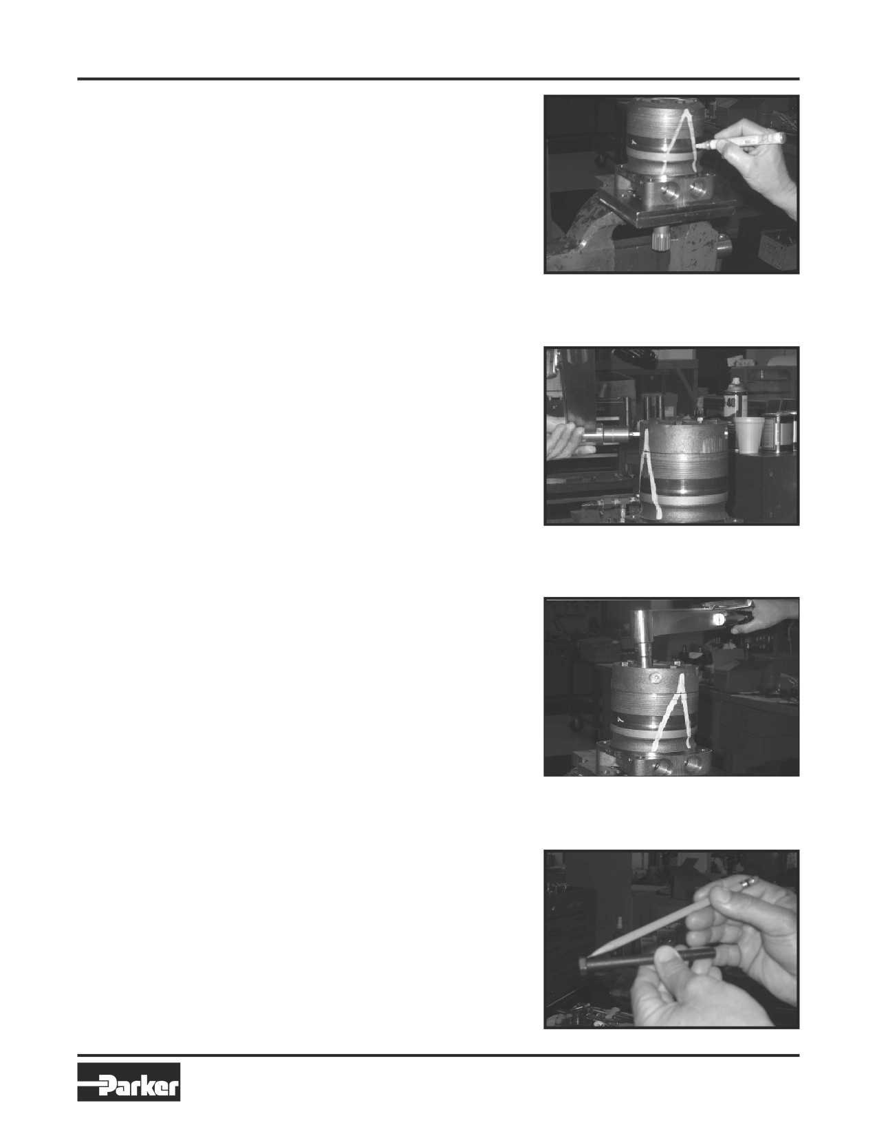
Place
1. Place the Torqmotor™ in a soft jawed vice,
Torqmotor
with coupling shaft (12) pointed down and
the vise jaws clamping firmly on the sides
in a vise
of the housing (18) mounting flange or port
bosses. Remove manifold port O-Rings
(18A) if applicable.
WARNING
WARNING: IF THE TORQMOTOR™ IS NOT
FIRMLY HELD IN THE VISE, IT COULD BE
Figure 3
DISLODGED DURING THE SERVICE PRO-
CEDURES, CAUSING INJURY.
Scribe alignment
2. Scribe an alignment mark down and across
mark & loose
the Torqmotor™ components from end
valve plugs
cover (2) to housing (18) to facilitate reas-
sembly orientation where required. Loosen
two shuttle or relief valve plugs (21) for
disassembly later if included in end cover.
3/16 or 3/8 inch Allen wrench or 1 inch hex
socket required. SEE FIGURES 3 & 4.
Figure 4
Figure 5
Remove special
3. Remove the five, six, or seven special
bolts &
ring head bolts (1, 1A, 1B, or 1C) using an
inspect bolts
appropriate 1/2 or 9/16 inch size socket.
SEE FIGURE 5. Inspect bolts for damaged
threads, or sealing rings, under the bolt
head. Replace damaged bolts. SEE FIGURE
6.
Figure 6
31
Parker Hannifin Corporation
Hydraulic Pump/Motor Division
Greeneville, TN 37745 US
HY13-1512-006-M1/USA
Torqmotor™ Service Procedure
Disassembly and Inspection
TC, TS, TB, TE, TJ, TF, TG, TH and TL Series
Remove end
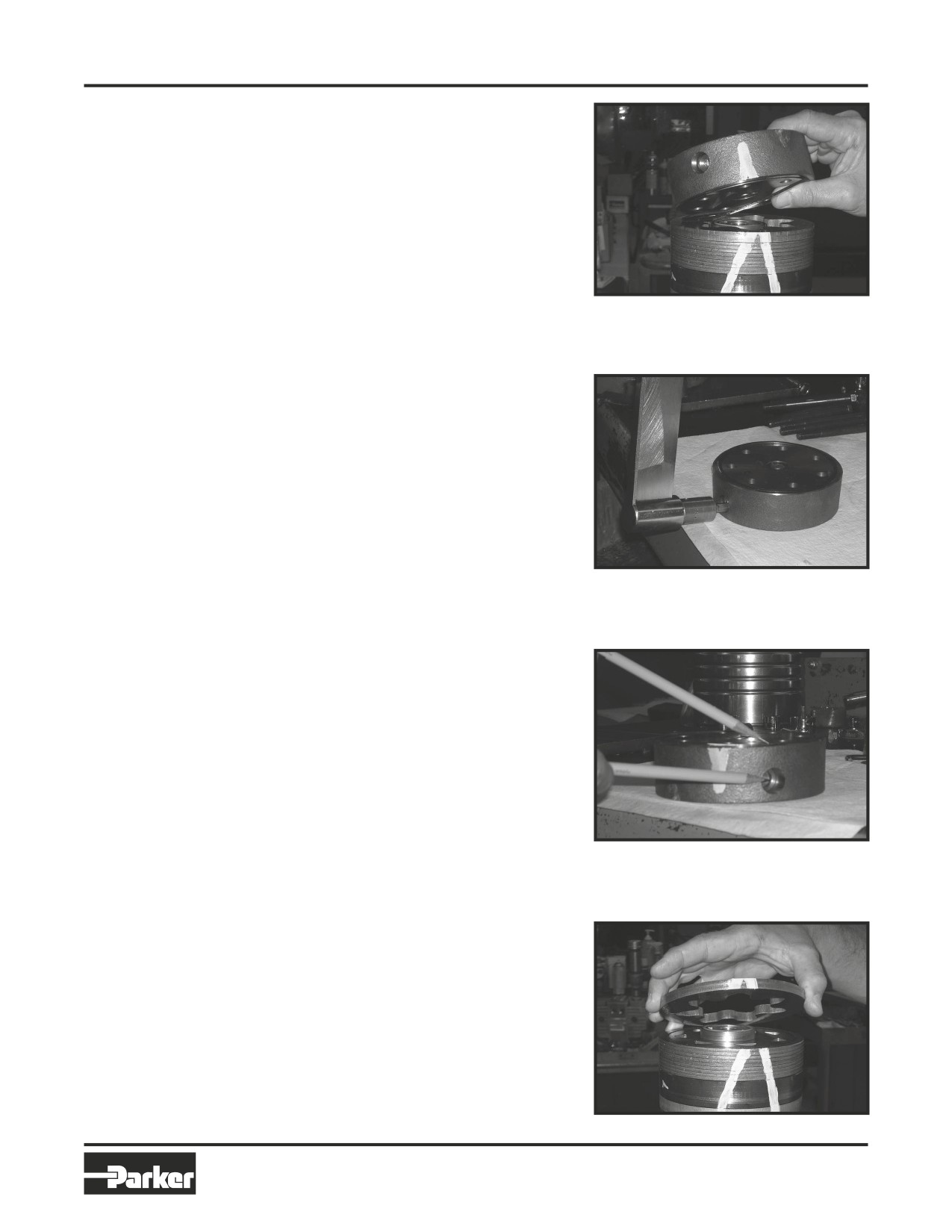
4. Remove end cover assembly (2) and seal
cover &
ring (4). Discard seal ring. SEE FIGURE 7.
inspect bolts
NOTE
NOTE: Refer to the appropriate “alternate
cover construction” on the exploded view
to determine the end cover construction
being serviced.
Figure 7
Remove plugs
5. If the end cover (2) is equipped with shuttle
and valves
valve or relief valve (24) components,
remove the two previously loosened plugs
(21) and o-rings (22). SEE FIGURE 8.
CAUTION
CAUTION: Be ready to catch the shuttle
valve or relief valve components that
will fall out of the end cover valve cavity
when the plugs are removed.
NOTE
NOTE: O-ring (22) is not included in seal
kits but serviced separately if required.
NOTE
NOTE: The insert and if included the
Figure 8
orifice plug in the end cover (2) must not
be removed as they are serviced as an
integral part of the end cover.
Wash & inspect
6. Thoroughly wash end cover (2) in proper
end cover
solvent and blow dry. Be sure the end cover
valve apertures, including the internal orifice
plug, are free of contamination. Inspect end
cover for cracks and the bolt head recesses
for good bolt head sealing surfaces. Re-
place end cover as necessary. SEE FIGURE
9.
Figure 9
NOTE
NOTE: A polished pattern (not scratches)
on the cover from rotation of the commu-
tator (5) is normal. Discoloration would
indicate excess fluid temperature, ther-
mal shock, or excess speed and require
system investigation for cause and close
inspection of end cover, commutator,
manifold, and rotor set.
Remove
7. Remove commutator ring (6). SEE FIGURE 10.
& inspect
Inspect commutator ring for cracks, or burrs.
commutator
ring
Figure 10
32
Parker Hannifin Corporation
Hydraulic Pump/Motor Division
Greeneville, TN 37745 US
HY13-1512-006-M1/USA
Torqmotor™ Service Procedure
Disassembly and Inspection
TC, TS, TB, TE, TJ, TF, TG, TH and TL Series
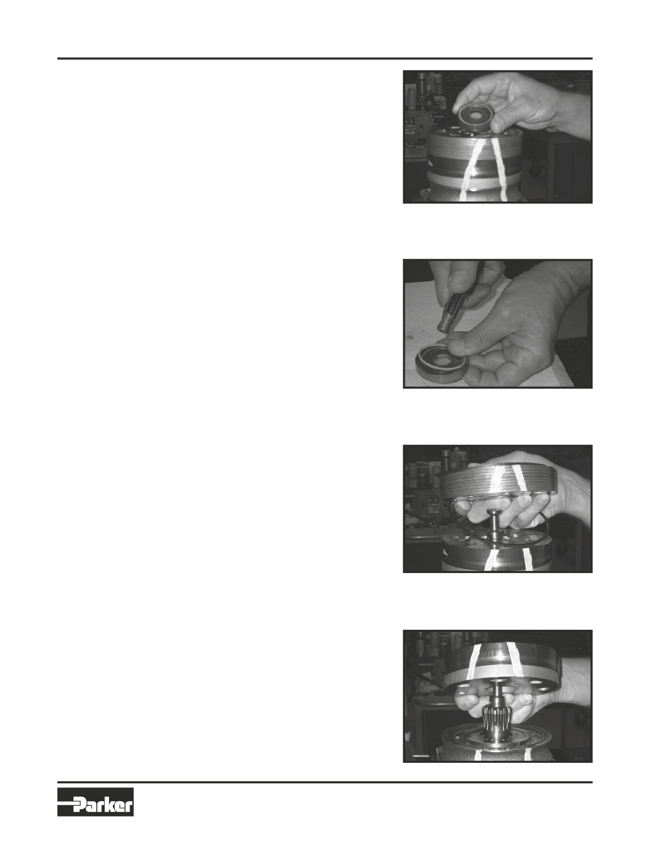
Remove &
8.
Remove commutator (5) and seal ring (3)
inspect
Remove seal ring from commutator, using
commutator
an air hose to blow air into ring groove until
seal ring is lifted out and discard seal ring.
Inspect commutator for cracks or burrs,
wear, scoring, spalling or brinelling. If any of
these conditions exist, replace commutator
and commutator ring as a matched set. SEE
FIGURE 11 & 12.
Remove mani-
9.
Remove manifold (7) and inspect for cracks
fold
surface scoring, brinelling or spalling.
Figure 11
Replace manifold if any of these conditions
exist. SEE FIGURE 13. A polished pattern
on the ground surface from commutator or
rotor rotation is normal. Remove and dis-
card the seal rings (4) that are on both sides
of the manifold.
NOTE
NOTE: The manifold is constructed of
plates bonded together to form an inte-
gral component not subject to further
disassembly for service. Compare con-
figuration of both sides of the manifold to
ensure that same surface is reassembled
against the rotor set.
Remove &
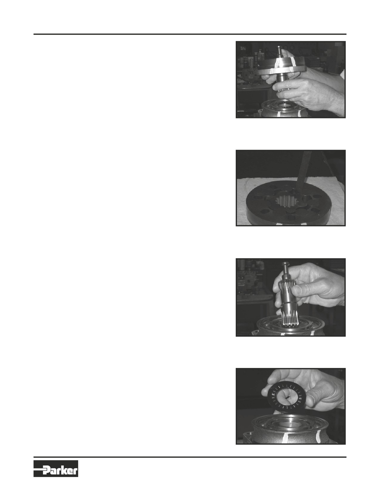
10. Remove rotor set (8) and wearplate (9),
Figure 12
inspect
together to retain the rotor set in its assem-
rotor set &
bled form, maintaining the same rotor vane
wearplate
(8C) to stator (8B) contact surfaces. SEE
FIGURE 14. The drive link (10) may come
away from the coupling shaft (12) with the
rotor set, and wearplate. You may have to
shift the rotor set on the wearplate to work
the drive link out of the rotor (8A) and wear-
plate. SEE FIGURE 15. Inspect the rotor
set in its assembled form for nicks, scoring,
or spalling on any surface and for broken
or worn splines. If the rotor set component
requires replacement, the complete rotor
set must be replaced as it is a matched set.
Inspect the wearplate for cracks, brinel-
Figure 13
ling, or scoring. Discard seal ring (4) that is
between the rotor set and wearplate.
NOTE
NOTE: The rotor set (8) components may
become disassembled during service pro-
cedures. Marking the surface of the rotor
and stator that is facing UP, with etching
ink or grease pencil before removal from
Torqmotor™ will ensure correct reassem-
bly of rotor into stator and rotor set into
Torqmotor™. Marking all rotor compo-
nents and mating spline components for
exact repositioning at assembly will en-
sure maximum wear life and performance
of rotor set and Torqmotor™.
Figure 14
33
Parker Hannifin Corporation
Hydraulic Pump/Motor Division
Greeneville, TN 37745 US
HY13-1512-006-M1/USA
Torqmotor™ Service Procedure
Disassembly and Inspection
TC, TS, TB, TE, TJ, TF, TG, TH and TL Series
NOTE
NOTE: Series TG or TH may have a rotor
set with two stator halves (8B & 8D) with
a seal ring (4) between them and two sets
of seven vanes (8C & 8E). Discard seal
ring only if stator halves become disas-
sembled during the service procedures.
NOTE
NOTE: A polished pattern on the wear
plate from rotor rotation is normal.
Figure 15
Check rotor,
11. Place rotor set (8) and wear plate (9) on a
vane clearance
flat surface and center rotor (8A) in stator
(8B) such that two rotor lobes (180 degrees
apart) and a roller vane (8C) centerline are
on the same stator centerline. Check the ro-
tor lobe to roller vane clearance with a feeler
gage at this common centerline. If there is
more than .005 inches (0.13 mm) of clear-
ance, replace rotor set. SEE FIGURE 16.
Figure 16
NOTE
NOTE: If rotor set (8) has two stator
halves (8B & 8D) and two sets of seven
vanes (8C & 8E) as shown in the alternate
construction TG rotor set assembly view,
check the rotor lobe to roller vane clear-
ance at both ends of rotor.
Remove & in-
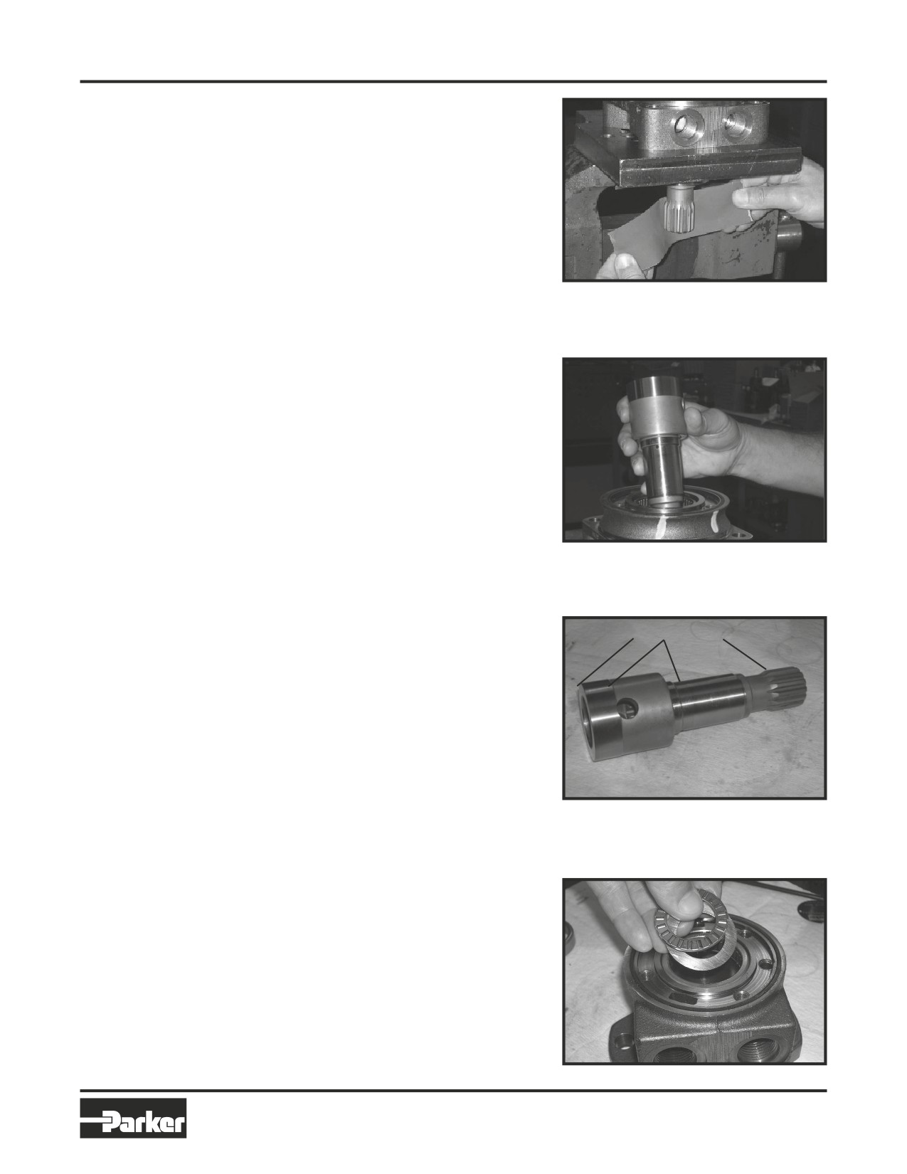
12. Remove drive link (10) from coupling shaft
spect
(12) if it was not removed with rotor set and
drive link
wear plate. Inspect drive link for cracks and
worn or damaged splines. No perceptible
lash (play) should be noted between mating
spline parts. SEE FIGURE 17. Remove and
Figure 17
discard seal ring (4) from housing (18).
Remove thrust
13. Remove thrust bearing (11) from top of
bearing
coupling shaft (12) if Torqmotor is a Series
TF, TG, TH or TL. Inspect for wear, brinel-
ling, corrosion and a full complement of
retained rollers. SEE FIGURE 18.
Figure 18
34
Parker Hannifin Corporation
Hydraulic Pump/Motor Division
Greeneville, TN 37745 US
HY13-1512-006-M1/USA
Torqmotor™ Service Procedure
Disassembly and Inspection
TC, TS, TB, TE, TJ, TF, TG, TH and TL Series
Check coupling
14. Check exposed portion of coupling shaft
shaft for rust
(12) to be sure you have removed all signs
or corrosion
of rust and corrosion which might prevent
its withdrawal through the seal and bear-
ing. Crocus cloth or fine emery paper may
be used. SEE FIGURE 19. Remove any key
(12A), nut (12B), washer (12C), bolt (12D),
lock washer (12E), or retaining ring (12F).
Figure 19
Remove &
15. Remove coupling shaft (12), by pushing on
inspect
the output end of shaft. SEE FIGURE 20.
coupling shaft
Inspect coupling shaft bearing and seal
surfaces for spalling, nicks, grooves, severe
wear or corrosion and discoloration. Inspect
for damaged or worn internal and external
splines or keyway. SEE FIGURE 21. Replace
coupling shaft if any of these conditions exist.
NOTE
NOTE: Minor shaft wear in seal area is
Figure 20
permissible. If wear exceeds .020 inches
(0.51 mm) diametrically, replace coupling
shaft.
Inspection Areas
NOTE
NOTE: A slight “polish” is permissible in
the shaft bearing areas. Anything more
would require coupling shaft replace-
ment.
Remove seal
16. Remove and discard seal ring (4) from hous-
ring from hous-
ing (18).
ing
Figure 21
Remove &
17. Remove thrust bearing (15) and thrust
inspect thrust
washer (14) if the unit is a Series TC, TS, TB
washer &
or TE. Inspect for wear, brinelling, corrosion
thrust bearing
and a full complement of retained rollers.
SEE FIGURE 22. Note: The TL motor has
only one thrust bearing and washer.
NOTE
NOTE: Large Frame Series TF, TG & TJ
Torqmotors have a thrust bearing (15)
sandwiched between two thrust washers
(14) that cannot be removed from hous-
ing (18) unless bearing (13) is removed for
Figure 22
replacement.
35
Parker Hannifin Corporation
Hydraulic Pump/Motor Division
Greeneville, TN 37745 US
HY13-1512-006-M1/USA
Torqmotor™ Service Procedure
Disassembly and Inspection
TC, TS, TB, TE, TJ, TF, TG, TH and TL Series
Remove seal
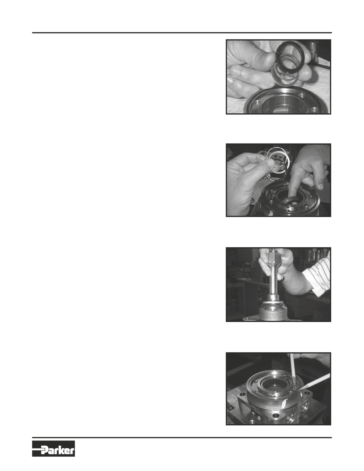
18. Remove seal (16) and back up ring (17) from
& washer or
Small Frame, TC, TB & TE housing (18) and
washers
backup washer (25). Discard both. SEE
FIGURE 23.
Remove seal (16), backup ring (17), and
backup washer (25) from Large Frame, Se-
ries TF, TG, TJ and TH housing by working
them around unseated thrust washers (14)
and thrust bearing (15) and out of the hous-
ing. Discard seal and washers. SEE FIGURE
Figure 23
24.
NOTE
NOTE: The original design units of Large
& Small Frame Torqmotors™ did not
include backup washer (25), but must
include backup washer (25) when reas-
sembled for service.
Figure 24
Remove seal
19. Remove housing (18) from vise, invert it and
remove and discard seal (20). A blind hole
bearing or seal puller is required.
SEE FIGURE 25.
Figure 25
Inspect
20. Inspect housing (18) assembly for cracks,
housing
the machined surfaces for nicks, burrs,
assembly
brinelling or corrosion. Remove burrs that
can be removed without changing dimen-
sional characteristics. Inspect tapped holes
for thread damage. SEE FIGURE 26. If the
housing is defective in these areas, discard
the housing assembly.
Figure 26
36
Parker Hannifin Corporation
Hydraulic Pump/Motor Division
Greeneville, TN 37745 US